EP3823498B1 - Stützvorrichtung für eine freitragende rohrförmige struktur - Google Patents
Stützvorrichtung für eine freitragende rohrförmige struktur Download PDFInfo
- Publication number
- EP3823498B1 EP3823498B1 EP19742955.8A EP19742955A EP3823498B1 EP 3823498 B1 EP3823498 B1 EP 3823498B1 EP 19742955 A EP19742955 A EP 19742955A EP 3823498 B1 EP3823498 B1 EP 3823498B1
- Authority
- EP
- European Patent Office
- Prior art keywords
- supporting
- hook portion
- supporting device
- tubular structure
- tubular element
- Prior art date
- Legal status (The legal status is an assumption and is not a legal conclusion. Google has not performed a legal analysis and makes no representation as to the accuracy of the status listed.)
- Active
Links
Images




Classifications
-
- A—HUMAN NECESSITIES
- A47—FURNITURE; DOMESTIC ARTICLES OR APPLIANCES; COFFEE MILLS; SPICE MILLS; SUCTION CLEANERS IN GENERAL
- A47B—TABLES; DESKS; OFFICE FURNITURE; CABINETS; DRAWERS; GENERAL DETAILS OF FURNITURE
- A47B95/00—Fittings for furniture
- A47B95/008—Suspension fittings for cabinets to be hung on walls
Definitions
- the present invention relates to a supporting device for a cantilevered tubular structure.
- Supporting devices called "hanging brackets" are used in the field of furnishing items or structures for furniture or parts thereof. In this way, the arrangement is determined of an element or structure which extends cantilevered from a wall at a certain height from the floor.
- Supporting device for a cantilevered structure is known from EP 0 363 868 A1 or EP 3 064 090 A1 .
- the general objective of the present invention is to overcome the above-mentioned drawbacks by providing a supporting device for a cantilevered tubular structure.
- a further objective of the invention is to provide a supporting device for a cantilevered tubular structure which is constructed so as not to protrude from the surface of the structure to which the device itself is fixed.
- the supporting device can be used completely, for example for containing objects or auxiliary items.
- a supporting device whose configuration is not protruding from the surface of the cantilevered tubular structure can be easily and economically hidden.
- Another objective of the invention is to provide a supporting device which, thanks to its assembly arrangement, is capable of supporting considerable loads.
- FIGS. 1-10 show a supporting device for a cantilevered tubular structure according to the invention suitable for fixing a cantilevered tubular structure 11 with respect to a wall 12, in various positions and arrangements.
- the cantilevered tubular structure 11 comprises a series of tubular elements, having various lengths, stably and firmly connected to each other in various ways, for creating shoulders, uprights, crossbars, supporting planes, etc. of a furnishing element, support or the like.
- the supporting device is arranged in correspondence with a tubular element 13, forming part of a series of tubular elements 13, 13', 13", etc., of the cantilevered tubular structure 11, for facing the panel 12, for example in the form of a wall or a wooden plank.
- the tubular structure 11 comprises at least one tubular element 13 facing the supporting wall 12. Said at least one tubular element 13 provides an opening 14 or window, which faces the supporting wall 12.
- the supporting device comprises in combination: a first hook portion 15 and a second supporting portion 16.
- the first hook portion 15 is fixed to the at least one tubular element 13 by introducing it according to the present invention into its interior from the above opening 14 or window.
- the second supporting portion 16 can be positioned and fixed to the supporting wall 12, for example by means of dowels 17 inserted in the supporting wall 12.
- the first hook portion 15 in the example is composed of a block 18 and adjustment mechanisms of the positions in depth (horizontal) and height (vertical) of said first hook portion 15 with respect to said second supporting portion 16, are associated therewith.
- a first adjustment mechanism of the vertical position or position in height provides an adjustment screw 19 which is screwed into a vertical threaded hole 20 passing into the block 18.
- a free end 21 of the adjustment screw 19 according to the present invention is engaged on an abutment plane or upper surface 22 formed in the second supporting portion 16.
- a second adjustment mechanism of the horizontal position or position in depth provides a second adjustment screw 23 which is screwed into a vertical threaded hole 24 also passing into the block 18.
- a free end 25 of the second adjustment screw 23 according to the present invention is engaged on a tilted abutment plane or tilted surface 26 formed in the second supporting portion 16.
- the tilted abutment plane or tilted surface 26 is formed in a tooth extension 27 which extends upwards from the upper surface 22 of the second supporting portion 16.
- the second supporting portion 16 in the example is also composed of a second block 28, in the example prismatic, the same as the first block 18, but not limited to this form. Like the second block 28, it provides an upper surface 22 from which the tooth extension 27 extends upwards bearing the tilted abutment plane or tilted surface 26.
- the tilted abutment plane or tilted surface 26 of the tooth extension 27 facing upwards is arranged in a direction complementary to that defined by a tooth extension 15' facing downwards of the first hook portion 15 of the block 18.
- first hook portion 15 of the block 18 provides the tooth extension 15' facing downwards which collaborates with the tooth extension 27 facing upwards of the second supporting portion 16.
- the figures show in examples, how the first hook portion 15, when positioned inside the at least one tubular element 13, is stably constrained in correspondence with the opening 14 to the same tubular element 13.
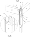
- first hook portion 15 when positioned inside the at least one tubular element 13, is stably constrained in correspondence with the opening 14 by means of a welding 29.
- Said welding 29 also helps to keep the block 18 of the first hook portion 15 in position also with the collaboration of a lowering or extension 30 formed outside the tooth extension 15'.
- Said lowering or extension 30 is in fact arranged in contact with an upper end 31 of the opening or window 14 of the tubular element 13.
- the lowering 30 can, in general, also be formed at the side of the block 18 of the first hook portion 15 to improve its stability and positioning inside the opening 14 and inside the tubular element 13.
- a second example of figures 5 and 5b shows how the first hook portion 15, when positioned inside the at least one tubular element 13, is stably constrained in correspondence with the opening by means of at least one plug 38.
- the plug 38 is inserted in a hole 32 of the tubular element 13 and then in an aligned hole (not shown) of the block 18.
- A The distance between a lower surface 33 of the block 28 of the second supporting portion 16 and a lower end 34 of the window 14 ( figure 9 ) is in fact indicated with A.
- B A possible relative movement between a lower free end 25 of the adjustment screw 23 and an upper free end of the tilted surface 26 of the second supporting portion 16 is also indicated with B (not shown in the drawings).
- Figure 1 shows the general arrangement that must be acquired between the tubular structure and elements of the supporting device of the invention before obtaining the correct positioning.
- the following figures illustrate the implementation steps.
- the first hook portion 15 formed ( figure 2 ) in the tubular element 13 is inserted, by introducing it into its interior from the above-mentioned opening 14 or window according to the present invention until the arrangement shown in figure 3 is reached.
- the first hook portion 15 is secured inside the tubular element 13.
- first hook portion 15 to be stably constrained in correspondence with the opening 14, for example by means of a welding 29 ( figures 4 and 4b ) or by means of a plug 38 ( figures 5 and 5b ).
- the supporting device must be completed in the operational position by engaging the second supporting portion 16 already previously fixed to the panel or wall 14.
- Figures 8 to 10 show how the first vertical adjustment or adjustment in height takes place. This is effected by acting with a tip 37 of a tool on the first adjustment screw 19 by rotating it according to the arrow H.
- the free end 21 of the adjustment screw 19 engages on the abutment plane 22 formed by the second supporting portion 16.
- the tubular structure 11 is therefore adjusted as shown by the arrow V of figure 10 .
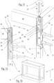
- Figures 11 to 13 show how the horizontal adjustment or adjustment in depth takes place.
- the tubular structure 11 is therefore adjusted as shown by the arrow O of figure 13 .
- tubular structure is shown with tubular elements having a rectangular section, but it is clear that the section can alternatively have other forms such as triangular, rectangular, circular, etc.
- the blocks 18 and 28 of the first hook portion 15 and of the second supporting portion 16 of the supporting device preferably, also have a section complementary to that of the tubular elements of the tubular structure.
- first hook portion 15 is inserted in correspondence with a tubular element acting as an upright, but it could also be inserted in a tubular element having the function of a crossbar.
- the tubular structure 11 can be a framework for a wall cupboard or a structure capable of receiving various kinds of planes or closing walls, etc.
Landscapes
- Standing Axle, Rod, Or Tube Structures Coupled By Welding, Adhesion, Or Deposition (AREA)
- Connection Of Plates (AREA)
- Supports For Pipes And Cables (AREA)
- Supplying Of Containers To The Packaging Station (AREA)
- Centrifugal Separators (AREA)
Claims (11)
- Stützvorrichtung für einen freitragenden rohrförmigen Aufbau (11), der einen rohrförmigen Aufbau (11) umfasst, der wiederum mindestens ein rohrförmiges Element (13) umfasst, das einer Stützwand (12) zugewandt ist, wobei das mindestens eine rohrförmige Element (13) eine Öffnung (14) bereitstellt, die der Stützwand (12) zugewandt ist, wobei die Vorrichtung in Kombination umfasst: einen ersten Hakenabschnitt (15), der an dem mindestens einen rohrförmigen Element (13) befestigt ist, und einen zweiten positionierbaren Stützabschnitt (16), der an der Stützwand (12) befestigbar ist, wobei dem ersten Hakenabschnitt (15) Einstellmechanismen für die Positionen in der Tiefe und der Höhe des ersten Hakenabschnitts (15) in Bezug auf den zweiten Stützabschnitt (16) zugeordnet sind, dadurch gekennzeichnet, dass der erste Hakenabschnitt (15) im Inneren des mindestens einen rohrförmigen Elements (13) angeordnet ist und in Übereinstimmung mit der Öffnung (14) eingespannt ist.
- Stützvorrichtung nach Anspruch 1, dadurch gekennzeichnet, dass der erste Hakenabschnitt (15) eine Zahnverlängerung (15') aufweist, die nach unten weist, und dass der zweite Stützabschnitt (16) eine Zahnverlängerung (27) bereitstellt, die nach oben weist, wobei die Zahnverlängerung (15') des ersten Hakenabschnitts (15) und die Zahnverlängerung (27) des zweiten Stützabschnitts (16) geneigte Ebenen aufweisen, die in einer komplementären Richtung zueinander angeordnet sind.
- Stützvorrichtung nach einem der Ansprüche 1 oder 2, dadurch gekennzeichnet, dass der erste Hakenabschnitt (15) und der zweite Stützabschnitt (16) aus Blöcken (18, 28) zusammengesetzt sind.
- Stützvorrichtung nach einem der vorhergehenden Ansprüche, dadurch gekennzeichnet, dass die Einstellmechanismen, die dem ersten Hakenabschnitt (15) zugeordnet sind, zwei Einstellschrauben (19, 23) sind, die innerhalb von Durchgangsgewindelöchern (20, 24) eines Blocks (18) des ersten Hakenabschnitts (15) angeordnet sind.
- Stützvorrichtung nach Anspruch 4, dadurch gekennzeichnet, dass ein freies Ende (21) einer ersten Schraube (19) der beiden Einstellschrauben mit einer auf dem zweiten Stützabschnitt (16) ausgebildeten Anschlagebene (22) in Eingriff steht.
- Stützvorrichtung nach Anspruch 4, dadurch gekennzeichnet, dass ein freies Ende (25) einer zweiten Schraube (23) der beiden Einstellschrauben mit einer geneigten Anschlagebene (26) in Eingriff steht, die in der Zahnverlängerung (27) ausgebildet ist und von dem zweiten Stützabschnitt (16) nach oben weist.
- Stützvorrichtung nach einem der vorhergehenden Ansprüche, dadurch gekennzeichnet, dass der erste Hakenabschnitt (15) eine Verlängerung (30) aufweist, die in Kontakt mit der Öffnung (14) des rohrförmigen Elements (13) positioniert ist.
- Stützvorrichtung nach einem der vorhergehenden Ansprüche, dadurch gekennzeichnet, dass der zweite Stützabschnitt (16) an der Stützwand (12) mittels Dübeln (17) befestigt ist, die in die Stützwand (12) eingesetzt sind.
- Stützvorrichtung nach einem der vorhergehenden Ansprüche, dadurch gekennzeichnet, dass der rohrförmige Aufbau (11) einen rechteckigen oder quadratischen Querschnitt aufweist.
- Stützvorrichtung nach einem der Ansprüche 1 bis 9, dadurch gekennzeichnet, dass der erste Hakenabschnitt (15) an dem mindestens einen rohrförmigen Element (13) durch Schweißen (29) befestigt ist.
- Stützvorrichtung nach einem der Ansprüche 1 bis 9, dadurch gekennzeichnet, dass der erste Hakenabschnitt (15) an dem mindestens einen rohrförmigen Element (13) mit Hilfe mindestens eines Stopfens (38) befestigt ist.
Applications Claiming Priority (2)
| Application Number | Priority Date | Filing Date | Title |
|---|---|---|---|
| IT102018000007330A IT201800007330A1 (it) | 2018-07-19 | 2018-07-19 | Dispositivo di supporto per una struttura tubolare a sbalzo |
| PCT/IB2019/055783 WO2020016698A1 (en) | 2018-07-19 | 2019-07-08 | Supporting device for a cantilevered tubular structure |
Publications (2)
| Publication Number | Publication Date |
|---|---|
| EP3823498A1 EP3823498A1 (de) | 2021-05-26 |
| EP3823498B1 true EP3823498B1 (de) | 2023-08-30 |
Family
ID=63834523
Family Applications (1)
| Application Number | Title | Priority Date | Filing Date |
|---|---|---|---|
| EP19742955.8A Active EP3823498B1 (de) | 2018-07-19 | 2019-07-08 | Stützvorrichtung für eine freitragende rohrförmige struktur |
Country Status (4)
| Country | Link |
|---|---|
| EP (1) | EP3823498B1 (de) |
| ES (1) | ES2963431T3 (de) |
| IT (1) | IT201800007330A1 (de) |
| WO (1) | WO2020016698A1 (de) |
Families Citing this family (2)
| Publication number | Priority date | Publication date | Assignee | Title |
|---|---|---|---|---|
| KR200499681Y1 (ko) * | 2021-10-29 | 2025-10-17 | (주)엘엑스하우시스 | 벽걸이 수납 가구 |
| CN116145826B (zh) * | 2023-01-06 | 2025-04-18 | 浙江省二建建设集团有限公司 | 建筑结构连接装置及其使用方法 |
Family Cites Families (2)
| Publication number | Priority date | Publication date | Assignee | Title |
|---|---|---|---|---|
| FR2637789B1 (fr) * | 1988-10-14 | 1992-01-10 | Bonnet Sa | Meuble de cuisson |
| EP3064090B1 (de) * | 2015-03-05 | 2017-12-27 | Leonardo S.r.L. | Verbesserungen an einer verborgenen vorrichtung zur wandmontage eines möbelstücks und strukturbauteil eines möbelstücks mit dieser vorrichtung |
-
2018
- 2018-07-19 IT IT102018000007330A patent/IT201800007330A1/it unknown
-
2019
- 2019-07-08 ES ES19742955T patent/ES2963431T3/es active Active
- 2019-07-08 EP EP19742955.8A patent/EP3823498B1/de active Active
- 2019-07-08 WO PCT/IB2019/055783 patent/WO2020016698A1/en not_active Ceased
Also Published As
| Publication number | Publication date |
|---|---|
| IT201800007330A1 (it) | 2020-01-19 |
| EP3823498A1 (de) | 2021-05-26 |
| ES2963431T3 (es) | 2024-03-27 |
| WO2020016698A1 (en) | 2020-01-23 |
Similar Documents
| Publication | Publication Date | Title |
|---|---|---|
| US8297576B2 (en) | Fixture mounting bracket assembly | |
| EP2238871B1 (de) | System für die Herstellung einer an einer Wand, insbesondere Raumwand, montierbaren Multifunktionswand und Verfahren zur Herstellung und Montage einer Multifunktionswand | |
| US10722030B2 (en) | Blade based cabinet system | |
| EP3682125B1 (de) | Einheitliches verbindungs- und ausgleichssystem für teile von möbeln und einrichtungsgegenständen | |
| EP2890853A1 (de) | Von vorne einstellbare montagevorrichtung für eine wandtafel | |
| EP3823498B1 (de) | Stützvorrichtung für eine freitragende rohrförmige struktur | |
| US12193571B2 (en) | Floating fixture wall mount system and method of use | |
| EP3005904B1 (de) | Tragstruktur mit tragprofil und trägerarmen | |
| EP3676465B1 (de) | System zur montage von wandverkleidungstafeln | |
| EP3678512A1 (de) | Verbindungs- und nivelliersystem für möbelteile und möbelartikel mit der schulter auf dem boden | |
| KR20180007461A (ko) | 마감패널 조립구조 | |
| EP2510834A1 (de) | Versteckte Vorrichtung für die Wandanordnung einer strukturellen Komponente eins Möbelstücks mit Seitenregulierung | |
| EP3328245B1 (de) | Verankerungsgruppe für wandschränke mit erhöhter kapazität mit regulierung von unten | |
| EP3328244B1 (de) | Verankerungsgruppe für wandschränke mit regulierung von unten | |
| EP3328246B1 (de) | Verankerungsgruppe für wandschränke mit erhöhter leistungsfähigkeit mit regelung von oben | |
| EP3897293B1 (de) | Schublade mit aushebesicherung | |
| KR200294493Y1 (ko) | 선반 설치대 | |
| US20090008523A1 (en) | Support Bracket for Shelves | |
| WO2024231833A1 (en) | Furniture structure for the support and/or containment of objects | |
| ITPD20070008A1 (it) | Dispositivo regolabile di aggancio a muro per librerie e scaffali in genere | |
| EP0793927A1 (de) | Drehführung und damit ausgestattetes System und Lager | |
| GB2475712A (en) | Hinged access door allowing offset opening | |
| AU2017201881A1 (en) | A Support Assembly for Supporting Structural Components | |
| NZ545124A (en) | Modular panelling system |
Legal Events
| Date | Code | Title | Description |
|---|---|---|---|
| STAA | Information on the status of an ep patent application or granted ep patent |
Free format text: STATUS: UNKNOWN |
|
| STAA | Information on the status of an ep patent application or granted ep patent |
Free format text: STATUS: THE INTERNATIONAL PUBLICATION HAS BEEN MADE |
|
| PUAI | Public reference made under article 153(3) epc to a published international application that has entered the european phase |
Free format text: ORIGINAL CODE: 0009012 |
|
| STAA | Information on the status of an ep patent application or granted ep patent |
Free format text: STATUS: REQUEST FOR EXAMINATION WAS MADE |
|
| 17P | Request for examination filed |
Effective date: 20201203 |
|
| AK | Designated contracting states |
Kind code of ref document: A1 Designated state(s): AL AT BE BG CH CY CZ DE DK EE ES FI FR GB GR HR HU IE IS IT LI LT LU LV MC MK MT NL NO PL PT RO RS SE SI SK SM TR |
|
| DAV | Request for validation of the european patent (deleted) | ||
| DAX | Request for extension of the european patent (deleted) | ||
| GRAP | Despatch of communication of intention to grant a patent |
Free format text: ORIGINAL CODE: EPIDOSNIGR1 |
|
| STAA | Information on the status of an ep patent application or granted ep patent |
Free format text: STATUS: GRANT OF PATENT IS INTENDED |
|
| INTG | Intention to grant announced |
Effective date: 20230426 |
|
| GRAS | Grant fee paid |
Free format text: ORIGINAL CODE: EPIDOSNIGR3 |
|
| GRAA | (expected) grant |
Free format text: ORIGINAL CODE: 0009210 |
|
| STAA | Information on the status of an ep patent application or granted ep patent |
Free format text: STATUS: THE PATENT HAS BEEN GRANTED |
|
| AK | Designated contracting states |
Kind code of ref document: B1 Designated state(s): AL AT BE BG CH CY CZ DE DK EE ES FI FR GB GR HR HU IE IS IT LI LT LU LV MC MK MT NL NO PL PT RO RS SE SI SK SM TR |
|
| REG | Reference to a national code |
Ref country code: GB Ref legal event code: FG4D |
|
| REG | Reference to a national code |
Ref country code: CH Ref legal event code: EP |
|
| P01 | Opt-out of the competence of the unified patent court (upc) registered |
Effective date: 20230728 |
|
| REG | Reference to a national code |
Ref country code: DE Ref legal event code: R096 Ref document number: 602019036168 Country of ref document: DE |
|
| REG | Reference to a national code |
Ref country code: IE Ref legal event code: FG4D |
|
| REG | Reference to a national code |
Ref country code: LT Ref legal event code: MG9D |
|
| REG | Reference to a national code |
Ref country code: NL Ref legal event code: MP Effective date: 20230830 |
|
| REG | Reference to a national code |
Ref country code: AT Ref legal event code: MK05 Ref document number: 1604251 Country of ref document: AT Kind code of ref document: T Effective date: 20230830 |
|
| PG25 | Lapsed in a contracting state [announced via postgrant information from national office to epo] |
Ref country code: GR Free format text: LAPSE BECAUSE OF FAILURE TO SUBMIT A TRANSLATION OF THE DESCRIPTION OR TO PAY THE FEE WITHIN THE PRESCRIBED TIME-LIMIT Effective date: 20231201 |
|
| PG25 | Lapsed in a contracting state [announced via postgrant information from national office to epo] |
Ref country code: IS Free format text: LAPSE BECAUSE OF FAILURE TO SUBMIT A TRANSLATION OF THE DESCRIPTION OR TO PAY THE FEE WITHIN THE PRESCRIBED TIME-LIMIT Effective date: 20231230 |
|
| PG25 | Lapsed in a contracting state [announced via postgrant information from national office to epo] |
Ref country code: SE Free format text: LAPSE BECAUSE OF FAILURE TO SUBMIT A TRANSLATION OF THE DESCRIPTION OR TO PAY THE FEE WITHIN THE PRESCRIBED TIME-LIMIT Effective date: 20230830 Ref country code: RS Free format text: LAPSE BECAUSE OF FAILURE TO SUBMIT A TRANSLATION OF THE DESCRIPTION OR TO PAY THE FEE WITHIN THE PRESCRIBED TIME-LIMIT Effective date: 20230830 Ref country code: NO Free format text: LAPSE BECAUSE OF FAILURE TO SUBMIT A TRANSLATION OF THE DESCRIPTION OR TO PAY THE FEE WITHIN THE PRESCRIBED TIME-LIMIT Effective date: 20231130 Ref country code: LV Free format text: LAPSE BECAUSE OF FAILURE TO SUBMIT A TRANSLATION OF THE DESCRIPTION OR TO PAY THE FEE WITHIN THE PRESCRIBED TIME-LIMIT Effective date: 20230830 Ref country code: LT Free format text: LAPSE BECAUSE OF FAILURE TO SUBMIT A TRANSLATION OF THE DESCRIPTION OR TO PAY THE FEE WITHIN THE PRESCRIBED TIME-LIMIT Effective date: 20230830 Ref country code: IS Free format text: LAPSE BECAUSE OF FAILURE TO SUBMIT A TRANSLATION OF THE DESCRIPTION OR TO PAY THE FEE WITHIN THE PRESCRIBED TIME-LIMIT Effective date: 20231230 Ref country code: HR Free format text: LAPSE BECAUSE OF FAILURE TO SUBMIT A TRANSLATION OF THE DESCRIPTION OR TO PAY THE FEE WITHIN THE PRESCRIBED TIME-LIMIT Effective date: 20230830 Ref country code: GR Free format text: LAPSE BECAUSE OF FAILURE TO SUBMIT A TRANSLATION OF THE DESCRIPTION OR TO PAY THE FEE WITHIN THE PRESCRIBED TIME-LIMIT Effective date: 20231201 Ref country code: FI Free format text: LAPSE BECAUSE OF FAILURE TO SUBMIT A TRANSLATION OF THE DESCRIPTION OR TO PAY THE FEE WITHIN THE PRESCRIBED TIME-LIMIT Effective date: 20230830 Ref country code: AT Free format text: LAPSE BECAUSE OF FAILURE TO SUBMIT A TRANSLATION OF THE DESCRIPTION OR TO PAY THE FEE WITHIN THE PRESCRIBED TIME-LIMIT Effective date: 20230830 |
|
| PG25 | Lapsed in a contracting state [announced via postgrant information from national office to epo] |
Ref country code: PL Free format text: LAPSE BECAUSE OF FAILURE TO SUBMIT A TRANSLATION OF THE DESCRIPTION OR TO PAY THE FEE WITHIN THE PRESCRIBED TIME-LIMIT Effective date: 20230830 Ref country code: NL Free format text: LAPSE BECAUSE OF FAILURE TO SUBMIT A TRANSLATION OF THE DESCRIPTION OR TO PAY THE FEE WITHIN THE PRESCRIBED TIME-LIMIT Effective date: 20230830 |
|
| REG | Reference to a national code |
Ref country code: ES Ref legal event code: FG2A Ref document number: 2963431 Country of ref document: ES Kind code of ref document: T3 Effective date: 20240327 |
|
| PG25 | Lapsed in a contracting state [announced via postgrant information from national office to epo] |
Ref country code: SM Free format text: LAPSE BECAUSE OF FAILURE TO SUBMIT A TRANSLATION OF THE DESCRIPTION OR TO PAY THE FEE WITHIN THE PRESCRIBED TIME-LIMIT Effective date: 20230830 Ref country code: RO Free format text: LAPSE BECAUSE OF FAILURE TO SUBMIT A TRANSLATION OF THE DESCRIPTION OR TO PAY THE FEE WITHIN THE PRESCRIBED TIME-LIMIT Effective date: 20230830 Ref country code: EE Free format text: LAPSE BECAUSE OF FAILURE TO SUBMIT A TRANSLATION OF THE DESCRIPTION OR TO PAY THE FEE WITHIN THE PRESCRIBED TIME-LIMIT Effective date: 20230830 Ref country code: DK Free format text: LAPSE BECAUSE OF FAILURE TO SUBMIT A TRANSLATION OF THE DESCRIPTION OR TO PAY THE FEE WITHIN THE PRESCRIBED TIME-LIMIT Effective date: 20230830 Ref country code: CZ Free format text: LAPSE BECAUSE OF FAILURE TO SUBMIT A TRANSLATION OF THE DESCRIPTION OR TO PAY THE FEE WITHIN THE PRESCRIBED TIME-LIMIT Effective date: 20230830 Ref country code: SK Free format text: LAPSE BECAUSE OF FAILURE TO SUBMIT A TRANSLATION OF THE DESCRIPTION OR TO PAY THE FEE WITHIN THE PRESCRIBED TIME-LIMIT Effective date: 20230830 Ref country code: PT Free format text: LAPSE BECAUSE OF FAILURE TO SUBMIT A TRANSLATION OF THE DESCRIPTION OR TO PAY THE FEE WITHIN THE PRESCRIBED TIME-LIMIT Effective date: 20240102 |
|
| REG | Reference to a national code |
Ref country code: DE Ref legal event code: R097 Ref document number: 602019036168 Country of ref document: DE |
|
| PLBE | No opposition filed within time limit |
Free format text: ORIGINAL CODE: 0009261 |
|
| STAA | Information on the status of an ep patent application or granted ep patent |
Free format text: STATUS: NO OPPOSITION FILED WITHIN TIME LIMIT |
|
| PG25 | Lapsed in a contracting state [announced via postgrant information from national office to epo] |
Ref country code: SI Free format text: LAPSE BECAUSE OF FAILURE TO SUBMIT A TRANSLATION OF THE DESCRIPTION OR TO PAY THE FEE WITHIN THE PRESCRIBED TIME-LIMIT Effective date: 20230830 |
|
| 26N | No opposition filed |
Effective date: 20240603 |
|
| PG25 | Lapsed in a contracting state [announced via postgrant information from national office to epo] |
Ref country code: BG Free format text: LAPSE BECAUSE OF FAILURE TO SUBMIT A TRANSLATION OF THE DESCRIPTION OR TO PAY THE FEE WITHIN THE PRESCRIBED TIME-LIMIT Effective date: 20230830 |
|
| PG25 | Lapsed in a contracting state [announced via postgrant information from national office to epo] |
Ref country code: BG Free format text: LAPSE BECAUSE OF FAILURE TO SUBMIT A TRANSLATION OF THE DESCRIPTION OR TO PAY THE FEE WITHIN THE PRESCRIBED TIME-LIMIT Effective date: 20230830 |
|
| PG25 | Lapsed in a contracting state [announced via postgrant information from national office to epo] |
Ref country code: MC Free format text: LAPSE BECAUSE OF FAILURE TO SUBMIT A TRANSLATION OF THE DESCRIPTION OR TO PAY THE FEE WITHIN THE PRESCRIBED TIME-LIMIT Effective date: 20230830 |
|
| REG | Reference to a national code |
Ref country code: CH Ref legal event code: PL |
|
| PG25 | Lapsed in a contracting state [announced via postgrant information from national office to epo] |
Ref country code: LU Free format text: LAPSE BECAUSE OF NON-PAYMENT OF DUE FEES Effective date: 20240708 |
|
| GBPC | Gb: european patent ceased through non-payment of renewal fee |
Effective date: 20240708 |
|
| PG25 | Lapsed in a contracting state [announced via postgrant information from national office to epo] |
Ref country code: LU Free format text: LAPSE BECAUSE OF NON-PAYMENT OF DUE FEES Effective date: 20240708 |
|
| PG25 | Lapsed in a contracting state [announced via postgrant information from national office to epo] |
Ref country code: CH Free format text: LAPSE BECAUSE OF NON-PAYMENT OF DUE FEES Effective date: 20240731 Ref country code: BE Free format text: LAPSE BECAUSE OF NON-PAYMENT OF DUE FEES Effective date: 20240731 |
|
| PG25 | Lapsed in a contracting state [announced via postgrant information from national office to epo] |
Ref country code: GB Free format text: LAPSE BECAUSE OF NON-PAYMENT OF DUE FEES Effective date: 20240708 |
|
| REG | Reference to a national code |
Ref country code: BE Ref legal event code: MM Effective date: 20240731 |
|
| PG25 | Lapsed in a contracting state [announced via postgrant information from national office to epo] |
Ref country code: IE Free format text: LAPSE BECAUSE OF NON-PAYMENT OF DUE FEES Effective date: 20240708 |
|
| PGFP | Annual fee paid to national office [announced via postgrant information from national office to epo] |
Ref country code: ES Payment date: 20250801 Year of fee payment: 7 |
|
| PGFP | Annual fee paid to national office [announced via postgrant information from national office to epo] |
Ref country code: DE Payment date: 20250729 Year of fee payment: 7 |
|
| PGFP | Annual fee paid to national office [announced via postgrant information from national office to epo] |
Ref country code: IT Payment date: 20250716 Year of fee payment: 7 |
|
| PGFP | Annual fee paid to national office [announced via postgrant information from national office to epo] |
Ref country code: FR Payment date: 20250725 Year of fee payment: 7 |
|
| PG25 | Lapsed in a contracting state [announced via postgrant information from national office to epo] |
Ref country code: CY Free format text: LAPSE BECAUSE OF FAILURE TO SUBMIT A TRANSLATION OF THE DESCRIPTION OR TO PAY THE FEE WITHIN THE PRESCRIBED TIME-LIMIT; INVALID AB INITIO Effective date: 20190708 |
|
| PG25 | Lapsed in a contracting state [announced via postgrant information from national office to epo] |
Ref country code: HU Free format text: LAPSE BECAUSE OF FAILURE TO SUBMIT A TRANSLATION OF THE DESCRIPTION OR TO PAY THE FEE WITHIN THE PRESCRIBED TIME-LIMIT; INVALID AB INITIO Effective date: 20190708 |