EP3824165B1 - Variable ventiltriebvorrichtung - Google Patents
Variable ventiltriebvorrichtung Download PDFInfo
- Publication number
- EP3824165B1 EP3824165B1 EP19745032.3A EP19745032A EP3824165B1 EP 3824165 B1 EP3824165 B1 EP 3824165B1 EP 19745032 A EP19745032 A EP 19745032A EP 3824165 B1 EP3824165 B1 EP 3824165B1
- Authority
- EP
- European Patent Office
- Prior art keywords
- camshaft
- cam element
- drive device
- valve drive
- ramp surface
- Prior art date
- Legal status (The legal status is an assumption and is not a legal conclusion. Google has not performed a legal analysis and makes no representation as to the accuracy of the status listed.)
- Active
Links
Images

Classifications
-
- F—MECHANICAL ENGINEERING; LIGHTING; HEATING; WEAPONS; BLASTING
- F01—MACHINES OR ENGINES IN GENERAL; ENGINE PLANTS IN GENERAL; STEAM ENGINES
- F01L—CYCLICALLY OPERATING VALVES FOR MACHINES OR ENGINES
- F01L1/00—Valve-gear or valve arrangements, e.g. lift-valve gear
- F01L1/02—Valve drive
- F01L1/04—Valve drive by means of cams, camshafts, cam discs, eccentrics or the like
- F01L1/047—Camshafts
-
- F—MECHANICAL ENGINEERING; LIGHTING; HEATING; WEAPONS; BLASTING
- F01—MACHINES OR ENGINES IN GENERAL; ENGINE PLANTS IN GENERAL; STEAM ENGINES
- F01L—CYCLICALLY OPERATING VALVES FOR MACHINES OR ENGINES
- F01L1/00—Valve-gear or valve arrangements, e.g. lift-valve gear
- F01L1/02—Valve drive
- F01L1/04—Valve drive by means of cams, camshafts, cam discs, eccentrics or the like
- F01L1/047—Camshafts
- F01L1/053—Camshafts overhead type
-
- F—MECHANICAL ENGINEERING; LIGHTING; HEATING; WEAPONS; BLASTING
- F01—MACHINES OR ENGINES IN GENERAL; ENGINE PLANTS IN GENERAL; STEAM ENGINES
- F01L—CYCLICALLY OPERATING VALVES FOR MACHINES OR ENGINES
- F01L1/00—Valve-gear or valve arrangements, e.g. lift-valve gear
- F01L1/02—Valve drive
- F01L1/04—Valve drive by means of cams, camshafts, cam discs, eccentrics or the like
- F01L1/08—Shape of cams
-
- F—MECHANICAL ENGINEERING; LIGHTING; HEATING; WEAPONS; BLASTING
- F01—MACHINES OR ENGINES IN GENERAL; ENGINE PLANTS IN GENERAL; STEAM ENGINES
- F01L—CYCLICALLY OPERATING VALVES FOR MACHINES OR ENGINES
- F01L13/00—Modifications of valve-gear to facilitate reversing, braking, starting, changing compression ratio, or other specific operations
-
- F—MECHANICAL ENGINEERING; LIGHTING; HEATING; WEAPONS; BLASTING
- F01—MACHINES OR ENGINES IN GENERAL; ENGINE PLANTS IN GENERAL; STEAM ENGINES
- F01L—CYCLICALLY OPERATING VALVES FOR MACHINES OR ENGINES
- F01L13/00—Modifications of valve-gear to facilitate reversing, braking, starting, changing compression ratio, or other specific operations
- F01L13/0015—Modifications of valve-gear to facilitate reversing, braking, starting, changing compression ratio, or other specific operations for optimising engine performances by modifying valve lift according to various working parameters, e.g. rotational speed, load, torque
- F01L13/0036—Modifications of valve-gear to facilitate reversing, braking, starting, changing compression ratio, or other specific operations for optimising engine performances by modifying valve lift according to various working parameters, e.g. rotational speed, load, torque the valves being driven by two or more cams with different shape, size or timing or a single cam profiled in axial and radial direction
-
- F—MECHANICAL ENGINEERING; LIGHTING; HEATING; WEAPONS; BLASTING
- F01—MACHINES OR ENGINES IN GENERAL; ENGINE PLANTS IN GENERAL; STEAM ENGINES
- F01L—CYCLICALLY OPERATING VALVES FOR MACHINES OR ENGINES
- F01L13/00—Modifications of valve-gear to facilitate reversing, braking, starting, changing compression ratio, or other specific operations
- F01L13/0015—Modifications of valve-gear to facilitate reversing, braking, starting, changing compression ratio, or other specific operations for optimising engine performances by modifying valve lift according to various working parameters, e.g. rotational speed, load, torque
- F01L13/0057—Modifications of valve-gear to facilitate reversing, braking, starting, changing compression ratio, or other specific operations for optimising engine performances by modifying valve lift according to various working parameters, e.g. rotational speed, load, torque by splittable or deformable cams
-
- F—MECHANICAL ENGINEERING; LIGHTING; HEATING; WEAPONS; BLASTING
- F01—MACHINES OR ENGINES IN GENERAL; ENGINE PLANTS IN GENERAL; STEAM ENGINES
- F01L—CYCLICALLY OPERATING VALVES FOR MACHINES OR ENGINES
- F01L1/00—Valve-gear or valve arrangements, e.g. lift-valve gear
- F01L1/12—Transmitting gear between valve drive and valve
- F01L1/18—Rocking arms or levers
- F01L1/181—Centre pivot rocking arms
-
- F—MECHANICAL ENGINEERING; LIGHTING; HEATING; WEAPONS; BLASTING
- F01—MACHINES OR ENGINES IN GENERAL; ENGINE PLANTS IN GENERAL; STEAM ENGINES
- F01L—CYCLICALLY OPERATING VALVES FOR MACHINES OR ENGINES
- F01L1/00—Valve-gear or valve arrangements, e.g. lift-valve gear
- F01L1/02—Valve drive
- F01L1/04—Valve drive by means of cams, camshafts, cam discs, eccentrics or the like
- F01L1/047—Camshafts
- F01L2001/0471—Assembled camshafts
- F01L2001/0473—Composite camshafts, e.g. with cams or cam sleeve being able to move relative to the inner camshaft or a cam adjusting rod
-
- F—MECHANICAL ENGINEERING; LIGHTING; HEATING; WEAPONS; BLASTING
- F01—MACHINES OR ENGINES IN GENERAL; ENGINE PLANTS IN GENERAL; STEAM ENGINES
- F01L—CYCLICALLY OPERATING VALVES FOR MACHINES OR ENGINES
- F01L2250/00—Camshaft drives characterised by their transmission means
- F01L2250/02—Camshaft drives characterised by their transmission means the camshaft being driven by chains
-
- F—MECHANICAL ENGINEERING; LIGHTING; HEATING; WEAPONS; BLASTING
- F01—MACHINES OR ENGINES IN GENERAL; ENGINE PLANTS IN GENERAL; STEAM ENGINES
- F01L—CYCLICALLY OPERATING VALVES FOR MACHINES OR ENGINES
- F01L2305/00—Valve arrangements comprising rollers
Definitions
- the invention relates to a variable valve drive device for actuating at least one gas exchange valve of an internal combustion engine, with a camshaft that is mounted such that it can rotate about an axis of rotation and has at least one cam element that can be adjusted via an adjusting device, the cam element being mounted pivotably about a pivot axis between at least a folded-in first position and a folded-out second position which runs parallel to the axis of rotation and is arranged on the camshaft at a first distance from it, and wherein the adjustable cam element is arranged adjacent in the direction of the axis of rotation of the camshaft to at least one base cam rigidly connected to the camshaft, the adjusting device having at least one inside the camshaft between at least a first thrust position and a second thrust position displaceably arranged push rod, wherein the push rod at least one preferably parallel to the axis of rotation se of the camshaft has a stop surface for the cam element and at least one inclined to the axis of rotation of the camshaft ramp surface, where
- valve train devices of internal combustion engines depending on the operating state. At low loads, it is advantageous if the valve lift is less than at high loads, so as not to adversely affect the combustion processes in the individual cylinders. At the same time, there is a need to be able to vary the valve lift curve to affect the opening and closing of the intake and exhaust valves.
- Various solutions for variable valve drives are therefore known in the prior art in order to provide appropriate options for influencing.
- the WO 95/16852 A1 describes a solution for using a push rod that can be displaced axially in a hollow camshaft in order to extend a cam element from a first position to a second position in order to vary the valve lift curve.
- the push rod has a ramp on its lateral surface which acts on a ball which is arranged in a radial bore of the camshaft and which contacts an inner surface of the rotatably mounted cam element.
- the ball is moved in the radial bore and the cam element is thus pivoted from a first position into a second position.
- the EP 3 045 690 A2 describes a variable valve actuation device with a camshaft on which are arranged pivotable cam elements between two positions.
- Each pivotable cam element is actuated via a piston element which is mounted within the camshaft so that it can be displaced in the direction of the axis of rotation of the camshaft and which can be deflected hydraulically against a return spring in a guide sleeve arranged within the camshaft.
- the piston element has a ramp on the lateral surface, which interacts with a retaining pin that can be displaced transversely to the piston element in a radial bore of the camshaft.
- the ramp pushes the retaining pin outwards in the radial bore of the camshaft, the retaining pin pressing the cam element into its pivoted-out second position and holding it in this position.
- the piston element In the depressurized state, the piston element is pushed into the rest position by the restoring spring, in which the retaining pin is released and the cam element can thus be pivoted into its first position.
- the cam element In the extended, second position, the cam element can be fixed via a fixing device.
- the fixing device has at least one locking pin that can be actuated hydraulically against a return spring, which is displaceably mounted in a guide cylinder arranged eccentrically in the camshaft and, in a locking position, engages in a pin hole of the cam element.
- a disadvantage is the large number of components and contact surfaces, especially in the power flow between the piston part and the cam part, which have an unfavorable effect on the overall tolerance and the actuation play.
- a cam element which is mounted pivotably in the camshaft, by means of a push rod which is displaceably arranged in the camshaft.
- the push rod has a relatively flat ramp surface, which is formed by the casing of a frustoconical section of the push rod.
- the cam element is rotatably mounted in an area of the cam which area has the highest cam elevation. As a result, only one flank of the elevation curve, but not the entire elevation curve, can be changed by extending the cam element. In particular, the maximum stroke cannot be influenced.
- the ramp is formed by a frusto-conical portion of the push rod.
- the cam element can be displaced at most only by half the diameter of the push rod, with the ramp surface acting on a lateral edge of the cam element.
- a counter ramp surface on the cam element is not provided - therefore, incorrect actuation and jamming can occur, which has a negative effect on operational safety.
- this known valve drive device is relatively susceptible to wear.
- the DE 10 2016 103 233 A1 discloses a variable valve actuation device in which at least one cam member is pivotally supported on the camshaft between a first position and a second position, with a resilient member acting on the cam member toward the extended second position.
- the cam element can be fixed via a fixing device.
- the fixing device has at least one locking pin that can be actuated hydraulically against a return spring, which is displaceably mounted in a guide cylinder arranged eccentrically in the camshaft and, in a locking position, engages in a pin hole of the cam element.
- the cam element is connected to a drive element which cooperates with a pressing part. The cam element can be moved back into the first position by the pressing part via the drive element.
- the JP 2016 200053 A shows a similar valve actuation device.
- a disadvantage of the known solutions is that existing valve lifting curves can only be influenced but not changed by the pivotable cam elements.
- the mechanisms for rotating the cam elements are consistently complex and prone to wear and failure.
- the object is achieved according to the invention in that the cam element has a counter-ramp surface which interacts with the ramp surface of the push rod and is designed at least partially inclined to the axis of rotation of the camshaft.
- the cam element can be contacted directly with the push rod in at least one push position, so that the push rod acts directly on the cam element.
- the push rod acts directly on the cam element.
- This has the advantage that the overall tolerance and the actuation play can be kept small.
- the lower Number of point or area contacts reduces the wear of the device.
- the ramp surface is arranged on a front side of the push rod, with the ramp surface preferably extending over the entire front surface of the front side.
- a variant embodiment of the invention provides that the ramp surface has at least two areas with different angles of inclination in relation to the axis of rotation of the camshaft.
- the ramp surface is preferably spatially curved at least in sections and is preferably formed by a surface of revolution.
- the ramp surface is formed by a conical surface.
- the ramp surface is thus preferably formed by a surface which is produced by rotating a line, for example a straight line, about an axis.
- the counter-ramp surface of the cam element is advantageously spatially curved, at least in sections.
- the counter-ramp surface is formed by a surface of revolution, in particular a conical surface.
- the counter-ramp surface of the cam element has at least two sections with different angles of inclination with respect to the axis of rotation of the camshaft.
- the ramp surface and/or the counter-ramp surface is/are inclined at least in sections at an angle of inclination of between approximately 30° and 60° to the axis of rotation of the camshaft. This makes it possible that, if the adjustment is incomplete, the cam element pushes the push rod back into the rest position and the cam element resumes the pivoted-in first position. A self-locking between the ramp surface and the counter-ramp surface can be largely avoided.
- the cam element has a counter-stop surface which interacts with the stop surface of the push rod and is preferably of cylindrical design.
- the counter-stop surface is preferably arranged axially adjacent to the counter-ramp surface--in relation to the axis of rotation of the camshaft. It is advantageous if the counter-ramp surface is designed as a chamfer around the counter-stop surface in the cam element.
- the counter-ramp surface of the cam element abuts the ramp surface of the push rod.
- the counter-abutment surface of the cam element lies against the abutment surface of the connecting rod.
- the cam element is prestressed in the direction of the first position by a restoring element, which is preferably formed by a torsion spring.
- the cam element is thus pressed into its folded-in first position by the restoring element.
- the cam element is pressed against the restoring force of the restoring element by means of the ramp surface of the push rod into the unfolded second position.
- At least one limiting element is provided which is fixedly connected to the camshaft, the cam element having a limiting surface which corresponds to the limiting element, the limiting surface of the cam element bearing against the limiting element when the cam element is in a maximum swiveling-out position.
- the delimiting element is designed, for example, as a delimiting pin. The limiting element limits the outward deflection movement of the cam element. This can prevent early signs of wear and damage.
- the cam element in the second position completely covers the contour of at least one base cam, preferably two base cams axially adjoining the cam element on both sides, viewed in the direction of the axis of rotation of the camshaft .
- the valve-actuating device 1 has a camshaft 2 that is rotatably mounted about an axis of rotation 2a and has at least one cam element 3 that can be adjusted via an adjusting device 20 .
- the cam element 3 is between a folded first position A ( 4 ) and an unfolded second position B ( figure 5 ) pivoted about a pivot axis 3a.
- This pivot axis 3a is aligned parallel to the axis of rotation 2a of the camshaft 2 and is arranged on the camshaft 2 at a first distance a therefrom.
- the cam element 3 is mounted pivotably in the camshaft 2 , the pivot axis 3a of the cam element 3 running parallel to and at a first distance a from the axis of rotation 2a of the camshaft 2 .
- the adjustable cam element 3 is arranged adjacent to two base cams 4a, 4b of a cam body 4 in the direction of the axis of rotation 2a of the camshaft 2 .
- the cam body 4 has a receptacle 5 in which the cam element 3 is predominantly accommodated and into which the cam element 3 can be pivoted.
- Reference numeral 21 designates a cam follower element, for example a rocker arm, which rests against base cam 4a, 4b or cam element 3 via a roller 22 and is deflected according to the cam contour of base cam 4a, 4b or cam element 3.
- the cam follower element 21 acts on at least one gas exchange valve (not shown) of the internal combustion engine and controls its stroke.
- Adjusting device 20 has at least one push rod 6 with a substantially cylindrical shape that is slidably disposed within camshaft 2, wherein push rod 6 can be displaced axially—i.e., parallel to axis of rotation 2a of camshaft 2—between a first thrust position A1 and a second thrust position B1.
- the first thrust position A1 corresponds to the first position A of the cam element 3.
- the second thrust position B1 corresponds to the second position B of the cam element 3.
- the push rod 6 is cylindrical in the exemplary embodiment, but a prismatic or other shape is also possible.
- the connecting rod 6 has the same axis as the camshaft 2 arranged - the longitudinal axis 6a of the push rod 6 thus coincides with the axis of rotation 2a of the camshaft 2 together.
- the push rod 6 has a stop surface 7 for the cam element 3 which is parallel to the axis of rotation 2a of the camshaft 2 .
- the stop surface 7 is formed by the cylindrical outer surface of the push rod 6 and serves as a stop for the cam element 3 in the unfolded second position. The stop surface 7 thus prevents the pivoted-out cam element 3 from pivoting back from the second position B into the first position A
- the push rod 6 has a ramp surface 8 that is inclined to the axis of rotation 2a of the camshaft 2 .
- the ramp surface 8 serves to transfer the axial movement of the push rod 6 into a radial pivoting movement of the cam element 3 and to move the cam element 3 from the first position A to the second position B.
- the ramp surface 8 is arranged on a first end face 9 of the push rod 6 .
- the displacement of the push rod 6 takes place via a reference number 11 in 1 , 4 and 5 indicated actuator - for example, hydraulically, pneumatically, electrically, electromagnetically or otherwise actuatable - which acts, for example, on one of the first end face 9 facing away from the second end face 10 of the push rod.
- the ramp surface 8 extends over the entire face of the first face 9 of the connecting rod 6.
- the ramp surface 8 is spatially curved and is formed, for example, by a surface of revolution—such as a conical surface.
- the ramp surface 8 can have at least two areas 8a, 8b with different inclinations in relation to the longitudinal axis 6a of the connecting rod 6 or the axis of rotation 2a of the camshaft 2.
- a continuous transition is preferably implemented between the two regions 8a, 8b of different inclinations.
- the angle of inclination ⁇ between the ramp surface 8 (or at least one of the two areas 8a, 8b) and the axis of rotation 2a of the camshaft 2 (shown in figure 5 as the angle between the axis of rotation 2a and a dash-dotted line following the ramp surface 8) is between approximately 30° and 60°, for example.
- the ramp surface 8 is advantageously designed symmetrically to a longitudinal plane 6b of the push rod 6 containing the longitudinal axis 6a of the push rod 6 .
- the cam element 3 has a counter-abutment surface 12 which rests on the abutment surface 7 of the connecting rod 6 in the second position B of the cam element 3 .
- the counter stop surface 12 is, for example - analogous to the stop surface 7 of the push rod 6 - cylindrical.
- the cam element 3 has a counter-ramp surface 13, on which the ramp surface 8 of the connecting rod 6 acts during the adjustment from the first position A to the second position B.
- the counter-ramp surface 13 is inclined in accordance with the ramp surface 8 , the shape of the counter-ramp surface 13 corresponding to the shape of the ramp surface 8 .
- the counter-ramp surface 13 can have at least two sections 13a, 13b with different inclinations, between which a continuous transition is preferably implemented.
- the angle of inclination ⁇ of the counter-ramp surface 13 to the axis of rotation 2a of the camshaft 2 (shown in figure 5 as the angle between the axis of rotation 2a and a dash-dotted line following the counter-ramp surface 13) is also between 30° and 60°.
- the counter-ramp surface 13 is arranged axially adjacent to the counter-stop surface 12 and concentrically to the counter-stop surface 12 .
- the counter-ramp surface 13 is designed as an approximately conical chamfer in the axial connection to the cylindrical counter-stop surface 12 .
- the conical surface of the counter-ramp surface 13 and the cylindrical surface of the counter-stop surface 12 therefore have the same axis 12a.
- the spatial contours of the ramp surface 8 and the counter-ramp surface 13 have the advantage that the contact between the ramp surface 8 and the counter-ramp surface 13 when the cam element 3 is deflected via a contact surface and not just - as in the case of a flat ramp surface - via two contact points or contact lines - or even only one point of contact - takes place.
- the inclinations of the ramp surface 8 and the corresponding counter-ramp surface 13 have the effect that when the push rod 6 is moved from the first push position A1 to the second push position B1, they slide on one another without jerks and without getting caught. Therefore, at least those areas of the ramp surface 8 and the counter-ramp surface 13 that interact when the valve device 1 is used as intended are preferably designed with corresponding inclinations.
- the cam element 3 has a lifting surface 14 which, in the exemplary embodiment, is approximately symmetrical to a longitudinal plane 3b of the cam element, which runs through the axis 12a of the cylinder surface of the counter-stop surface 12 or the conical surface of the counter-ramp surface 13 .
- the pivot axis 3a of the cam element 3 is located on one side of the cam element longitudinal plane 3b in the area of the lifting surface 14, in particular in an area between the lifting surface 14 and the counter-ramp surface 13.
- the cam element 3 has a groove-like recess 15 with a boundary surface 16 on at least one side flank 3c, 3d—preferably on both side flanks.
- the width d of the groove-like recess 15 is at least as large as the diameter D of a limiting element 17 formed by a limiting pin, which is firmly connected to the camshaft 2 .
- the limiting pin is inserted into a bore 18 in the camshaft 2 parallel to the axis of rotation 2a of the camshaft 2 .
- the pivoting movement of the cam element 3 is limited by the limiting element 17 so that damage and undesired noise development are avoided.
- a reversed embodiment, in which the groove-like recess is formed in the camshaft 2 and the limiting element is formed in the cam element 3, is also possible.
- the cam element 3 is prestressed in the direction of the first position A by a restoring element 19 formed by a torsion spring (see FIG 2 ). 4 shows the cam element 3 in the pivoted-in first position A caused by the restoring element 19, the push rod 6 being in the first push position A1, which corresponds to the rest position.
- the cam element 3 is moved into the in figure 5 shown second position B pivoted.
- the contour of the base cams 4a, 4b is completely covered by the contour of the cam element 3.
- the solution according to the invention thus allows the realization of different valve lift curves in a simple and low-wear and low-error manner.
Landscapes
- Engineering & Computer Science (AREA)
- Mechanical Engineering (AREA)
- General Engineering & Computer Science (AREA)
- Valve Device For Special Equipments (AREA)
- Valve-Gear Or Valve Arrangements (AREA)
Description
- Die Erfindung betrifft eine variable Ventiltriebvorrichtung zur Betätigung zumindest eines Gaswechselventiles einer Brennkraftmaschine, mit einer um eine Drehachse drehbar gelagerten Nockenwelle mit zumindest einem über eine Verstellvorrichtung verstellbaren Nockenelement, wobei das Nockenelement zwischen zumindest einer eingeklappten ersten Stellung und einer ausgeklappten zweiten Stellung schwenkbar um eine Schwenkachse gelagert ist, welche parallel zur Drehachse verlaufend und in einem ersten Abstand zu dieser auf der Nockenwelle angeordnet ist, und wobei das verstellbare Nockenelement benachbart in Richtung der Drehachse der Nockenwelle zu zumindest einem starr mit der Nockenwelle verbundenen Basisnocken angeordnet ist, wobei die Verstellvorrichtung zumindest eine innerhalb der Nockenwelle zwischen zumindest einer ersten Schubstellung und einer zweiten Schubstellung verschiebbar angeordnete Schubstange aufweist, wobei die Schubstange zumindest eine vorzugsweise parallel zur Drehachse der Nockenwelle ausgebildete Anschlagfläche für das Nockenelement und zumindest eine geneigt zur Drehachse der Nockenwelle ausgebildete Rampenfläche aufweist, wobei die Rampenfläche auf einer Stirnseite der Schubstange angeordnet ist.
- An die Ventiltriebvorrichtungen von Brennkraftmaschinen werden je nach Betriebszustand unterschiedliche Anforderungen gestellt. Bei geringer Last ist es von Vorteil, wenn der Ventilhub geringer ist als bei hoher Last, um die Verbrennungsvorgänge in den einzelnen Zylindern nicht nachteilig zu beeinflussen. Gleichzeitig gibt es Bedarf, die Ventilhubkurve variieren zu können, um das Öffnen und Schließen der Ein- und Auslassventile zu beeinflussen. Es sind daher im Stand der Technik verschiedene Lösungen für variable Ventiltriebe bekannt, um entsprechende Einflussmöglichkeiten bereit zu stellen.
- Die
WO 95/16852 A1 - Die
EP 3 045 690 A2 beschreibt eine variable Ventilbetätigungseinrichtung mit einer Nockenwelle, auf der zwischen zwei Stellungen schwenkbare Nockenelemente angeordnet sind. Die Betätigung jedes schwenkbaren Nockenelements erfolgt über ein innerhalb der Nockenwelle in Richtung der Drehachse der Nockenwelle verschiebbar gelagertes Kolbenelement, welches hydraulisch entgegen einer Rückstellfeder in einer innerhalb der Nockenwelle angeordneten Führungshülse auslenkbar ist. Das Kolbenelement weist auf der Mantelfläche eine Rampe auf, die auf einen quer zum Kolbenelement in einer Radialbohrung der Nockenwelle verschiebbaren Haltestift zusammenwirkt. Wird das Kolbenelement durch Hydraulikdruck ausgelenkt, so schiebt die Rampe den Haltestift in der Radialbohrung der Nockenwelle nach außen, wobei der Haltestift das Nockenelement in seine ausgeschwenkte zweite Stellung drückt und in dieser Stellung hält. Im drucklosen Zustand wird das Kolbenelement durch die Rückstellfeder in die Ruhestellung verschoben, in welcher der Haltestift freigegeben wird und somit das Nockenelement in seine erste Stellung geschwenkt werden kann. In der ausgefahrenen zweiten Stellung kann das Nockenelement über eine Fixiereinrichtung fixiert werden. Die Fixiereinrichtung weist zumindest einen hydraulisch entgegen einer Rückstellfeder betätigbaren Sperrstift auf, welcher in einer exzentrisch in der Nockenwelle angeordneten Führungszylinder verschiebbar gelagert ist und in einer Sperrstellung in ein Stiftloch des Nockenelementes eingreift. Nachteilig ist die große Anzahl an Bauteilen und Kontaktflächen, insbesondere im Kraftfluss zwischen dem Kolbenteil und dem Nockenteil, welche sich ungünstig auf die Gesamttoleranz und das Betätigungsspiel auswirken. - Aus der
FR 322 489 A FR 322 489 A - Die
DE 10 2016 103 233 A1 offenbart eine variable Ventilbetätigungsvorrichtung, bei der zumindest ein Nockenelement auf der Nockenwelle schwenkbar zwischen einer ersten Stellung und einer zweiten Stellung gelagert ist, wobei ein elastisches Element auf das Nockenelement in Richtung der ausgefahrenen zweiten Stellung einwirkt. In der ausgefahrenen Stellung kann das Nockenelement über eine Fixiereinrichtung fixiert werden. Die Fixiereinrichtung weist auch hier zumindest einen hydraulisch entgegen einer Rückstellfeder betätigbaren Sperrstift auf, welcher in einer exzentrisch in der Nockenwelle angeordneten Führungszylinder verschiebbar gelagert ist und in einer Sperrstellung in ein Stiftloch des Nockenelementes eingreift. Das Nockenelement ist mit einem Antriebselement verbunden, welches mit einem Pressteil zusammenwirkt. Über das Antriebselement kann das Nockenelement durch den Pressteil wieder zurück in die erste Stellung bewegt werden. DieJP 2016 200053 A - Nachteilig an den bekannten Lösungen ist also teilweise, dass durch die schwenkbaren Nockenelemente bestehende Ventilhebekurven nur beeinflusst, aber nicht geändert werden können. Außerdem sind die Mechanismen zum Verdrehen der Nockenelemente durchwegs aufwändig und verschleiß- bzw. fehleranfällig.
- Es ist daher eine Aufgabe der Erfindung, eine einfache betriebssichere Ventiltriebvorrichtung mit großer Variabilität im Ventilhub bereitzustellen.
- Ausgehend von einer Ventiltriebvorrichtung der eingangs genannten Art wird die Aufgabe erfindungsgemäß dadurch gelöst, dass das Nockenelement eine mit der Rampenfläche der Schubstange zusammenwirkende Gegenrampenfläche aufweist, welche zumindest teilweise geneigt zur Drehachse der Nockenwelle ausgebildet ist.
- Beim Verschieben der Schubstange gleiten Rampenfläche und Gegenrampenfläche aufeinander. Dadurch kann der Verschleiß verringert und andererseits ein Verklemmen des Mechanismus weitgehend ausgeschlossen werden.
- Günstigerweise ist das Nockenelement mit der Schubstange in zumindest einer Schubstellung direkt kontaktierbar, sodass die Schubstange unmittelbar auf das Nockenelement einwirkt. Es sind somit keine Übertragungselemente zwischen Schubstange und Nockenelement notwendig. Dies hat den Vorteil, dass die Gesamttoleranz und das Betätigungsspiel geringgehalten werden kann. Somit ist eine viel exaktere Verstellung des Ventilhubes möglich. Zudem wird durch die geringere Anzahl von Punkt- bzw. Flächenkontakten der Verschleiß der Vorrichtung verringert.
- In einer Ausführungsvariante der Erfindung ist vorgesehen, dass die Rampenfläche auf einer Stirnseite der Schubstange angeordnet ist, wobei vorzugsweis die Rampenfläche sich über die gesamte Stirnfläche der Stirnseite erstreckt. Dadurch ist ein relativ großer Verstellbereich des Ventilhubs zwischen der ersten und der zweiten Stellung des Nockenelementes möglich.
- Eine Ausführungsvariante der Erfindung sieht vor, dass die Rampenfläche zumindest zwei Bereiche mit unterschiedlichen Neigungswinkeln in Bezug auf die Drehachse der Nockenwelle aufweist. Vorzugsweise ist dabei die Rampenfläche zumindest abschnittsweise räumlich gekrümmt und vorzugsweise durch eine Rotationsfläche gebildet. In einer Variante ist die Rampenfläche durch eine Kegelfläche gebildet. Die Rampenfläche ist somit bevorzugt durch eine Fläche gebildet, welche durch Rotation einer Linie, beispielsweise einer Geraden, um eine Achse erzeugt wird.
- Günstigerweise ist die Gegenrampenfläche des Nockenelements zumindest abschnittsweise räumlich gekrümmt. In Varianten ist die Gegenrampenfläche durch eine Rotationsfläche, insbesondere eine Kegelfläche, gebildet. Vorzugsweise weist die Gegenrampenfläche des Nockenelements zumindest zwei Abschnitte mit unterschiedlichen Neigungswinkeln in Bezug auf die Drehachse der Nockenwelle auf.
- In einer Ausführungsvariante der Erfindung ist vorgesehen, dass die Rampenfläche und/oder die Gegenrampenfläche zumindest abschnittsweise unter einem Neigungswinkel zwischen etwa 30° und 60° zur Drehachse der Nockenwelle geneigt ist/sind. Dadurch ist es möglich, dass bei unvollkommener Verstellung das Nockenelement die Schubstange wieder in die Ruhestellung zurückschiebt und das Nockenelement wieder die eingeschwenkte erste Stellung einnimmt. Eine Selbsthemmung zwischen der Rampenfläche und der Gegenrampenfläche kann dabei weitgehend vermieden werden.
- In einer weiteren Ausführungsvariante der Erfindung weist das Nockenelement eine mit der Anschlagfläche der Schubstange zusammenwirkende Gegenanschlagfläche auf, welche vorzugsweise zylindrisch ausgebildet ist. Vorzugsweise ist die Gegenanschlagfläche - in Bezug auf die Drehachse der Nockenwelle - axial benachbart zur Gegenrampenfläche angeordnet. Es ist von Vorteil, wenn im Nockenelement die Gegenrampenfläche als Anfasung um die Gegenanschlagfläche ausgebildet ist.
- In der ersten Stellung des Nockenelementes liegt die Gegenrampenfläche des Nockenelementes auf der Rampenfläche der Schubstange an. In der zweiten Stellung des Nockenelementes liegt die Gegenanschlagfläche des Nockenelementes an der Anschlagfläche der Schubstange auf.
- Besonders vorteilhaft ist es, wenn das Nockenelement durch ein Rückstellelement, das vorzugsweise durch eine Torsionsfeder gebildet ist, in Richtung der ersten Stellung vorgespannt ist. Das Nockenelement wird somit durch das Rückstellelement in seine eingeklappte erste Stellung gedrückt. Durch axiales Verschieben der Schubstange wird das Nockenelement entgegen der Rückstellkraft des Rückstellelementes mittels der Rampenfläche der Schubstange in die ausgeklappte zweite Stellung gedrückt.
- Gemäß einer Ausführungsvariante der Erfindung ist vorgesehen, dass zumindest ein fest mit der Nockenwelle verbundenes Begrenzungselement vorgesehen ist, wobei das Nockenelement eine mit dem Begrenzungselement korrespondierende Begrenzungsfläche aufweist, wobei die Begrenzungsfläche des Nockenelementes bei einer maximalen Ausschwenklage des Nockenelementes am Begrenzungselement anliegt. Das Begrenzungselement ist beispielsweise als Begrenzungsstift ausgeführt. Das Begrenzungselement begrenzt die Auslenkbewegung des Nockenelementes nach außen. Dadurch können frühzeitige Verschleißerscheinungen und Schäden vermieden werden.
- Um eine möglichst weite Verstellung der Hubkurve des Gaswechselventils zu ermöglichen, ist es besonders vorteilhaft, wenn das Nockenelement in der zweiten Stellung die Kontur zumindest eines Basisnockens, vorzugsweise zweier axial an das Nockenelement beidseitig anschließender Basisnocken - in Richtung der Drehachse der Nockenwelle betrachtet - vollständig überdeckt. Dadurch ist es möglich, mit einem einfachen Aufbau völlig verschiedene Hubkurven zu realisieren, während die Lösungen aus dem Stand der Technik überwiegend nur das teilweise Ändern bestehender Hubkurven erlauben.
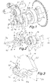
- Dier Erfindung wird im Folgenden an Hand des in den Figuren dargestellten, nicht einschränkenden Ausführungsbeispiels näher erläutert. Darin zeigen:
- Fig. 1
- eine erfindungsgemäße variable Ventiltriebvorrichtung in einer axonometrischen Darstellung;
- Fig. 2
- die Ventiltriebvorrichtung in einer Explosionsdarstellung;
- Fig. 3
- ein Nockenelement der Ventiltriebvorrichtung in einer axonometrischen Darstellung;
- Fig. 4
- die Ventiltriebvorrichtung in einer ersten Stellung des Nockenelementes in einer geschnittenen Darstellung; und
- Fig. 5
- die Ventiltriebvorrichtung in einer zweiten Stellung des Nockenelementes in einer geschnittenen Darstellung.
-
Fig. 1 zeigt eine variable Ventiltriebvorrichtung 1 zur Betätigung zumindest eines - nicht weiter dargestellten - Gaswechselventiles einer Brennkraftmaschine. Die Ventilbetätigungseinrichtung 1 weist eine um eine Drehachse 2a drehbar gelagerte Nockenwelle 2 mit zumindest einem über eine Verstellvorrichtung 20 verstellbaren Nockenelement 3 auf. Das Nockenelement 3 ist zwischen einer eingeklappten ersten Stellung A (Fig. 4 ) und einer ausgeklappten zweiten Stellung B (Fig. 5 ) schwenkbar um eine Schwenkachse 3a gelagert. Diese Schwenkachse 3a ist parallel zur Drehachse 2a der Nockenwelle 2 ausgerichtet und in einem ersten Abstand a zu dieser auf der Nockenwelle 2 angeordnet. Mit anderen Worten ist das Nockenelement 3 schwenkbar in der Nockenwelle 2 gelagert, wobei die Schwenkachse 3a des Nockenelements 3 parallel zur und in einem ersten Abstand a von der Drehachse 2a der Nockenwelle 2 verläuft. - Das verstellbare Nockenelement 3 ist in Richtung der Drehachse 2a der Nockenwelle 2 benachbart zu zwei Basisnocken 4a, 4b eines Nockenkörpers 4 angeordnet. Der Nockenkörper 4 weist dabei eine Aufnahme 5 aus, in der das Nockenelement 3 überwiegend aufgenommen ist und in welche das Nockenelement 3 eingeschwenkt werden kann.
- Mit Bezugszeichen 21 ist ein Nockenfolgeelement, beispielsweise ein Kipphebel bezeichnet, welcher über eine Rolle 22 am Basisnocken 4a, 4b oder am Nockenelement 3 anliegt und entsprechend der Nockenkontur des Basisnockens 4a, 4b oder des Nockenelements 3 ausgelenkt wird. Das Nockenfolgeelement 21 wirkt auf zumindest ein nicht dargestelltes Gaswechselventil der Brennkraftmaschine ein und steuert dessen Hub.
- Die Verstellvorrichtung 20 weist zumindest eine innerhalb der Nockenwelle 2 verschiebbar angeordnete Schubstange 6 mit im Wesentlichen zylindrischer Form auf, wobei die Schubstange 6 zwischen einer ersten Schubstellung A1 und einer zweiten Schubstellung B1 axial - also parallel zur Drehachse 2a der Nockenwelle 2 - verschoben werden kann. Die erste Schubstellung A1 korrespondiert dabei mit der ersten Stellung A des Nockenelementes 3. Die zweite Schubstellung B1 korrespondiert mit der zweiten Stellung B des Nockenelementes 3. Die Schubstange 6 ist im Ausführungsbeispiel zylindrisch ausgebildet, es ist aber auch eine prismatische oder andere Form möglich. Die Schubstange 6 ist achsgleich zur Nockenwelle 2 angeordnet - die Längsachse 6a der Schubstange 6 fällt also mit der Drehachse 2a der Nockenwelle 2 zusammen.
- Die Schubstange 6 weist eine parallel zur Drehachse 2a der Nockenwelle 2 ausgebildete Anschlagfläche 7 für das Nockenelement 3 auf. Die Anschlagfläche 7 ist durch die zylindrische Mantelfläche der Schubstange 6 gebildet und dient als Anschlag für das Nockenelement 3 in der ausgeklappten zweiten Stellung. Durch die Anschlagfläche 7 wird also ein Zurückschwenken des ausgeschwenkten Nockenelementes 3 von der zweiten Stellung B in die erste Stellung A verhindert
- Weiters weist die Schubstange 6 eine geneigt zur Drehachse 2a der Nockenwelle 2 ausgebildete Rampenfläche 8 auf. Die Rampenfläche 8 dient dazu, um die axiale Bewegung der Schubstange 6 in eine radiale Ausschwenkbewegung des Nockenelements 3 zu transferieren und das Nockenelement 3 von der ersten Stellung A in die zweite Stellung B zu bewegen.
- Die Rampenfläche 8 ist auf einer ersten Stirnseite 9 der Schubstange 6 angeordnet. Die Verschiebung der Schubstange 6 erfolgt über einen mit Bezugszeichen 11 in
Fig. 1 ,Fig. 4 und Fig. 5 angedeuteten Aktuator - z.B. hydraulisch, pneumatisch, elektrisch, elektromagnetisch oder anders aktuierbar -, welcher beispielsweise an einer der ersten Stirnseite 9 abgewandten zweiten Stirnseite 10 der Schubstange angreift. - Im Ausführungsbeispiel erstreckt sich die Rampenfläche 8 über die gesamte Stirnfläche der ersten Stirnseite 9 der Schubstange 6.
- Die Rampenfläche 8 ist im Ausführungsbeispiel räumlich gekrümmt und beispielsweise durch eine Rotationsfläche - etwa eine Kegelfläche - gebildet. Die Rampenfläche 8 kann zumindest zwei Bereiche 8a, 8b mit unterschiedlichen Neigungen in Bezug zur Längsachse 6a der Schubstange 6 bzw. Drehachse 2a der Nockenwelle 2 aufweisen. Vorzugsweise ist dabei zwischen den zwei Bereichen 8a, 8b unterschiedlicher Neigung ein stetiger Übergang ausgeführt. Der Neigungswinkel β zwischen der Rampenfläche 8 (bzw. zumindest einem der zwei Bereiche 8a, 8b) und der Drehachse 2a der Nockenwelle 2 (eingezeichnet in
Fig. 5 als Winkel zwischen der Drehachse 2a und einer der Rampenfläche 8 folgenden strichpunktierten Linie) beträgt beispielsweise zwischen etwa 30° und 60°. Die Rampenfläche 8 ist günstigerweise symmetrisch zu einer die Längsachse 6a der Schubstange 6 beinhaltenden Längsebene 6b der Schubstange 6 ausgebildet. - Wie insbesondere aus
Fig. 3 hervorgeht, weist das Nockenelement 3 eine Gegenanschlagfläche 12 auf, welche in der zweiten Stellung B des Nockenelementes 3 auf der Anschlagfläche 7 der Schubstange 6 aufliegt. Die Gegenanschlagfläche 12 ist beispielsweise - analog zur Anschlagfläche 7 der Schubstange 6 - zylindrisch geformt. - Das Nockenelement 3 weist eine Gegenrampenfläche 13 auf, auf welche die Rampenfläche 8 der Schubstange 6 bei der Verstellung von der ersten Stellung A in die zweite Stellung B einwirkt. Die Gegenrampenfläche 13 ist entsprechend der Rampenfläche 8 geneigt, wobei die Form der Gegenrampenfläche 13 mit der Form der Rampenfläche 8 korrespondiert. Die Gegenrampenfläche 13 kann - wie die Rampenfläche 8 - zumindest zwei Abschnitte 13a, 13b mit unterschiedlichen Neigungen aufweisen, zwischen denen vorzugsweise ein stetiger Übergang ausgeführt ist. Der Neigungswinkel γ der Gegenrampenfläche 13 zur Drehachse 2a der Nockenwelle 2 (eingezeichnet in
Fig. 5 als Winkel zwischen der Drehachse 2a und einer der Gegenrampenfläche 13 folgenden strichpunktierten Linie) beträgt ebenfalls zwischen 30° und 60°. Im Ausführungsbeispiel ist die Gegenrampenfläche 13 axial benachbart zur Gegenanschlagfläche 12 und konzentrisch zur Gegenanschlagfläche 12 angeordnet. Im Ausführungsbeispiel ist die Gegenrampenfläche 13 als etwa konische Anfasung im axialen Anschluss an die zylindrische Gegenanschlagfläche 12 ausgebildet. Die Kegelfläche der Gegenrampenfläche 13 und die Zylinderfläche der Gegenanschlagfläche 12 weisen also die gleiche Achse 12a auf. Die räumlichen Konturen der Rampenfläche 8 und der Gegenrampenfläche 13 haben den Vorteil, dass die Berührung zwischen Rampenfläche 8 und Gegenrampenfläche 13 bei Auslenkung des Nockenelements 3 über eine Kontaktfläche und nicht nur - wie bei einer ebenen Rampenfläche - über zwei Kontaktpunkte, oder Kontaktlinien - oder gar nur einen Kontaktpunkt - erfolgt. - Die Neigungen der Rampenfläche 8 und der korrespondierenden Gegenrampenfläche 13 bewirken, dass diese beim Verschieben der Schubstange 6 von der ersten Schubstellung A1 in die zweite Schubstellung B1 ruckfrei und ohne Verhaken aufeinander gleiten. Daher sind vorzugsweise zumindest diejenigen Bereiche der Rampenfläche 8 und der Gegenrampenfläche 13, die bei bestimmungsgemäßer Verwendung der Ventilvorrichtung 1 zusammenwirken, mit korrespondierenden Neigungen ausgeführt.
- Ein Verklemmen oder Verspannen der sich berührenden Teile wird somit vermieden. Zusammen mit dem erwähnten Neigungswinkeln β, γ der Rampenfläche 8 und der Gegenrampenfläche 13 wird außerdem bewirkt, dass Fehlschaltungen und ungewünschte Zwischenstellungen des Nockenelementes 3 zwischen der ersten Stellung A und der zweiten Stellung B vermieden werden. Ist die Bewegung der Schubstange 6 von der ersten Schubstellung A1 in die zweite Schubstellung B1 unvollkommen oder wird dazwischen abgebrochen, so kann die Schubstange 6 über die Rampenfläche 8 und die Gegenrampenfläche 13 durch das Nockenelement 3 wieder zurück in die erste Schubstellung A1 bewegt werden. Voraussetzung ist, dass die Neigungswinkeln β, γ der Rampenfläche 8 und der Gegenrampenfläche 13 in Bezug zur Drehachse 2a der Nockenwelle 2 groß genug ausgeführt sind, um eine Selbsthemmung zu vermeiden.
- Das Nockenelement 3 weist eine Hubfläche 14 auf, welche im Ausführungsbeispiel etwa symmetrisch zu einer Nockenelementlängsebene 3b ausgebildet ist, die durch die Achse 12a der Zylinderfläche der Gegenanschlagfläche 12 bzw. der Kegelfläche der Gegenrampenfläche 13 verläuft. Die Schwenkachse 3a des Nockenelements 3 befindet sich auf einer Seite der Nockenelementlängsebene 3b im Bereich der Hubfläche 14, insbesondere in einem Bereich zwischen der Hubfläche 14 und der Gegenrampenfläche 13.
- In einem zweiten Abstand b zur Schwenkachse 3a weist das Nockenelement 3 an zumindest einer Seitenflanke 3c, 3d - bevorzugt jeweils an beiden Seitenflanken - eine nutartige Ausnehmung 15 mit einer Begrenzungsfläche 16 auf. Die Breite d der nutartigen Ausnehmung 15 ist dabei mindestens so groß wie der Durchmesser D eines durch einen Begrenzungsstift gebildeten Begrenzungselementes 17, welches fest mit der Nockenwelle 2 verbunden ist. Der Begrenzungsstift ist in eine Bohrung 18 der Nockenwelle 2 parallel zur Drehachse 2a der Nockenwelle 2 eingesetzt. Durch das Begrenzungselement 17 wird die Ausschwenkbewegung des Nockenelementes 3 begrenzt, sodass Schäden und ungewünschte Geräuschentwicklung vermieden werden. Auch eine umgekehrte Ausführung, bei der also die nutartige Ausnehmung in der Nockenwelle 2 und das Begrenzungselement im Nockenelement 3 ausgeführt sind, ist möglich.
- Das Nockenelement 3 ist durch ein durch eine Torsionsfeder gebildetes Rückstellelement 19 in Richtung der ersten Stellung A vorgespannt (siehe
Fig. 2 ).Fig. 4 zeigt das Nockenelement 3 in der durch das Rückstellelement 19 bewirkten eingeschwenkten ersten Stellung A, wobei sich die Schubstange 6 in der ersten Schubstellung A1 befindet, welche der Ruhestellung entspricht. - Wird die Schubstange 6 durch den Aktuator 11 von der ersten Schubstellung A1 in die zweite Schubstellung B1 bewegt, so wird durch die Rampenfläche 8 und die Gegenrampenfläche 13 das Nockenelement 3 in die in
Fig. 5 dargestellte zweite Stellung B ausgeschwenkt. In der zweiten Stellung B findet - in Richtung der Drehachse 2a der Nockenwelle 2 betrachtet - eine vollständige Überdeckung der Kontur der Basisnocken 4a, 4b durch die Kontur des Nockenelementes 3 statt. - Sobald die Schubstange 3 wieder von der in
Fig. 5 gezeigten zweiten Schubstellung B1 in die inFig. 4 dargestellte erste Schubstellung A1 zurückgezogen wird, wird das Nockenelement 3 durch das Rückstellelement 19 wieder in die erste Stellung A zurückgeschwenkt. - Die erfindungsgemäße Lösung erlaubt damit die Realisierung von unterschiedlichen Ventilhebekurven auf einfache und verschleiß- und fehlerarme Weise.
Claims (16)
- Variable Ventiltriebvorrichtung (1) zur Betätigung zumindest eines Gaswechselventiles einer Brennkraftmaschine, mit einer um eine Drehachse (2a) drehbar gelagerten Nockenwelle (2) mit zumindest einem über eine Verstellvorrichtung (20) verstellbaren Nockenelement (3), wobei das Nockenelement (3) zwischen zumindest einer eingeklappten ersten Stellung (A) und einer ausgeklappten zweiten Stellung (B) schwenkbar um eine Schwenkachse (3a) gelagert ist, welche parallel zur Drehachse (2a) verlaufend und in einem ersten Abstand (a) zu dieser auf der Nockenwelle (2) angeordnet ist, und wobei das verstellbare Nockenelement (3) in Richtung der Drehachse (2a) der Nockenwelle (2) benachbart zu zumindest einem starr mit der Nockenwelle (2) verbundenen Basisnocken (4a, 4b) angeordnet ist, wobei die Verstellvorrichtung (20) zumindest eine innerhalb der Nockenwelle (2) zwischen zumindest einer ersten Schubstellung (A1) und einer zweiten Schubstellung (B1) verschiebbar angeordnete Schubstange (6) aufweist, wobei die Schubstange (6) zumindest eine vorzugsweise parallel zur Drehachse (2a) der Nockenwelle (2) ausgebildete Anschlagfläche (7) für das Nockenelement (3) und zumindest eine zumindest teilweise geneigt zur Drehachse (2a) der Nockenwelle (2) ausgebildete Rampenfläche (8) aufweist, dadurch gekennzeichnet, dass das Nockenelement (3) eine mit der Rampenfläche (8) der Schubstange (6) zusammenwirkende Gegenrampenfläche (13) aufweist, welche zumindest teilweise geneigt zur Drehachse (2a) der Nockenwelle (2) ausgebildet ist, wobei die Rampenfläche (8) auf einer Stirnseite (9) der Schubstange (6) angeordnet ist.
- Ventiltriebvorrichtung (1) nach Anspruch 1, dadurch gekennzeichnet, dass das Nockenelement (3) mit der Schubstange (6) in zumindest einer Schubstellung (A1, B1) direkt kontaktierbar ist, sodass die Schubstange (6) unmittelbar auf das Nockenelement (3) einwirkt.
- Ventiltriebvorrichtung (1) nach Anspruch 1 oder 2, dadurch gekennzeichnet, dass die Rampenfläche (8) sich über die gesamte Stirnfläche der Stirnseite (9) erstreckt.
- Ventiltriebvorrichtung (1) nach einem der Ansprüche 1 bis 3, dadurch gekennzeichnet, dass die Rampenfläche (8) zumindest zwei Bereiche (8a, 8b) mit unterschiedlichen Neigungswinkeln (β) in Bezug auf die Drehachse (2a) der Nockenwelle (2) aufweist.
- Ventiltriebvorrichtung (1) nach einem der Ansprüche 1 bis 4, dadurch gekennzeichnet, dass die Rampenfläche (8) zumindest abschnittsweise räumlich gekrümmt ist und vorzugsweise durch eine Rotationsfläche gebildet ist.
- Ventiltriebvorrichtung (1) nach Anspruch 5, dadurch gekennzeichnet, dass die Rampenfläche (8) durch eine Kegelfläche gebildet ist.
- Ventiltriebvorrichtung (1) nach einem der Ansprüche 1 bis 6, dadurch gekennzeichnet, dass die Gegenrampenfläche (13) des Nockenelements (3) zumindest abschnittsweise räumlich gekrümmt ist.
- Ventiltriebvorrichtung (1) nach einem der Ansprüche 1 bis 7, dadurch gekennzeichnet, dass die Gegenrampenfläche (13) des Nockenelements (3) zumindest zwei Abschnitte (13a, 13b) mit unterschiedlichen Neigungswinkeln (γ) in Bezug auf die Drehachse (2a) der Nockenwelle (2) aufweist.
- Ventiltriebvorrichtung (1) nach einem der Ansprüche 1 bis 8, dadurch gekennzeichnet, dass die Rampenfläche (8) und/oder die Gegenrampenfläche (13) zumindest abschnittsweise unter einem Neigungswinkel (β, γ) zwischen etwa 30° und 60° zur Drehachse (2a) der Nockenwelle (2) geneigt ist/sind.
- Ventiltriebvorrichtung (1) nach einem der Ansprüche 1 bis 9, dadurch gekennzeichnet, dass das Nockenelement (3) eine mit der Anschlagfläche (7) der Schubstange (6) zusammenwirkende Gegenanschlagfläche (12) aufweist, welche vorzugsweise zylindrisch ausgebildet ist.
- Ventiltriebvorrichtung (1) nach Anspruch 10, dadurch gekennzeichnet, dass die Gegenanschlagfläche (12) - in Bezug auf die Drehachse (2a) der Nockenwelle (2) - axial benachbart zur Gegenrampenfläche (13) angeordnet ist.
- Ventiltriebvorrichtung (1) nach Anspruch 10 oder 11, dadurch gekennzeichnet, dass die Gegenrampenfläche (13) als Anfasung um die Gegenanschlagfläche (12) ausgebildet ist.
- Ventiltriebvorrichtung (1) nach einem der Ansprüche 1 bis 12, dadurch gekennzeichnet, dass das Nockenelement (3) durch ein Rückstellelement (19), das vorzugsweise durch eine Torsionsfeder gebildet ist, in Richtung der ersten Stellung (A) vorgespannt ist.
- Ventiltriebvorrichtung (1) nach einem der Ansprüche 1 bis 13, dadurch gekennzeichnet, dass zumindest ein fest mit der Nockenwelle (2) verbundenes Begrenzungselement (17) vorgesehen ist, wobei das Nockenelement (3) eine mit dem Begrenzungselement (17) korrespondierende Begrenzungsfläche (16) aufweist, wobei die Begrenzungsfläche (16) des Nockenelementes (3) bei einer maximalen Ausschwenklage des Nockenelementes (3) am Begrenzungselement (17) anliegt.
- Ventiltriebvorrichtung (1) nach Anspruch 14, dadurch gekennzeichnet, dass das Begrenzungselement (17) als Begrenzungsstift ausgeführt ist.
- Ventiltriebvorrichtung (1) nach einem der Ansprüche 1 bis 15, dadurch gekennzeichnet, dass das Nockenelement (3) in der zweiten Stellung (B) die Kontur zumindest eines Basisnockens (4a, 4b), vorzugsweise zweier axial an das Nockenelement (3) beidseitig anschließender Basisnocken (4a, 4b) - in Richtung der Drehachse (2a) der Nockenwelle (2) betrachtet - vollständig überdeckt.
Applications Claiming Priority (2)
| Application Number | Priority Date | Filing Date | Title |
|---|---|---|---|
| ATA50612/2018A AT521559B1 (de) | 2018-07-16 | 2018-07-16 | Variable ventiltriebvorrichtung |
| PCT/AT2019/060237 WO2020014722A1 (de) | 2018-07-16 | 2019-07-16 | Variable ventiltriebvorrichtung |
Publications (2)
| Publication Number | Publication Date |
|---|---|
| EP3824165A1 EP3824165A1 (de) | 2021-05-26 |
| EP3824165B1 true EP3824165B1 (de) | 2022-03-30 |
Family
ID=67441058
Family Applications (1)
| Application Number | Title | Priority Date | Filing Date |
|---|---|---|---|
| EP19745032.3A Active EP3824165B1 (de) | 2018-07-16 | 2019-07-16 | Variable ventiltriebvorrichtung |
Country Status (3)
| Country | Link |
|---|---|
| EP (1) | EP3824165B1 (de) |
| AT (1) | AT521559B1 (de) |
| WO (1) | WO2020014722A1 (de) |
Citations (3)
| Publication number | Priority date | Publication date | Assignee | Title |
|---|---|---|---|---|
| DE69421170T2 (de) * | 1993-12-17 | 2000-07-06 | Christos Valasopoulos | Nockenspitze mit exzentrischer drehbewegung |
| WO2002081872A1 (en) * | 2001-04-05 | 2002-10-17 | Stephen William Mitchell | Variable valve timing system |
| EP3045690B1 (de) * | 2015-01-15 | 2019-03-27 | Toyota Jidosha Kabushiki Kaisha | Variable ventilvorrichtung für einen verbrennungsmotor |
Family Cites Families (7)
| Publication number | Priority date | Publication date | Assignee | Title |
|---|---|---|---|---|
| FR322489A (fr) * | 1902-06-25 | 1903-02-06 | Des Anciens Etablissements Panhard Et Levassor | Perfectionnement dans la construction des moteurs à explosion |
| FR569928A (fr) * | 1923-08-20 | 1924-04-19 | Dispositif de commande de cames | |
| US5855190A (en) * | 1996-09-24 | 1999-01-05 | Yamaha Hatsudoki Kabushiki Kaisha | Valve-actuating variable cam for engine |
| DE20320710U1 (de) * | 2002-03-28 | 2005-02-10 | Battlogg, Stefan | Vorrichtung zur Umwandlung einer Drehbewegung in eine hin- und hergehende Bewegung |
| DE10242235A1 (de) * | 2002-09-12 | 2004-03-25 | Daimlerchrysler Ag | Bremsventilsystem für eine Nockenwelle |
| JP6252528B2 (ja) | 2015-03-19 | 2017-12-27 | トヨタ自動車株式会社 | 内燃機関の可変動弁装置 |
| JP6295991B2 (ja) | 2015-04-09 | 2018-03-20 | トヨタ自動車株式会社 | 内燃機関の可変動弁装置 |
-
2018
- 2018-07-16 AT ATA50612/2018A patent/AT521559B1/de active
-
2019
- 2019-07-16 EP EP19745032.3A patent/EP3824165B1/de active Active
- 2019-07-16 WO PCT/AT2019/060237 patent/WO2020014722A1/de not_active Ceased
Patent Citations (3)
| Publication number | Priority date | Publication date | Assignee | Title |
|---|---|---|---|---|
| DE69421170T2 (de) * | 1993-12-17 | 2000-07-06 | Christos Valasopoulos | Nockenspitze mit exzentrischer drehbewegung |
| WO2002081872A1 (en) * | 2001-04-05 | 2002-10-17 | Stephen William Mitchell | Variable valve timing system |
| EP3045690B1 (de) * | 2015-01-15 | 2019-03-27 | Toyota Jidosha Kabushiki Kaisha | Variable ventilvorrichtung für einen verbrennungsmotor |
Also Published As
| Publication number | Publication date |
|---|---|
| AT521559B1 (de) | 2022-08-15 |
| EP3824165A1 (de) | 2021-05-26 |
| AT521559A1 (de) | 2020-02-15 |
| WO2020014722A1 (de) | 2020-01-23 |
Similar Documents
| Publication | Publication Date | Title |
|---|---|---|
| EP3170997B1 (de) | Variabler ventiltrieb mit einem kipphebel | |
| DE60304621T2 (de) | Kipphebel zur zweistufigen Nockenbetätigung | |
| EP2396522B1 (de) | Ventiltrieb einer brennkraftmaschine | |
| DE19700316C2 (de) | Schwinghebelanordnung | |
| DE69805352T2 (de) | Auf zwei unterschiedliche Ventilhübe schaltbare Ventilbetätigungsvorrichtung | |
| DE4230877A1 (de) | Ventilsteuerung fuer ein hubventil mit zwei nocken | |
| EP2126292A1 (de) | Ventiltrieb für gaswechselventile einer brennkraftmaschine mit einem axial beweglichen lager | |
| WO2008107111A1 (de) | Ventiltrieb für gaswechselventile einer brennkraftmaschine mit verschiebbarem nockenträger und doppelschneckentrieb | |
| DE112017004565T5 (de) | Dreirollenkipphebel mit abpumpanschlag | |
| DE4220816A1 (de) | Variable Ventilsteuerung mittels Änderung der Hebelverhältnisse bei Kipp- oder Schlepphebeln von Ventiltrieben | |
| WO2011026562A1 (de) | Ventiltrieb für gaswechselventile einer brennkraftmaschine mit axial verschiebbaren nockeneinheiten | |
| DE112018005349T5 (de) | Doppelhub-kipphebel mit zusätzlicher bewegung | |
| DE19828945C2 (de) | Vorrichtung zum Aktivieren und Deaktivieren eines Ladungswechselventils einer Brennkraftmaschine | |
| EP1913240A1 (de) | Schaltbarer ventilbetätigungsmechanismus | |
| EP3067524A1 (de) | Stellelement zum axialen verschieben einer entlang einer nockenwellenachse verschiebbar gelagerten nockenwelle | |
| DE102008008094B3 (de) | Ventilhebelbaugruppe mit einem schaltbaren Ventilbetätigungsmechanismus | |
| DE4405189C2 (de) | Stößel für ein abschaltbares Ventil einer Brennkraftmaschine | |
| DE69923139T2 (de) | Schlepphebelanordnung für gleichzeitige Ventil-Hub und Winkelsteuerung in einer Brennkraftmaschine | |
| DE102012012150B4 (de) | Schlepphebelanordnung und Verbrennungsmotor | |
| EP1205643A1 (de) | Ventieltrieb für eine Verbrennungskraftmaschine | |
| EP3824165B1 (de) | Variable ventiltriebvorrichtung | |
| EP3173593A1 (de) | Variabler ventiltrieb mit einem kipphebel | |
| DE19830168C2 (de) | Vorrichtung zum Aktivieren und Deaktivieren eines Ladungswechselventils einer Brennkraftmaschine | |
| AT521668B1 (de) | Variable ventiltriebvorrichtung | |
| DE102008031992A1 (de) | Vorrichtung zum Verstellen und Arretieren einer Exzenterbuchse in einem Lagerauge eines Pleuels einer Brennkraftmaschine |
Legal Events
| Date | Code | Title | Description |
|---|---|---|---|
| STAA | Information on the status of an ep patent application or granted ep patent |
Free format text: STATUS: UNKNOWN |
|
| STAA | Information on the status of an ep patent application or granted ep patent |
Free format text: STATUS: THE INTERNATIONAL PUBLICATION HAS BEEN MADE |
|
| PUAI | Public reference made under article 153(3) epc to a published international application that has entered the european phase |
Free format text: ORIGINAL CODE: 0009012 |
|
| STAA | Information on the status of an ep patent application or granted ep patent |
Free format text: STATUS: REQUEST FOR EXAMINATION WAS MADE |
|
| 17P | Request for examination filed |
Effective date: 20210112 |
|
| AK | Designated contracting states |
Kind code of ref document: A1 Designated state(s): AL AT BE BG CH CY CZ DE DK EE ES FI FR GB GR HR HU IE IS IT LI LT LU LV MC MK MT NL NO PL PT RO RS SE SI SK SM TR |
|
| DAV | Request for validation of the european patent (deleted) | ||
| DAX | Request for extension of the european patent (deleted) | ||
| GRAP | Despatch of communication of intention to grant a patent |
Free format text: ORIGINAL CODE: EPIDOSNIGR1 |
|
| STAA | Information on the status of an ep patent application or granted ep patent |
Free format text: STATUS: GRANT OF PATENT IS INTENDED |
|
| INTG | Intention to grant announced |
Effective date: 20211022 |
|
| GRAS | Grant fee paid |
Free format text: ORIGINAL CODE: EPIDOSNIGR3 |
|
| GRAA | (expected) grant |
Free format text: ORIGINAL CODE: 0009210 |
|
| STAA | Information on the status of an ep patent application or granted ep patent |
Free format text: STATUS: THE PATENT HAS BEEN GRANTED |
|
| AK | Designated contracting states |
Kind code of ref document: B1 Designated state(s): AL AT BE BG CH CY CZ DE DK EE ES FI FR GB GR HR HU IE IS IT LI LT LU LV MC MK MT NL NO PL PT RO RS SE SI SK SM TR |
|
| REG | Reference to a national code |
Ref country code: GB Ref legal event code: FG4D Free format text: NOT ENGLISH |
|
| REG | Reference to a national code |
Ref country code: CH Ref legal event code: EP |
|
| REG | Reference to a national code |
Ref country code: AT Ref legal event code: REF Ref document number: 1479382 Country of ref document: AT Kind code of ref document: T Effective date: 20220415 |
|
| REG | Reference to a national code |
Ref country code: DE Ref legal event code: R096 Ref document number: 502019003903 Country of ref document: DE |
|
| REG | Reference to a national code |
Ref country code: IE Ref legal event code: FG4D Free format text: LANGUAGE OF EP DOCUMENT: GERMAN |
|
| REG | Reference to a national code |
Ref country code: LT Ref legal event code: MG9D |
|
| PG25 | Lapsed in a contracting state [announced via postgrant information from national office to epo] |
Ref country code: SE Free format text: LAPSE BECAUSE OF FAILURE TO SUBMIT A TRANSLATION OF THE DESCRIPTION OR TO PAY THE FEE WITHIN THE PRESCRIBED TIME-LIMIT Effective date: 20220330 Ref country code: RS Free format text: LAPSE BECAUSE OF FAILURE TO SUBMIT A TRANSLATION OF THE DESCRIPTION OR TO PAY THE FEE WITHIN THE PRESCRIBED TIME-LIMIT Effective date: 20220330 Ref country code: NO Free format text: LAPSE BECAUSE OF FAILURE TO SUBMIT A TRANSLATION OF THE DESCRIPTION OR TO PAY THE FEE WITHIN THE PRESCRIBED TIME-LIMIT Effective date: 20220630 Ref country code: LT Free format text: LAPSE BECAUSE OF FAILURE TO SUBMIT A TRANSLATION OF THE DESCRIPTION OR TO PAY THE FEE WITHIN THE PRESCRIBED TIME-LIMIT Effective date: 20220330 Ref country code: HR Free format text: LAPSE BECAUSE OF FAILURE TO SUBMIT A TRANSLATION OF THE DESCRIPTION OR TO PAY THE FEE WITHIN THE PRESCRIBED TIME-LIMIT Effective date: 20220330 Ref country code: BG Free format text: LAPSE BECAUSE OF FAILURE TO SUBMIT A TRANSLATION OF THE DESCRIPTION OR TO PAY THE FEE WITHIN THE PRESCRIBED TIME-LIMIT Effective date: 20220630 |
|
| REG | Reference to a national code |
Ref country code: NL Ref legal event code: MP Effective date: 20220330 |
|
| PG25 | Lapsed in a contracting state [announced via postgrant information from national office to epo] |
Ref country code: LV Free format text: LAPSE BECAUSE OF FAILURE TO SUBMIT A TRANSLATION OF THE DESCRIPTION OR TO PAY THE FEE WITHIN THE PRESCRIBED TIME-LIMIT Effective date: 20220330 Ref country code: GR Free format text: LAPSE BECAUSE OF FAILURE TO SUBMIT A TRANSLATION OF THE DESCRIPTION OR TO PAY THE FEE WITHIN THE PRESCRIBED TIME-LIMIT Effective date: 20220701 Ref country code: FI Free format text: LAPSE BECAUSE OF FAILURE TO SUBMIT A TRANSLATION OF THE DESCRIPTION OR TO PAY THE FEE WITHIN THE PRESCRIBED TIME-LIMIT Effective date: 20220330 |
|
| PG25 | Lapsed in a contracting state [announced via postgrant information from national office to epo] |
Ref country code: NL Free format text: LAPSE BECAUSE OF FAILURE TO SUBMIT A TRANSLATION OF THE DESCRIPTION OR TO PAY THE FEE WITHIN THE PRESCRIBED TIME-LIMIT Effective date: 20220330 |
|
| PG25 | Lapsed in a contracting state [announced via postgrant information from national office to epo] |
Ref country code: SM Free format text: LAPSE BECAUSE OF FAILURE TO SUBMIT A TRANSLATION OF THE DESCRIPTION OR TO PAY THE FEE WITHIN THE PRESCRIBED TIME-LIMIT Effective date: 20220330 Ref country code: SK Free format text: LAPSE BECAUSE OF FAILURE TO SUBMIT A TRANSLATION OF THE DESCRIPTION OR TO PAY THE FEE WITHIN THE PRESCRIBED TIME-LIMIT Effective date: 20220330 Ref country code: RO Free format text: LAPSE BECAUSE OF FAILURE TO SUBMIT A TRANSLATION OF THE DESCRIPTION OR TO PAY THE FEE WITHIN THE PRESCRIBED TIME-LIMIT Effective date: 20220330 Ref country code: PT Free format text: LAPSE BECAUSE OF FAILURE TO SUBMIT A TRANSLATION OF THE DESCRIPTION OR TO PAY THE FEE WITHIN THE PRESCRIBED TIME-LIMIT Effective date: 20220801 Ref country code: ES Free format text: LAPSE BECAUSE OF FAILURE TO SUBMIT A TRANSLATION OF THE DESCRIPTION OR TO PAY THE FEE WITHIN THE PRESCRIBED TIME-LIMIT Effective date: 20220330 Ref country code: EE Free format text: LAPSE BECAUSE OF FAILURE TO SUBMIT A TRANSLATION OF THE DESCRIPTION OR TO PAY THE FEE WITHIN THE PRESCRIBED TIME-LIMIT Effective date: 20220330 Ref country code: CZ Free format text: LAPSE BECAUSE OF FAILURE TO SUBMIT A TRANSLATION OF THE DESCRIPTION OR TO PAY THE FEE WITHIN THE PRESCRIBED TIME-LIMIT Effective date: 20220330 |
|
| PG25 | Lapsed in a contracting state [announced via postgrant information from national office to epo] |
Ref country code: PL Free format text: LAPSE BECAUSE OF FAILURE TO SUBMIT A TRANSLATION OF THE DESCRIPTION OR TO PAY THE FEE WITHIN THE PRESCRIBED TIME-LIMIT Effective date: 20220330 Ref country code: IS Free format text: LAPSE BECAUSE OF FAILURE TO SUBMIT A TRANSLATION OF THE DESCRIPTION OR TO PAY THE FEE WITHIN THE PRESCRIBED TIME-LIMIT Effective date: 20220730 Ref country code: AL Free format text: LAPSE BECAUSE OF FAILURE TO SUBMIT A TRANSLATION OF THE DESCRIPTION OR TO PAY THE FEE WITHIN THE PRESCRIBED TIME-LIMIT Effective date: 20220330 |
|
| REG | Reference to a national code |
Ref country code: DE Ref legal event code: R097 Ref document number: 502019003903 Country of ref document: DE |
|
| PG25 | Lapsed in a contracting state [announced via postgrant information from national office to epo] |
Ref country code: DK Free format text: LAPSE BECAUSE OF FAILURE TO SUBMIT A TRANSLATION OF THE DESCRIPTION OR TO PAY THE FEE WITHIN THE PRESCRIBED TIME-LIMIT Effective date: 20220330 |
|
| PLBE | No opposition filed within time limit |
Free format text: ORIGINAL CODE: 0009261 |
|
| STAA | Information on the status of an ep patent application or granted ep patent |
Free format text: STATUS: NO OPPOSITION FILED WITHIN TIME LIMIT |
|
| PG25 | Lapsed in a contracting state [announced via postgrant information from national office to epo] |
Ref country code: MC Free format text: LAPSE BECAUSE OF FAILURE TO SUBMIT A TRANSLATION OF THE DESCRIPTION OR TO PAY THE FEE WITHIN THE PRESCRIBED TIME-LIMIT Effective date: 20220330 |
|
| REG | Reference to a national code |
Ref country code: CH Ref legal event code: PL |
|
| 26N | No opposition filed |
Effective date: 20230103 |
|
| REG | Reference to a national code |
Ref country code: BE Ref legal event code: MM Effective date: 20220731 |
|
| PG25 | Lapsed in a contracting state [announced via postgrant information from national office to epo] |
Ref country code: LU Free format text: LAPSE BECAUSE OF NON-PAYMENT OF DUE FEES Effective date: 20220716 Ref country code: LI Free format text: LAPSE BECAUSE OF NON-PAYMENT OF DUE FEES Effective date: 20220731 Ref country code: FR Free format text: LAPSE BECAUSE OF NON-PAYMENT OF DUE FEES Effective date: 20220731 Ref country code: CH Free format text: LAPSE BECAUSE OF NON-PAYMENT OF DUE FEES Effective date: 20220731 |
|
| PG25 | Lapsed in a contracting state [announced via postgrant information from national office to epo] |
Ref country code: SI Free format text: LAPSE BECAUSE OF FAILURE TO SUBMIT A TRANSLATION OF THE DESCRIPTION OR TO PAY THE FEE WITHIN THE PRESCRIBED TIME-LIMIT Effective date: 20220330 Ref country code: BE Free format text: LAPSE BECAUSE OF NON-PAYMENT OF DUE FEES Effective date: 20220731 |
|
| P01 | Opt-out of the competence of the unified patent court (upc) registered |
Effective date: 20230502 |
|
| PG25 | Lapsed in a contracting state [announced via postgrant information from national office to epo] |
Ref country code: IT Free format text: LAPSE BECAUSE OF FAILURE TO SUBMIT A TRANSLATION OF THE DESCRIPTION OR TO PAY THE FEE WITHIN THE PRESCRIBED TIME-LIMIT Effective date: 20220330 Ref country code: IE Free format text: LAPSE BECAUSE OF NON-PAYMENT OF DUE FEES Effective date: 20220716 |
|
| GBPC | Gb: european patent ceased through non-payment of renewal fee |
Effective date: 20230716 |
|
| PG25 | Lapsed in a contracting state [announced via postgrant information from national office to epo] |
Ref country code: MK Free format text: LAPSE BECAUSE OF FAILURE TO SUBMIT A TRANSLATION OF THE DESCRIPTION OR TO PAY THE FEE WITHIN THE PRESCRIBED TIME-LIMIT Effective date: 20220330 Ref country code: CY Free format text: LAPSE BECAUSE OF FAILURE TO SUBMIT A TRANSLATION OF THE DESCRIPTION OR TO PAY THE FEE WITHIN THE PRESCRIBED TIME-LIMIT Effective date: 20220330 Ref country code: GB Free format text: LAPSE BECAUSE OF NON-PAYMENT OF DUE FEES Effective date: 20230716 |
|
| PG25 | Lapsed in a contracting state [announced via postgrant information from national office to epo] |
Ref country code: HU Free format text: LAPSE BECAUSE OF FAILURE TO SUBMIT A TRANSLATION OF THE DESCRIPTION OR TO PAY THE FEE WITHIN THE PRESCRIBED TIME-LIMIT; INVALID AB INITIO Effective date: 20190716 |
|
| PG25 | Lapsed in a contracting state [announced via postgrant information from national office to epo] |
Ref country code: MT Free format text: LAPSE BECAUSE OF FAILURE TO SUBMIT A TRANSLATION OF THE DESCRIPTION OR TO PAY THE FEE WITHIN THE PRESCRIBED TIME-LIMIT Effective date: 20220330 |
|
| REG | Reference to a national code |
Ref country code: AT Ref legal event code: MM01 Ref document number: 1479382 Country of ref document: AT Kind code of ref document: T Effective date: 20240716 |
|
| PGFP | Annual fee paid to national office [announced via postgrant information from national office to epo] |
Ref country code: DE Payment date: 20250728 Year of fee payment: 7 |
|
| PG25 | Lapsed in a contracting state [announced via postgrant information from national office to epo] |
Ref country code: AT Free format text: LAPSE BECAUSE OF NON-PAYMENT OF DUE FEES Effective date: 20240716 |
|
| PG25 | Lapsed in a contracting state [announced via postgrant information from national office to epo] |
Ref country code: TR Free format text: LAPSE BECAUSE OF FAILURE TO SUBMIT A TRANSLATION OF THE DESCRIPTION OR TO PAY THE FEE WITHIN THE PRESCRIBED TIME-LIMIT Effective date: 20220330 |
|
| PGFP | Annual fee paid to national office [announced via postgrant information from national office to epo] |
Ref country code: AT Payment date: 20260410 Year of fee payment: 5 |