EP3824524B1 - Procédé de vérification d'un point de séparation d'un onduleur photovoltaïque et un tel onduleur photovoltaïque - Google Patents
Procédé de vérification d'un point de séparation d'un onduleur photovoltaïque et un tel onduleur photovoltaïque Download PDFInfo
- Publication number
- EP3824524B1 EP3824524B1 EP19779492.8A EP19779492A EP3824524B1 EP 3824524 B1 EP3824524 B1 EP 3824524B1 EP 19779492 A EP19779492 A EP 19779492A EP 3824524 B1 EP3824524 B1 EP 3824524B1
- Authority
- EP
- European Patent Office
- Prior art keywords
- disconnection point
- switching
- voltages
- phase
- output
- Prior art date
- Legal status (The legal status is an assumption and is not a legal conclusion. Google has not performed a legal analysis and makes no representation as to the accuracy of the status listed.)
- Active
Links
Images

Classifications
-
- G—PHYSICS
- G01—MEASURING; TESTING
- G01R—MEASURING ELECTRIC VARIABLES; MEASURING MAGNETIC VARIABLES
- G01R31/00—Arrangements for testing electric properties; Arrangements for locating electric faults; Arrangements for electrical testing characterised by what is being tested not provided for elsewhere
- G01R31/327—Testing of circuit interrupters, switches or circuit-breakers
- G01R31/3271—Testing of circuit interrupters, switches or circuit-breakers of high voltage or medium voltage devices
- G01R31/3275—Fault detection or status indication
-
- G—PHYSICS
- G01—MEASURING; TESTING
- G01R—MEASURING ELECTRIC VARIABLES; MEASURING MAGNETIC VARIABLES
- G01R31/00—Arrangements for testing electric properties; Arrangements for locating electric faults; Arrangements for electrical testing characterised by what is being tested not provided for elsewhere
- G01R31/40—Testing power supplies
- G01R31/42—AC power supplies
-
- G—PHYSICS
- G01—MEASURING; TESTING
- G01R—MEASURING ELECTRIC VARIABLES; MEASURING MAGNETIC VARIABLES
- G01R31/00—Arrangements for testing electric properties; Arrangements for locating electric faults; Arrangements for electrical testing characterised by what is being tested not provided for elsewhere
- G01R31/005—Testing of electric installations on transport means
- G01R31/006—Testing of electric installations on transport means on road vehicles, e.g. automobiles or trucks
-
- G—PHYSICS
- G01—MEASURING; TESTING
- G01R—MEASURING ELECTRIC VARIABLES; MEASURING MAGNETIC VARIABLES
- G01R31/00—Arrangements for testing electric properties; Arrangements for locating electric faults; Arrangements for electrical testing characterised by what is being tested not provided for elsewhere
- G01R31/327—Testing of circuit interrupters, switches or circuit-breakers
- G01R31/3271—Testing of circuit interrupters, switches or circuit-breakers of high voltage or medium voltage devices
- G01R31/3272—Apparatus, systems or circuits therefor
- G01R31/3274—Details related to measuring, e.g. sensing, displaying or computing; Measuring of variables related to the contact pieces, e.g. wear, position or resistance
-
- G—PHYSICS
- G01—MEASURING; TESTING
- G01R—MEASURING ELECTRIC VARIABLES; MEASURING MAGNETIC VARIABLES
- G01R31/00—Arrangements for testing electric properties; Arrangements for locating electric faults; Arrangements for electrical testing characterised by what is being tested not provided for elsewhere
- G01R31/327—Testing of circuit interrupters, switches or circuit-breakers
- G01R31/3277—Testing of circuit interrupters, switches or circuit-breakers of low voltage devices, e.g. domestic or industrial devices, such as motor protections, relays, rotation switches
- G01R31/3278—Testing of circuit interrupters, switches or circuit-breakers of low voltage devices, e.g. domestic or industrial devices, such as motor protections, relays, rotation switches of relays, solenoids or reed switches
-
- H—ELECTRICITY
- H02—GENERATION; CONVERSION OR DISTRIBUTION OF ELECTRIC POWER
- H02J—ELECTRIC POWER NETWORKS; CIRCUIT ARRANGEMENTS OR SYSTEMS FOR SUPPLYING OR DISTRIBUTING ELECTRIC POWER; SYSTEMS FOR STORING ELECTRIC ENERGY
- H02J3/00—Circuit arrangements for AC mains or AC distribution networks
- H02J3/38—Arrangements for feeding a single network from two or more generators or sources in parallel; Arrangements for feeding already energised networks from additional generators or sources in parallel
- H02J3/381—Dispersed generators
-
- H—ELECTRICITY
- H02—GENERATION; CONVERSION OR DISTRIBUTION OF ELECTRIC POWER
- H02S—GENERATION OF ELECTRIC POWER BY CONVERSION OF INFRARED RADIATION, VISIBLE LIGHT OR ULTRAVIOLET LIGHT, e.g. USING PHOTOVOLTAIC [PV] MODULES
- H02S40/00—Components or accessories in combination with PV modules, not provided for in groups H02S10/00 - H02S30/00
- H02S40/30—Electrical components
- H02S40/32—Electrical components comprising DC/AC inverter means associated with the PV module itself, e.g. AC modules
-
- H—ELECTRICITY
- H02—GENERATION; CONVERSION OR DISTRIBUTION OF ELECTRIC POWER
- H02S—GENERATION OF ELECTRIC POWER BY CONVERSION OF INFRARED RADIATION, VISIBLE LIGHT OR ULTRAVIOLET LIGHT, e.g. USING PHOTOVOLTAIC [PV] MODULES
- H02S50/00—Monitoring or testing of PV systems, e.g. load balancing or fault identification
-
- H—ELECTRICITY
- H01—ELECTRIC ELEMENTS
- H01H—ELECTRIC SWITCHES; RELAYS; SELECTORS; EMERGENCY PROTECTIVE DEVICES
- H01H11/00—Apparatus or processes specially adapted for the manufacture of electric switches
- H01H11/0062—Testing or measuring non-electrical properties of switches, e.g. contact velocity
-
- H—ELECTRICITY
- H01—ELECTRIC ELEMENTS
- H01H—ELECTRIC SWITCHES; RELAYS; SELECTORS; EMERGENCY PROTECTIVE DEVICES
- H01H47/00—Circuit arrangements not adapted to a particular application of the relay and designed to obtain desired operating characteristics or to provide energising current
- H01H47/002—Monitoring or fail-safe circuits
-
- H—ELECTRICITY
- H02—GENERATION; CONVERSION OR DISTRIBUTION OF ELECTRIC POWER
- H02J—ELECTRIC POWER NETWORKS; CIRCUIT ARRANGEMENTS OR SYSTEMS FOR SUPPLYING OR DISTRIBUTING ELECTRIC POWER; SYSTEMS FOR STORING ELECTRIC ENERGY
- H02J2101/00—Supply or distribution of decentralised, dispersed or local electric power generation
- H02J2101/20—Dispersed power generation using renewable energy sources
- H02J2101/22—Solar energy
- H02J2101/24—Photovoltaics
-
- H—ELECTRICITY
- H02—GENERATION; CONVERSION OR DISTRIBUTION OF ELECTRIC POWER
- H02M—APPARATUS FOR CONVERSION BETWEEN AC AND AC, BETWEEN AC AND DC, OR BETWEEN DC AND DC, AND FOR USE WITH MAINS OR SIMILAR POWER SUPPLY SYSTEMS; CONVERSION OF DC OR AC INPUT POWER INTO SURGE OUTPUT POWER; CONTROL OR REGULATION THEREOF
- H02M1/00—Details of apparatus for conversion
- H02M1/32—Means for protecting converters other than automatic disconnection
-
- Y—GENERAL TAGGING OF NEW TECHNOLOGICAL DEVELOPMENTS; GENERAL TAGGING OF CROSS-SECTIONAL TECHNOLOGIES SPANNING OVER SEVERAL SECTIONS OF THE IPC; TECHNICAL SUBJECTS COVERED BY FORMER USPC CROSS-REFERENCE ART COLLECTIONS [XRACs] AND DIGESTS
- Y02—TECHNOLOGIES OR APPLICATIONS FOR MITIGATION OR ADAPTATION AGAINST CLIMATE CHANGE
- Y02E—REDUCTION OF GREENHOUSE GAS [GHG] EMISSIONS, RELATED TO ENERGY GENERATION, TRANSMISSION OR DISTRIBUTION
- Y02E10/00—Energy generation through renewable energy sources
- Y02E10/50—Photovoltaic [PV] energy
- Y02E10/56—Power conversion systems, e.g. maximum power point trackers
Definitions
- the invention relates to a method for testing a separation point of a photovoltaic inverter with an intermediate circuit, the separation point having at least two lines with two switching contacts in series in each line, which switching contacts are controlled accordingly for testing functionality.
- the invention further relates to a photovoltaic inverter for converting a direct voltage into an alternating voltage for feeding the alternating voltage into a supply network and / or for supplying consumers, with an input DC-DC converter, an intermediate circuit, an output DC-AC Converter and a separation point with at least two lines with two switching contacts in series in each line.
- an arrangement of one relay pair per line is used as the separation point between the photovoltaic inverter and the supply network or the consumers, in order to achieve reliable separation from the supply network or the consumer.
- Adherence to the relevant standards and regulations is a prerequisite for approval for grid-parallel feed with inverters without galvanic isolation.
- a separation point from two mutually independent devices for network monitoring with associated switches in series is prescribed. The functionality of the switching points must be checked to ensure that an intact double switch contact set is available before switching on the relays and before starting feed-in operation and that all current-carrying conductors can still be disconnected if a single switch contact is stuck.
- the EP 2 837 012 B1 and the AT 513 866 B1 describe methods for testing a separation point of a photovoltaic inverter and a photovoltaic inverter of the type in question, the switching contacts being switched step by step according to a certain switching pattern and the voltages measured before and after the separation point and the functionality of the measured therefrom Switching contacts is derived. Further prior art is in the EP 2 608 375 A2 , US 2011/298470 A1 , US 2016/268923 A1 , JP 2004 187362 A and US 2016/099569 A1 listed.
- the present invention is applicable to three-phase networks with three phases and a neutral conductor, single-phase networks with one phase and a neutral conductor, but also three-phase networks without a neutral conductor or single-phase networks without a neutral conductor, such as the American split-phase grid or single-phase three-wire network.
- the object of the present invention is to create an above-mentioned method for testing a separation point of a photovoltaic inverter and such a photovoltaic inverter, which can be implemented simply and inexpensively and with the least possible hardware outlay.
- the functionality of the separation point should be able to be checked as quickly as possible and with little measurement effort. Disadvantages of known methods should be avoided or at least reduced.
- the object according to the invention is achieved in that, in a test mode between the input of each line of the separation point and an intermediate circuit potential, an auxiliary voltage generated by the photovoltaic inverter is impressed, the first switching contacts of the separation point are alternately closed and each time corresponding to a switching pattern the second switch contacts are opened and then the second switch contacts are closed and the first switch contacts are opened and the voltages between the output of each line of the isolating point and the intermediate circuit potential are measured for each switching pattern of the switching contacts and from the measured voltages for each switching pattern of the switching contacts the functionality of each switching contact is derived.
- the separation point is tested in test mode using an auxiliary voltage generated by the photovoltaic inverter, in particular its output DC-AC converter, so that the method, in contrast to the prior art, is independent of the presence of a specific mains voltage.
- the test procedure in question can also be used for stand-alone inverters and also for isolated networks and circuits, including emergency circuits, in which the photovoltaic inverter is switched on also no voltage is applied.
- the auxiliary voltage is generated with the existing hardware of the photovoltaic inverter, the hardware outlay is particularly low, so that the method can be carried out very easily and inexpensively.
- a certain sequence is necessary for the execution of the test mode, which can be implemented relatively easily in software in an existing control device of the photovoltaic inverter or in a dedicated control device (e.g. a microprocessor). From the various voltages measured at the intermediate circuit potential, the voltage drop across each switching contact can be calculated for each switching pattern, and from these calculated voltages, conclusions can be drawn about the functionality of the switching contacts and thus the correct functioning of the isolating point. In previous test procedures, the mains voltage was used to test the switching contacts. The disadvantage here is that with functioning switching contacts, clock filter capacitors, which are arranged parallel to the mains voltage fed in, couple the mains voltage into the intermediate circuit and a 50 Hz voltage is superimposed on the photovoltaic modules.
- an impermissibly high current can flow via the intermediate circuit into the parasitic capacitance of the solar module and the fault current switch can be triggered.
- the present test method essentially does not generate any leakage currents that could trigger the residual current switch. Since various voltages are measured before and after the separation point for various controls in photovoltaic inverters, these devices can also be used to carry out the test mode of the separation point. It is important that circuits are formed via the auxiliary voltages fed in, which allow conclusions to be drawn about the voltage applied to each switching contact in order to be able to determine whether a switching contact is closed or stuck in an undesired manner. Low voltages are preferably used as auxiliary voltages, which are usually understood to mean voltages below 25 V (AC).
- all of the first switching contacts of the separation point are alternately closed at the same time and all of the second switching contacts are opened and then all of them second switching contacts closed at the same time and all first switching contacts opened.
- auxiliary voltages generated by the photovoltaic inverter are used between the input of each phase of the separation point and the intermediate circuit potential and, via a coupling capacitor, at least one auxiliary voltage between the input of the neutral conductor of the separation point and impressed on the intermediate circuit potential, and the voltages between the output of each phase and the output of the neutral conductor of the separation point and the voltage between the output of the neutral conductor of the separation point and the intermediate circuit potential and at least one voltage between the input of a phase and the input of the neutral conductor the separation point is measured, and the functionality of each switching contact is derived from the measured voltages for each switching pattern of the switching contacts.
- three auxiliary voltages are applied to the input of the isolating point, with at least one auxiliary voltage via a coupling capacitor in the neutral conductor for testing the two switching contacts the neutral conductor is coupled.
- the input of the neutral conductor of the isolating point is not connected to the intermediate circuit potential during the test mode.
- two auxiliary voltages generated by the photovoltaic inverter are between the input of the phase of the separation point and the intermediate circuit potential and between the input of the neutral conductor of the separation point and the intermediate circuit potential, and the voltage between the output of the phase of the separation point and the output of the neutral conductor of the separation point and the voltage between the output of the Measured neutral conductor of the separation point and the intermediate circuit potential, and derived from the measured voltages for each switching pattern of the switching contacts, the functionality of each switching contact.
- a so-called split-phase grid In a photovoltaic inverter for a single-phase supply network with two phases without a neutral conductor, a so-called split-phase grid, two auxiliary voltages generated by the photovoltaic inverter are impressed between the input of each phase of the separation point and the intermediate circuit potential, and the voltage between the outputs the phases of the separation point and the voltage between the output of a phase of the separation point and the intermediate circuit potential are measured, and the functionality of each switching contact is derived from the measured voltages for each switching pattern of the switching contacts.
- This procedure is similar to the test procedure described above for a single-phase network with a neutral conductor.
- the procedure can be carried out particularly quickly and easily.
- several devices for measuring the voltages are necessary, but these are usually present in photovoltaic inverters anyway. It is also conceivable, with fewer devices for measuring the voltages between the lines (phases and any neutral conductor), to measure the voltages that are required for deriving the functionality of the switching contacts, one after the other.
- the voltages measured in the test mode can be measured over several, preferably 2 to 20, periods and the measured values averaged.
- the signal-to-noise ratio can be improved by averaging several measured values.
- the averaging can take place in different ways, for example by forming a root mean square (RMS).
- RMS root mean square
- an error message can be output.
- the error message can be transmitted acoustically, visually or remotely via a user interface in order to be able to quickly report an error at the separation point to the user of the photovoltaic inverter in a suitable manner.
- a current limitation is activated when a predetermined limit value is exceeded.
- a line filter can be placed in front of the separation point.
- Such a network filter can prevent the transmission of impermissibly high frequencies into the supply network or to the consumers.
- the object of the invention is also achieved by an above-mentioned photovoltaic inverter, the output DC-AC converter being designed in a test mode for testing the switching contacts of the separation point to generate auxiliary voltages, the auxiliary voltages between the input of each line of the separation point and an intermediate circuit potential can be impressed, a control device is designed in such a way that, in accordance with a switching pattern, the first switching contacts of the isolating point are alternately closed and the second switching contacts are opened and then the second switching contacts are closed and all first switching contacts are opened, and that devices are provided for measuring the voltages between the output of each line of the separation point and the intermediate circuit potential and an evaluation device is provided for deriving the functionality of each switching contact from the measured voltages for each switching pattern of the switching contacts.
- the photovoltaic inverter according to the invention is characterized by a particularly low hardware expenditure. With regard to the further advantages that can be achieved in this way, reference is made to the above description of the test method.
- the output DC-AC converter of the photovoltaic inverter is designed to generate three auxiliary voltages, the auxiliary voltages between the input of each phase of the separation point and the intermediate circuit potential and via a coupling capacitor at least an auxiliary voltage can be impressed between the input of the neutral conductor of the separation point and the intermediate circuit potential, and devices for measuring the voltages between the output of each phase of the separation point and a device for measuring the voltage between the output of the neutral conductor of the separation point and the intermediate circuit potential are provided at least one device for measuring the voltage between the input of a phase and the input of the neutral conductor of the isolating point is provided, and the evaluation device for deriving the functionality of each switching contact from the measured voltages at each switching circuit formed ster of switching contacts.
- the at least one coupling capacitor is formed by the capacitor of a line filter
- existing hardware can be used for the test device.
- a line filter arranged in front of the separation point can prevent the transmission of high-frequency signals and EMC (electromagnetic compatibility) regulations can be complied with.
- the output DC-AC converter is used to generate formed two auxiliary voltages, the auxiliary voltages between the input of the phase of the separation point and between the input of the neutral conductor of the separation point and the intermediate circuit potential can be impressed, and is a device for measuring the voltages between the output of the phase and the output of the neutral conductor of the separation point and a device for measuring the voltage between the output of the neutral conductor of the separation point and the intermediate circuit potential is provided, and the evaluation device is designed to derive the functionality of each switching contact from the measured voltages for each switching pattern of the switching contacts.
- the output DC-AC converter is designed to generate two auxiliary voltages, whereby the auxiliary voltages can be impressed between the inputs of the phases of the separation point and the intermediate circuit potential, and is a device for measuring the voltage between the outputs of the phases of the separation point and a device for measuring the voltage between the output of a phase of the separation point and the intermediate circuit potential is provided, and the evaluation device is designed to derive the functionality of each switching contact from the measured voltages for each switching pattern of the switching contacts.
- the signal-to-noise ratio can be improved.
- a warning device for outputting an error message in the event that a lack of functionality of a switching contact of the separation point is detected, the operator of the photovoltaic inverter can be informed quickly and easily of a lack of functionality of the separation point.
- a device is preferably provided for limiting the current through each phase in the test mode. In this way, as already stated above in connection with the test method, a limitation of the current can be achieved in the event of unintentional simultaneous closing of both switching contacts arranged in series will.
- the respective first switching contacts of all lines can be formed by at least one multi-pole relay and the respective second switching contacts of all lines can be formed by at least one further multi-pole relay.
- the switching contacts can thus be formed by double relays or multiple relays. In the simplest case, all of the first switching contacts are formed by a multi-pole relay and all of the second switching contacts by a further multi-pole relay, so that only two relays are required for realizing the separation point.
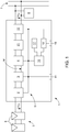
- the photovoltaic inverter 1 has at least one input DC-DC converter 2, an intermediate circuit 3 and an output DC-AC converter 4.
- An energy source 5 is connected to the input DC-DC converter 2, which are preferably formed from one or more solar modules 6 connected in parallel and / or in series with one another.
- the photovoltaic inverter 1 and the solar modules 6 are also referred to as a photovoltaic system or as a PV system.
- the output of the photovoltaic inverter 1 or the output DC-AC converter 4 can be connected to a supply network 7, such as a public or private AC voltage network or a multi-phase network, and / or with at least one electrical consumer 8, which represents a load , be connected.
- a consumer 8 is formed by a motor, refrigerator, radio device, etc.
- the consumer 8 can also represent a domestic supply.
- Such a photovoltaic inverter 1 preferably serves as a so-called grid-connected photovoltaic inverter 1, the energy management of which is optimized to feed as much energy into the supply network 7 as possible.
- the photovoltaic inverter 1 can also serve exclusively to supply loads 8. In this case one speaks of a so-called stand-alone inverter.
- the control device 10 of the photovoltaic inverter 1 is formed, for example, by a microprocessor, microcontroller or computer.
- a corresponding control of the individual components of the photovoltaic inverter 1, such as the input DC-DC converter 2 or the output DC-AC converter 4, in particular the switching elements arranged therein, can be carried out via the control device 10.
- the individual regulating or control sequences are stored in the control device 10 by means of corresponding software programs and / or data or characteristic curves.
- operating elements 11 can be connected to the control device 10 via the data bus 9, by means of which the user can configure the photovoltaic inverter 1 and / or display and set operating states or parameters (for example by means of light-emitting diodes).
- the Operating elements 11 are connected to the control device 10, for example via the data bus 9 or directly.
- Such operating elements 11 are arranged, for example, on a front of the photovoltaic inverter 1, so that operation from the outside is possible.
- the operating elements 11 can also be arranged directly on assemblies and / or modules within the photovoltaic inverter 1.
- auxiliary voltages are applied to the lines of the separation point 12 in a test mode via a control device, which can be formed by the existing control device 10 of the photovoltaic inverter 1, the switching contacts of the separation point 12 are actuated according to a switching pattern and various voltages at the output of the Separation point 12, measured at the separation point 12 and possibly at the input of the separation point 12, from which the individual voltages at the individual switching contacts of the separation point 12 can be back-calculated for each switching pattern and thus the correct functioning of all switching contacts can be determined.
- the voltages are measured against an intermediate circuit potential M of the intermediate circuit 3.
- devices for voltage measurement that are present in any case are preferably used.
- a device 18 serves for the intermediate storage and any averaging of the measured voltages over several periods.
- a warning device 19 can be used to issue a warning to a user or operator of the photovoltaic system in different ways, for example acoustically, visually or the like.
- a line filter 21 can be arranged, which prevents the transmission of impermissible high frequencies via the output AC voltage UAC into the supply network 7 or to the loads 8.
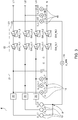
- Fig. 2 the structure of a separation point 12 for four lines Lx, preferably for a three-phase network with three phases L1, L2, L3 and a neutral conductor N is shown.
- each line Lx there are two switching contacts SW_Lx, 1 and SW_Lx, 2 in series.
- All lines Lx of the separation point 12 have inputs E_Lx, in the example shown the inputs E_Li of the phases Li and the input E_N of the neutral conductor N as well as outputs A_Lx, here in particular the outputs A_Li of the phases Li and the output A_N of the neutral conductor N.
- auxiliary voltages U_Lx are applied to the inputs E_Lx of the separation point 12 and, according to a switching pattern, the first switching contacts SW_Lx, 1 of the separation point 12 are alternately closed and the second switching contacts SW_Lx, 2 are opened and then the second switching contacts SW_Lx, 2 closed and the first switch contacts SW_Lx, 1 opened.
- voltages between the output A_Lx of each line Lx of the separation point 12 and the intermediate circuit potential M of the photovoltaic inverter 1 are measured.
- the functionality of each switch contact SW_Lx, j is finally derived from these measured voltages for each switching pattern of the switching contacts SW_Lx, j.
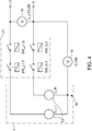
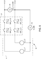
- Fig. 3 the structure of a separation point 12 between a photovoltaic inverter 1 and a supply network 7 or consumer 8 in a three-phase network with three phases L1, L2 and L3 and a neutral conductor using the method according to the invention for checking the separation point 12 is shown.
- auxiliary voltages U_Li are generated by corresponding devices 13, which are impressed between the input E_L1, E_L2, E_L3 of each phase L1, L2, L3 of the separation point 12 and the intermediate circuit potential M in the test mode for testing the switching contacts SW_Li, j and SW_N, j will.
- an auxiliary voltage U_L1 is supplied via a coupling capacitor C between the input E_N of the neutral conductor N of the separation point 12 and the intermediate circuit potential M impressed.
- the voltages U_L1, GD; U_L2, GD; U_L3, GD between the output A_L1; A_L2; A_L3 of each phase L1; L2; L3 of the separation point 12 and the output A_N of the neutral conductor N of the separation point 12 are measured.
- the voltage U_MN between the output A_N of the neutral conductor N of the isolating point 12 and the intermediate circuit potential M is detected via a device 16.
- At least one device 14 for measuring the voltage U_L1, LT between the input E_L1 of phase L1 and the input E_N of the neutral conductor N of the separation point 12 is also provided at the input of the separation point 12.
- the evaluation device 17 the calculation of the voltages at all switch contacts SW_Li, j and SW_N, j takes place to derive the functionality of each switch contact SW_Li, j and SW_N, j from the measured voltages for each switching pattern of the switch contacts SW_Li, j and SW_N, j. It is crucial that sufficient measurement information is available in order to be able to determine the voltages dropping across the switching contacts in order to be able to draw conclusions about their functionality.
- the test of the separation point 12 can be carried out with a single switching operation during the test mode. If the voltage difference at the switch contact is virtually zero, this is an indication that the switch contact is sticking, i.e. not working properly. If the voltage difference at a switch contact essentially corresponds to the impressed auxiliary voltage U_Li, U_N, the corresponding switch contact SW_Li, j or SW_N, j works.
- the following table shows the switching pattern for testing the switching contacts SW_Li, j; SW_N, j of the separation point 12 according to Fig. 3 .
- the total of eight switching contacts are activated according to a switching pattern, which contains two switching states 1 and 2, and the corresponding voltages are measured for each switching state 1 or 2, so that the differential voltages at all switching contacts SW_Lx, j are calculated back and thus sticking of the switching contacts SW_Lx , j can be determined.
Landscapes
- Physics & Mathematics (AREA)
- General Physics & Mathematics (AREA)
- Engineering & Computer Science (AREA)
- Power Engineering (AREA)
- Theoretical Computer Science (AREA)
- Chemical & Material Sciences (AREA)
- Combustion & Propulsion (AREA)
- Inverter Devices (AREA)
Claims (15)
- Procédé de contrôle d'un point de coupure (12) d'un onduleur photovoltaïque (1) comprenant un circuit intermédiaire (3), dans lequel le point de coupure (12) comporte au moins deux lignes (Lx) comprenant chacune deux contacts de commutation (SW_Lx,j) montés en série dans chaque ligne (Lx), les contacts de commutation (SW_Lx,j) sont actionnés en conséquence pour contrôler la fonctionnalité, caractérisé en ce que, dans un mode de contrôle, une tension auxiliaire (U_Lx) générée par l'onduleur photovoltaïque (1) est appliquée respectivement entre l'entrée (E_Lx) de chaque ligne (Lx) du point de coupure (12) et un potentiel de circuit intermédiaire (M), les premiers contacts de commutation (SW_Lx,1) du point de coupure (12) sont respectivement fermés et les seconds contacts de commutation (SW_Lx,2) sont respectivement ouverts puis les seconds contacts de commutation (SW_Lx,2) sont respectivement fermés et les premiers contacts de commutation (SW_Lx,1) sont respectivement ouverts selon un schéma de commutation en alternance et pour chaque schéma de commutation des contacts de commutation (SW_Lx,j), les tensions (U_Lx,GD ; U_MN) entre la sortie (A_Lx) de chaque ligne (Lx) du point de coupure (12) et le potentiel de circuit intermédiaire (M) sont mesurées et la fonctionnalité de chaque contact de commutation (SW_Lx,j) est déduite des tensions mesurées (U_Lx,GD ; U_MN) pour chaque schéma de commutation des contacts de commutation (SW_Lx,j).
- Procédé selon la revendication 1, caractérisé en ce que, en alternance, tous les premiers contacts de commutation (SW_Lx,1) du point de coupure (12) sont respectivement fermés simultanément et tous les seconds contacts de commutation (SW_Lx,2) sont respectivement ouverts puis tous les seconds contacts de commutation (SW_Lx,2) sont respectivement fermés simultanément et tous les premiers contacts de commutation (SW_Lx,1) sont respectivement ouverts.
- Procédé selon la revendication 1 ou 2, caractérisé en ce que, dans un onduleur photovoltaïque (1) pour un réseau d'alimentation triphasé (7) comprenant trois phases (L1, L2, L3) et un conducteur neutre (N), trois tensions auxiliaires (U_L1, U_L2, U_L3) générées par l'onduleur photovoltaïque (1) sont appliquées entre l'entrée (E_L1, E_L2, E_L3) de chaque phase (L1, L2, L3) du point de coupure (12) et le potentiel de circuit intermédiaire (M) et au moins une tension auxiliaire (U_L1) est appliquée entre l'entrée (E_N) du conducteur neutre (N) du point de coupure (12) et le potentiel de circuit intermédiaire (M) via un condensateur de couplage (C), et les tensions (U_L1,GD, U_L2,GD, U_L3,GD) entre la sortie (A_L1, A_L2, A_L3) de chaque phase (L1, L2, L3) et la sortie (A_N) du conducteur neutre (N) du point de coupure (12) et la tension (U_MN) entre la sortie (A_N) du conducteur neutre (N) du point de coupure (12) et le potentiel de circuit intermédiaire (M) ainsi qu'au moins une tension (U_Li,LT) entre l'entrée (E_Li) d'une phase (Li) et l'entrée (E_N) du conducteur neutre (N) du point de coupure (12) sont mesurées, et la fonctionnalité de chaque contact de commutation (SW_Li,j ; SW_N,j) est déduite des tensions mesurées (U_L1,GD, U_L2,GD, U_L3,GD, U_MN, U_Li,LT) pour chaque schéma de commutation des contacts de commutation (SW_Li,j ; SW_N,j).
- Procédé selon la revendication 1 ou 2, caractérisé en ce que, dans un onduleur photovoltaïque (1) pour un réseau d'alimentation monophasé (7) comprenant une phase (L1) et un conducteur neutre (N), deux tensions auxiliaires (U_L1, U_N) générées par l'onduleur photovoltaïque (1) sont appliquées entre l'entrée (E_L1) de la phase (L1) du point de coupure (12) et le potentiel de circuit intermédiaire (M) et entre l'entrée (E_N) du conducteur neutre (N) du point de coupure (12) et le potentiel de circuit intermédiaire (M), et la tension (U_L1N,GD) entre la sortie (A_L1) de la phase (L1) du point de coupure (12) et la sortie (A_N) du conducteur neutre (N) du point de coupure (12) et la tension (U_MN) entre la sortie (A_N) du conducteur neutre (N) du point de coupure (12) et le potentiel de circuit intermédiaire (M) sont mesurées, et la fonctionnalité de chaque contact de commutation (SW_Li,j ; SW_N,j) est déduite des tensions mesurées (U_L1N,GD ; U_MN) pour chaque schéma de commutation des contacts de commutation (SW_Li,j ; SW_N,j).
- Procédé selon la revendication 1 ou 2, caractérisé en ce que, dans un onduleur photovoltaïque (1) pour un réseau d'alimentation monophasé (7) comprenant deux phases (L1, L2), deux tensions auxiliaires (U_L1, U_L2) générées par l'onduleur photovoltaïque (1) sont appliquées entre l'entrée (E_L1, E_L2) de chaque phase (L1, L2) du point de coupure (12) et le potentiel de circuit intermédiaire (M), et la tension (U_L1L2,GD) entre les sorties (A_L1, A_L2) des phases (L1, L2) du point de coupure (12) et la tension (U_MN) entre la sortie (A_L2) d'une phase (L2) du point de coupure (12) et le potentiel de circuit intermédiaire (M) sont mesurées, et la fonctionnalité de chaque contact de commutation (SW_Li,j) est déduite des tensions mesurées (U_L1L2,GD ; U_MN) pour chaque schéma de commutation des contacts de commutation (SW_Li,j).
- Procédé selon l'une des revendications 1 à 5, caractérisé en ce que les tensions (U_Lx,LT ; U_Lx,GD ; U_MN) mesurées dans le mode de contrôle sont mesurées sur plusieurs périodes, de préférence 2 à 20, et la moyenne des valeurs mesurées est calculée.
- Procédé selon l'une des revendications 1 à 6, caractérisé en ce que, dans le mode de contrôle, le courant (I_Lx) dans chaque ligne (Lx) est mesuré et une limitation de courant est activée en cas de dépassement d'une valeur limite prédéterminée (I_Lx,g).
- Onduleur photovoltaïque (1) destiné à convertir une tension continue (UDC) en une tension alternative (UAC) pour alimenter en tension alternative (UAC) un réseau d'alimentation (7) et/ou pour alimenter des consommateurs (8), comprenant un convertisseur DC-DC d'entrée (2), un circuit intermédiaire (3), un convertisseur DC-AC de sortie (4) et un point de coupure (12) comportant au moins deux lignes (Lx) comprenant chacune deux contacts de commutation (SW_Lx,j) montés en série dans chaque ligne (Lx), caractérisé en ce que, dans un mode de contrôle permettant de contrôler les contacts de commutation (SW_Lx,j) du point de coupure (12), le convertisseur DC-AC de sortie (4) est conçu pour générer des tensions auxiliaires (U_Lx), à condition que les tensions auxiliaires (U_Lx) peuvent être appliquées entre l'entrée (E_Lx) de chaque ligne (Lx) du point de coupure (12) et un potentiel de circuit intermédiaire (M), un dispositif de commande (10) est conçu de telle sorte que les premiers contacts de commutation (SW_Lx,1) du point de coupure (12) sont respectivement fermés et les seconds contacts de commutation (SW_Lx,2) sont respectivement ouverts puis les seconds contacts de commutation (SW_Lx,2) sont respectivement fermés et tous les premiers contacts de commutation (SW_Lx,1) sont respectivement ouverts selon un schéma de commutation en alternance, et en ce que des dispositifs (14) de mesure des tensions (U_Lx,GD ; U_MN) sont prévus entre la sortie (A_Lx) de chaque ligne (Lx) du point de coupure (12) et le potentiel de circuit intermédiaire (M), et un dispositif d'analyse (17) est prévu pour déduire la fonctionnalité de chaque contact de commutation (SW_Lx,j) à partir des tensions mesurées (U_Lx,LT ; U_Lx,GD ; U_MN) pour chaque schéma de commutation des contacts de commutation (SW_Lx,j).
- Onduleur photovoltaïque (1) selon la revendication 8, caractérisé en ce que, pour un réseau d'alimentation triphasé (7) comprenant trois phases (L1, L2, L3) et un conducteur neutre (N), le convertisseur DC-AC de sortie (4) est conçu pour générer trois tensions auxiliaires (U_L1, U_L2, U_L3), à condition que les tensions auxiliaires (U_Li) peuvent être appliquées entre l'entrée (E_L1 ; E_L2 ; E_L3) de chaque phase (L1 ; L2 ; L3) du point de coupure (12) et le potentiel de circuit intermédiaire (M) et au moins une tension auxiliaire (U_L1) peut être appliquée entre l'entrée (E_N) du conducteur neutre (N) du point de coupure (12) et le potentiel de circuit intermédiaire (M) via un condensateur de couplage (C), et en ce que des dispositifs (14) de mesure des tensions (U_L1,GD ; U_L2,GD ; U_L3,GD) sont prévus entre la sortie (A_L1 ; A_L2 ; A_L3) de chaque phase (L1 ; L2 ; L3) du point de coupure (12) et la sortie (A_N) du conducteur neutre (N) du point de coupure (12), un dispositif (16) de mesure de la tension (U_MN) est prévu entre la sortie (A_N) du conducteur neutre (N) du point de coupure (12) et le potentiel de circuit intermédiaire (M) et au moins un dispositif (14) de mesure de la tension (U_Li,LT) est prévu entre l'entrée (E_Li) d'une phase (Li) et l'entrée (E_N) du conducteur neutre (N) du point de coupure (12), et en ce que le dispositif d'analyse (17) est conçu pour déduire la fonctionnalité de chaque contact de commutation (SW_Li,j ; SW_N,j) à partir des tensions mesurées (U_L1,GD ; U_L2,GD ; U_L3,GD ; U_MN ; U_L1,LT) pour chaque schéma de commutation des contacts de commutation (SW_Li,j ; SW_N,j).
- Onduleur photovoltaïque (1) selon la revendication 9, caractérisé en ce que le ou les condensateurs de couplage (C) sont formés par le condensateur (C) d'un filtre de ligne (21).
- Onduleur photovoltaïque (1) selon la revendication 8, caractérisé en ce que, pour un réseau d'alimentation monophasé (7) comprenant une phase (L1) et un conducteur neutre (N), le convertisseur DC-AC de sortie (4) est conçu pour générer deux tensions auxiliaires (U_L1, U_N), à condition que les tensions auxiliaires (U_L1, U_N) peuvent être appliquées entre l'entrée (E_L1) de la phase (L1) du point de coupure (12) et entre l'entrée (E_N) du conducteur neutre (N) du point de coupure (12) et le potentiel de circuit intermédiaire (M), et en ce qu'un dispositif (14) de mesure des tensions (U_L1N,GD) est prévu entre la sortie (A_L1) de la phase (L1) et la sortie (A_N) du conducteur neutre (N) du point de coupure (12) et un dispositif (16) de mesure de la tension (U_MN) est prévu entre la sortie (A_N) du conducteur neutre (N) du point de coupure (12) et le potentiel de circuit intermédiaire (M), et en ce que le dispositif d'analyse (17) est conçu pour déduire la fonctionnalité de chaque contact de commutation (SW_Li,j ; SW_N,j) à partir des tensions mesurées (U_L1N,GD ; U_MN) pour chaque schéma de commutation des contacts de commutation (SW_Li,j ; SW_N,j).
- Onduleur photovoltaïque (1) selon la revendication 8, caractérisé en ce que, pour un réseau d'alimentation monophasé (7) comprenant deux phases (L1, L2), le convertisseur DC-AC de sortie (4) est conçu pour générer deux tensions auxiliaires (U_L1, U_L2), à condition que les tensions auxiliaires (U_L1, U_L2) peuvent être appliquées entre les entrées (E_L1, E_L2) des phases (L1, L2) du point de coupure (12) et le potentiel de circuit intermédiaire (M), et en ce qu'un dispositif (15) de mesure de la tension (U_L1L2,GD) est prévu entre les sorties (A_L1, A_L2) des phases (L1, L2) du point de coupure (12) et un dispositif (16) de mesure de la tension (U_MN) est prévu entre la sortie (A_L2) d'une phase (L2) du point de coupure (12) et le potentiel de circuit intermédiaire (M), et en ce que le dispositif d'analyse (17) est conçu pour déduire la fonctionnalité de chaque contact de commutation (SW_Li,j ; SW_N,j) à partir des tensions mesurées (U_L1L2,GD ; U_MN) pour chaque schéma de commutation des contacts de commutation (SW_Li,j ; SW_N,j).
- Onduleur photovoltaïque (1) selon l'une des revendications 8 à 12, caractérisé en ce qu'un dispositif d'avertissement (19) est prévu pour émettre un message d'erreur en cas de détection d'un manque de fonctionnalité d'un contact de commutation (SW_Lx,j) du point de coupure (12).
- Onduleur photovoltaïque (1) selon l'une des revendications 8 à 13, caractérisé en ce que, dans le mode de contrôle, un dispositif (20) est prévu pour limiter le courant (I_Lx) dans chaque ligne (Lx).
- Onduleur photovoltaïque (1) selon l'une des revendications 8 à 14, caractérisé en ce que les premiers contacts de commutation (SW_Lx,1) respectifs de toutes les lignes (Lx) du point de coupure (12) sont formés par au moins un relais multipolaire (22) et les seconds contacts de commutation (SW_Lx,2) respectifs de toutes les lignes (Lx) du point de coupure (12) sont formés par au moins un autre relais multipolaire (23).
Priority Applications (1)
| Application Number | Priority Date | Filing Date | Title |
|---|---|---|---|
| PL19779492T PL3824524T3 (pl) | 2018-10-03 | 2019-10-03 | Sposób badania punktu odłączania falownika fotowoltaicznego oraz taki falownik fotowoltaiczny |
Applications Claiming Priority (2)
| Application Number | Priority Date | Filing Date | Title |
|---|---|---|---|
| EP18198509.4A EP3633817A1 (fr) | 2018-10-03 | 2018-10-03 | Procédé de vérification d'un point de séparation d'un onduleur photovoltaïque et un tel onduleur photovoltaïque |
| PCT/EP2019/076788 WO2020070234A1 (fr) | 2018-10-03 | 2019-10-03 | Procédé de vérification d'un point de coupure d'un onduleur photovoltaïque et onduleur photovoltaïque de ce type |
Publications (2)
| Publication Number | Publication Date |
|---|---|
| EP3824524A1 EP3824524A1 (fr) | 2021-05-26 |
| EP3824524B1 true EP3824524B1 (fr) | 2021-12-08 |
Family
ID=63762321
Family Applications (2)
| Application Number | Title | Priority Date | Filing Date |
|---|---|---|---|
| EP18198509.4A Withdrawn EP3633817A1 (fr) | 2018-10-03 | 2018-10-03 | Procédé de vérification d'un point de séparation d'un onduleur photovoltaïque et un tel onduleur photovoltaïque |
| EP19779492.8A Active EP3824524B1 (fr) | 2018-10-03 | 2019-10-03 | Procédé de vérification d'un point de séparation d'un onduleur photovoltaïque et un tel onduleur photovoltaïque |
Family Applications Before (1)
| Application Number | Title | Priority Date | Filing Date |
|---|---|---|---|
| EP18198509.4A Withdrawn EP3633817A1 (fr) | 2018-10-03 | 2018-10-03 | Procédé de vérification d'un point de séparation d'un onduleur photovoltaïque et un tel onduleur photovoltaïque |
Country Status (7)
| Country | Link |
|---|---|
| US (1) | US11125833B1 (fr) |
| EP (2) | EP3633817A1 (fr) |
| CN (1) | CN112771749B (fr) |
| AU (1) | AU2019352740B2 (fr) |
| ES (1) | ES2906373T3 (fr) |
| PL (1) | PL3824524T3 (fr) |
| WO (1) | WO2020070234A1 (fr) |
Families Citing this family (3)
| Publication number | Priority date | Publication date | Assignee | Title |
|---|---|---|---|---|
| EP3619783B1 (fr) * | 2017-05-05 | 2021-07-07 | Signify Holding B.V. | Système et procédé de conversion d'énergie |
| CN111864802B (zh) * | 2020-08-12 | 2022-05-24 | 阳光电源股份有限公司 | 光伏系统直流侧电力电子设备及其测试系统和控制方法 |
| EP4528956A1 (fr) * | 2023-09-25 | 2025-03-26 | Schneider Electric Industries Sas | Procédé de protection d'un micro-réseau contre une chute de tension ou une baisse de tension apparaissant dans un réseau principal connecté audit micro-réseau |
Family Cites Families (11)
| Publication number | Priority date | Publication date | Assignee | Title |
|---|---|---|---|---|
| JP3979278B2 (ja) * | 2002-11-29 | 2007-09-19 | 松下電工株式会社 | 系統連系インバータ装置 |
| EP2671315A2 (fr) * | 2010-06-04 | 2013-12-11 | ABB Inc. | Détection de contacts de commutation soudés dans un système de convertisseur de définition |
| CN102565691A (zh) * | 2011-12-14 | 2012-07-11 | 广州三晶电气有限公司 | 一种并网逆变器的继电器失效检测装置及方法 |
| DE102011122359A1 (de) * | 2011-12-23 | 2013-06-27 | Kostal Industrie Elektrik Gmbh | Schaltungsanordnung mit einem Wechselrichter und Verfahren zur Funktionsprüfung von elektromechanischen Schaltern |
| AT512983B1 (de) | 2012-06-13 | 2014-06-15 | Fronius Int Gmbh | Verfahren zur Prüfung einer Trennstelle eines Photovoltaik-Wechselrichters und Photovoltaik-Wechselrichter |
| AT513866B1 (de) * | 2013-02-14 | 2015-12-15 | Fronius Int Gmbh | Verfahren zur Prüfung einer Trennstelle eines Photovoltaik-Wechselrichters und Photovoltaik-Wechselrichter |
| DE102013104629A1 (de) * | 2013-05-06 | 2014-11-06 | Refusol Gmbh | Energieerzeugungseinrichtung mit funktionssicherer Potentialtrennung |
| DE102013110240B4 (de) * | 2013-09-17 | 2017-09-07 | Sma Solar Technology Ag | Schaltungsanordnung für einen Photovoltaikwechselrichter zur Ausschaltentlastung mit Kurzschlussschaltern und Verwendungen der Schaltungsanordnung |
| DE102013113000A1 (de) * | 2013-11-25 | 2015-05-28 | Sma Solar Technology Ag | Verfahren zum Betreiben eines Wechselrichters und Wechselrichter mit einem Schalter zwischen einem Mittelpunkt eines Gleichspannungszwischenkreises und einem Anschluss für einen Nullleiter eines Wechselstromnetzes |
| CN203981841U (zh) | 2014-07-04 | 2014-12-03 | 广东易事特电源股份有限公司 | 单相光伏并网逆变器自动断路装置 |
| EP3252937A1 (fr) * | 2016-06-03 | 2017-12-06 | Fronius International GmbH | Onduleur et procédé de fonctionnement d'un onduleur |
-
2018
- 2018-10-03 EP EP18198509.4A patent/EP3633817A1/fr not_active Withdrawn
-
2019
- 2019-10-03 PL PL19779492T patent/PL3824524T3/pl unknown
- 2019-10-03 CN CN201980059047.6A patent/CN112771749B/zh active Active
- 2019-10-03 AU AU2019352740A patent/AU2019352740B2/en active Active
- 2019-10-03 ES ES19779492T patent/ES2906373T3/es active Active
- 2019-10-03 US US17/274,245 patent/US11125833B1/en active Active
- 2019-10-03 WO PCT/EP2019/076788 patent/WO2020070234A1/fr not_active Ceased
- 2019-10-03 EP EP19779492.8A patent/EP3824524B1/fr active Active
Also Published As
| Publication number | Publication date |
|---|---|
| BR112021003879A2 (pt) | 2021-05-18 |
| EP3633817A1 (fr) | 2020-04-08 |
| AU2019352740B2 (en) | 2021-09-23 |
| US20210311130A1 (en) | 2021-10-07 |
| WO2020070234A1 (fr) | 2020-04-09 |
| AU2019352740A1 (en) | 2021-04-01 |
| EP3824524A1 (fr) | 2021-05-26 |
| US11125833B1 (en) | 2021-09-21 |
| ES2906373T3 (es) | 2022-04-18 |
| PL3824524T3 (pl) | 2022-04-19 |
| CN112771749B (zh) | 2021-11-09 |
| CN112771749A (zh) | 2021-05-07 |
Similar Documents
| Publication | Publication Date | Title |
|---|---|---|
| EP3625863B1 (fr) | Localisation d'un défaut de terre dans un réseau it | |
| EP3391519B1 (fr) | Onduleur et procede de fonctionnement d'un onduleur | |
| EP3059828B1 (fr) | Dispositif et procede de detection de courant differentiel | |
| DE102015114452B4 (de) | Verfahren zum Betrieb eines Wechselrichters und Wechselrichter | |
| DE102012104560B4 (de) | Erkennung der Stringkonfiguration für einen Multistring-Wechselrichter | |
| DE102011054002A1 (de) | Dezentrale Energieerzeugungsanlage mit Einrichtung und Verfahren zur Inselnetzerkennung | |
| EP2994767A1 (fr) | Dispositif de production d'énergie à séparation de potentiel fiable | |
| EP3254351B9 (fr) | Contrôle de filtre | |
| EP3824524B1 (fr) | Procédé de vérification d'un point de séparation d'un onduleur photovoltaïque et un tel onduleur photovoltaïque | |
| EP2837012B1 (fr) | Procédé de vérification d'un point de coupure d'un onduleur photovoltaïque et onduleur photovoltaïque | |
| DE102014202426B4 (de) | Verfahren zur Prüfung einer Trennstelle eines Photovoltaik-Wechselrichters und Photovoltaik-Wechselrichter | |
| EP3625866A1 (fr) | Alimentation de courant sans interruption | |
| EP3696927A1 (fr) | Dispositif et procédé de surveillance d'une pluralité de départs de courant dans un réseau électrique | |
| EP2709226B1 (fr) | Agencement de circuit ainsi que convertisseur de niveau et circuit comparateur pour l'agencement de circuit | |
| EP4252014B1 (fr) | Dispositif de surveillance destiné au fonctionnement de réseau de substitution | |
| EP3629041A1 (fr) | Procédé et dispositif de mise en uvre d'un essai de coupure sur un onduleur | |
| EP2572921A1 (fr) | Surveillance d'un circuit |
Legal Events
| Date | Code | Title | Description |
|---|---|---|---|
| STAA | Information on the status of an ep patent application or granted ep patent |
Free format text: STATUS: UNKNOWN |
|
| STAA | Information on the status of an ep patent application or granted ep patent |
Free format text: STATUS: THE INTERNATIONAL PUBLICATION HAS BEEN MADE |
|
| PUAI | Public reference made under article 153(3) epc to a published international application that has entered the european phase |
Free format text: ORIGINAL CODE: 0009012 |
|
| STAA | Information on the status of an ep patent application or granted ep patent |
Free format text: STATUS: REQUEST FOR EXAMINATION WAS MADE |
|
| 17P | Request for examination filed |
Effective date: 20210216 |
|
| AK | Designated contracting states |
Kind code of ref document: A1 Designated state(s): AL AT BE BG CH CY CZ DE DK EE ES FI FR GB GR HR HU IE IS IT LI LT LU LV MC MK MT NL NO PL PT RO RS SE SI SK SM TR |
|
| GRAP | Despatch of communication of intention to grant a patent |
Free format text: ORIGINAL CODE: EPIDOSNIGR1 |
|
| STAA | Information on the status of an ep patent application or granted ep patent |
Free format text: STATUS: GRANT OF PATENT IS INTENDED |
|
| INTG | Intention to grant announced |
Effective date: 20210624 |
|
| GRAS | Grant fee paid |
Free format text: ORIGINAL CODE: EPIDOSNIGR3 |
|
| GRAA | (expected) grant |
Free format text: ORIGINAL CODE: 0009210 |
|
| STAA | Information on the status of an ep patent application or granted ep patent |
Free format text: STATUS: THE PATENT HAS BEEN GRANTED |
|
| DAV | Request for validation of the european patent (deleted) | ||
| DAX | Request for extension of the european patent (deleted) | ||
| AK | Designated contracting states |
Kind code of ref document: B1 Designated state(s): AL AT BE BG CH CY CZ DE DK EE ES FI FR GB GR HR HU IE IS IT LI LT LU LV MC MK MT NL NO PL PT RO RS SE SI SK SM TR |
|
| REG | Reference to a national code |
Ref country code: GB Ref legal event code: FG4D Free format text: NOT ENGLISH |
|
| REG | Reference to a national code |
Ref country code: AT Ref legal event code: REF Ref document number: 1454473 Country of ref document: AT Kind code of ref document: T Effective date: 20211215 Ref country code: CH Ref legal event code: EP |
|
| REG | Reference to a national code |
Ref country code: DE Ref legal event code: R096 Ref document number: 502019002972 Country of ref document: DE |
|
| REG | Reference to a national code |
Ref country code: IE Ref legal event code: FG4D Free format text: LANGUAGE OF EP DOCUMENT: GERMAN |
|
| REG | Reference to a national code |
Ref country code: LT Ref legal event code: MG9D |
|
| REG | Reference to a national code |
Ref country code: NL Ref legal event code: MP Effective date: 20211208 |
|
| REG | Reference to a national code |
Ref country code: ES Ref legal event code: FG2A Ref document number: 2906373 Country of ref document: ES Kind code of ref document: T3 Effective date: 20220418 |
|
| PG25 | Lapsed in a contracting state [announced via postgrant information from national office to epo] |
Ref country code: RS Free format text: LAPSE BECAUSE OF FAILURE TO SUBMIT A TRANSLATION OF THE DESCRIPTION OR TO PAY THE FEE WITHIN THE PRESCRIBED TIME-LIMIT Effective date: 20211208 Ref country code: LT Free format text: LAPSE BECAUSE OF FAILURE TO SUBMIT A TRANSLATION OF THE DESCRIPTION OR TO PAY THE FEE WITHIN THE PRESCRIBED TIME-LIMIT Effective date: 20211208 Ref country code: FI Free format text: LAPSE BECAUSE OF FAILURE TO SUBMIT A TRANSLATION OF THE DESCRIPTION OR TO PAY THE FEE WITHIN THE PRESCRIBED TIME-LIMIT Effective date: 20211208 Ref country code: BG Free format text: LAPSE BECAUSE OF FAILURE TO SUBMIT A TRANSLATION OF THE DESCRIPTION OR TO PAY THE FEE WITHIN THE PRESCRIBED TIME-LIMIT Effective date: 20220308 |
|
| PG25 | Lapsed in a contracting state [announced via postgrant information from national office to epo] |
Ref country code: SE Free format text: LAPSE BECAUSE OF FAILURE TO SUBMIT A TRANSLATION OF THE DESCRIPTION OR TO PAY THE FEE WITHIN THE PRESCRIBED TIME-LIMIT Effective date: 20211208 Ref country code: NO Free format text: LAPSE BECAUSE OF FAILURE TO SUBMIT A TRANSLATION OF THE DESCRIPTION OR TO PAY THE FEE WITHIN THE PRESCRIBED TIME-LIMIT Effective date: 20220308 Ref country code: LV Free format text: LAPSE BECAUSE OF FAILURE TO SUBMIT A TRANSLATION OF THE DESCRIPTION OR TO PAY THE FEE WITHIN THE PRESCRIBED TIME-LIMIT Effective date: 20211208 Ref country code: HR Free format text: LAPSE BECAUSE OF FAILURE TO SUBMIT A TRANSLATION OF THE DESCRIPTION OR TO PAY THE FEE WITHIN THE PRESCRIBED TIME-LIMIT Effective date: 20211208 Ref country code: GR Free format text: LAPSE BECAUSE OF FAILURE TO SUBMIT A TRANSLATION OF THE DESCRIPTION OR TO PAY THE FEE WITHIN THE PRESCRIBED TIME-LIMIT Effective date: 20220309 |
|
| PG25 | Lapsed in a contracting state [announced via postgrant information from national office to epo] |
Ref country code: NL Free format text: LAPSE BECAUSE OF FAILURE TO SUBMIT A TRANSLATION OF THE DESCRIPTION OR TO PAY THE FEE WITHIN THE PRESCRIBED TIME-LIMIT Effective date: 20211208 |
|
| PG25 | Lapsed in a contracting state [announced via postgrant information from national office to epo] |
Ref country code: SM Free format text: LAPSE BECAUSE OF FAILURE TO SUBMIT A TRANSLATION OF THE DESCRIPTION OR TO PAY THE FEE WITHIN THE PRESCRIBED TIME-LIMIT Effective date: 20211208 Ref country code: SK Free format text: LAPSE BECAUSE OF FAILURE TO SUBMIT A TRANSLATION OF THE DESCRIPTION OR TO PAY THE FEE WITHIN THE PRESCRIBED TIME-LIMIT Effective date: 20211208 Ref country code: RO Free format text: LAPSE BECAUSE OF FAILURE TO SUBMIT A TRANSLATION OF THE DESCRIPTION OR TO PAY THE FEE WITHIN THE PRESCRIBED TIME-LIMIT Effective date: 20211208 Ref country code: PT Free format text: LAPSE BECAUSE OF FAILURE TO SUBMIT A TRANSLATION OF THE DESCRIPTION OR TO PAY THE FEE WITHIN THE PRESCRIBED TIME-LIMIT Effective date: 20220408 Ref country code: EE Free format text: LAPSE BECAUSE OF FAILURE TO SUBMIT A TRANSLATION OF THE DESCRIPTION OR TO PAY THE FEE WITHIN THE PRESCRIBED TIME-LIMIT Effective date: 20211208 Ref country code: CZ Free format text: LAPSE BECAUSE OF FAILURE TO SUBMIT A TRANSLATION OF THE DESCRIPTION OR TO PAY THE FEE WITHIN THE PRESCRIBED TIME-LIMIT Effective date: 20211208 |
|
| REG | Reference to a national code |
Ref country code: DE Ref legal event code: R097 Ref document number: 502019002972 Country of ref document: DE |
|
| PG25 | Lapsed in a contracting state [announced via postgrant information from national office to epo] |
Ref country code: IS Free format text: LAPSE BECAUSE OF FAILURE TO SUBMIT A TRANSLATION OF THE DESCRIPTION OR TO PAY THE FEE WITHIN THE PRESCRIBED TIME-LIMIT Effective date: 20220408 |
|
| PLBE | No opposition filed within time limit |
Free format text: ORIGINAL CODE: 0009261 |
|
| STAA | Information on the status of an ep patent application or granted ep patent |
Free format text: STATUS: NO OPPOSITION FILED WITHIN TIME LIMIT |
|
| PG25 | Lapsed in a contracting state [announced via postgrant information from national office to epo] |
Ref country code: DK Free format text: LAPSE BECAUSE OF FAILURE TO SUBMIT A TRANSLATION OF THE DESCRIPTION OR TO PAY THE FEE WITHIN THE PRESCRIBED TIME-LIMIT Effective date: 20211208 Ref country code: AL Free format text: LAPSE BECAUSE OF FAILURE TO SUBMIT A TRANSLATION OF THE DESCRIPTION OR TO PAY THE FEE WITHIN THE PRESCRIBED TIME-LIMIT Effective date: 20211208 |
|
| 26N | No opposition filed |
Effective date: 20220909 |
|
| PG25 | Lapsed in a contracting state [announced via postgrant information from national office to epo] |
Ref country code: MC Free format text: LAPSE BECAUSE OF FAILURE TO SUBMIT A TRANSLATION OF THE DESCRIPTION OR TO PAY THE FEE WITHIN THE PRESCRIBED TIME-LIMIT Effective date: 20211208 |
|
| REG | Reference to a national code |
Ref country code: CH Ref legal event code: PL |
|
| P01 | Opt-out of the competence of the unified patent court (upc) registered |
Effective date: 20230516 |
|
| REG | Reference to a national code |
Ref country code: BE Ref legal event code: MM Effective date: 20221031 |
|
| PG25 | Lapsed in a contracting state [announced via postgrant information from national office to epo] |
Ref country code: LU Free format text: LAPSE BECAUSE OF NON-PAYMENT OF DUE FEES Effective date: 20221003 |
|
| PG25 | Lapsed in a contracting state [announced via postgrant information from national office to epo] |
Ref country code: LI Free format text: LAPSE BECAUSE OF NON-PAYMENT OF DUE FEES Effective date: 20221031 Ref country code: CH Free format text: LAPSE BECAUSE OF NON-PAYMENT OF DUE FEES Effective date: 20221031 |
|
| PG25 | Lapsed in a contracting state [announced via postgrant information from national office to epo] |
Ref country code: BE Free format text: LAPSE BECAUSE OF NON-PAYMENT OF DUE FEES Effective date: 20221031 |
|
| PG25 | Lapsed in a contracting state [announced via postgrant information from national office to epo] |
Ref country code: IE Free format text: LAPSE BECAUSE OF NON-PAYMENT OF DUE FEES Effective date: 20221003 |
|
| REG | Reference to a national code |
Ref country code: DE Ref legal event code: R082 Ref document number: 502019002972 Country of ref document: DE Representative=s name: BRATOVIC, NINO, DR. RER. NAT., DE |
|
| PG25 | Lapsed in a contracting state [announced via postgrant information from national office to epo] |
Ref country code: CY Free format text: LAPSE BECAUSE OF FAILURE TO SUBMIT A TRANSLATION OF THE DESCRIPTION OR TO PAY THE FEE WITHIN THE PRESCRIBED TIME-LIMIT Effective date: 20211208 |
|
| PG25 | Lapsed in a contracting state [announced via postgrant information from national office to epo] |
Ref country code: MK Free format text: LAPSE BECAUSE OF FAILURE TO SUBMIT A TRANSLATION OF THE DESCRIPTION OR TO PAY THE FEE WITHIN THE PRESCRIBED TIME-LIMIT Effective date: 20211208 Ref country code: HU Free format text: LAPSE BECAUSE OF FAILURE TO SUBMIT A TRANSLATION OF THE DESCRIPTION OR TO PAY THE FEE WITHIN THE PRESCRIBED TIME-LIMIT; INVALID AB INITIO Effective date: 20191003 |
|
| GBPC | Gb: european patent ceased through non-payment of renewal fee |
Effective date: 20231003 |
|
| PG25 | Lapsed in a contracting state [announced via postgrant information from national office to epo] |
Ref country code: TR Free format text: LAPSE BECAUSE OF FAILURE TO SUBMIT A TRANSLATION OF THE DESCRIPTION OR TO PAY THE FEE WITHIN THE PRESCRIBED TIME-LIMIT Effective date: 20211208 |
|
| PG25 | Lapsed in a contracting state [announced via postgrant information from national office to epo] |
Ref country code: GB Free format text: LAPSE BECAUSE OF NON-PAYMENT OF DUE FEES Effective date: 20231003 |
|
| PG25 | Lapsed in a contracting state [announced via postgrant information from national office to epo] |
Ref country code: GB Free format text: LAPSE BECAUSE OF NON-PAYMENT OF DUE FEES Effective date: 20231003 |
|
| PG25 | Lapsed in a contracting state [announced via postgrant information from national office to epo] |
Ref country code: MT Free format text: LAPSE BECAUSE OF FAILURE TO SUBMIT A TRANSLATION OF THE DESCRIPTION OR TO PAY THE FEE WITHIN THE PRESCRIBED TIME-LIMIT Effective date: 20211208 |
|
| PGFP | Annual fee paid to national office [announced via postgrant information from national office to epo] |
Ref country code: PL Payment date: 20250922 Year of fee payment: 7 |
|
| PGFP | Annual fee paid to national office [announced via postgrant information from national office to epo] |
Ref country code: DE Payment date: 20251028 Year of fee payment: 7 |
|
| PGFP | Annual fee paid to national office [announced via postgrant information from national office to epo] |
Ref country code: AT Payment date: 20251017 Year of fee payment: 7 |
|
| PGFP | Annual fee paid to national office [announced via postgrant information from national office to epo] |
Ref country code: IT Payment date: 20251024 Year of fee payment: 7 |
|
| PGFP | Annual fee paid to national office [announced via postgrant information from national office to epo] |
Ref country code: FR Payment date: 20251027 Year of fee payment: 7 |
|
| PGFP | Annual fee paid to national office [announced via postgrant information from national office to epo] |
Ref country code: ES Payment date: 20251118 Year of fee payment: 7 |
|
| PG25 | Lapsed in a contracting state [announced via postgrant information from national office to epo] |
Ref country code: SI Free format text: LAPSE BECAUSE OF FAILURE TO SUBMIT A TRANSLATION OF THE DESCRIPTION OR TO PAY THE FEE WITHIN THE PRESCRIBED TIME-LIMIT Effective date: 20211208 |