EP2572921A1 - Surveillance d'un circuit - Google Patents
Surveillance d'un circuit Download PDFInfo
- Publication number
- EP2572921A1 EP2572921A1 EP11182737A EP11182737A EP2572921A1 EP 2572921 A1 EP2572921 A1 EP 2572921A1 EP 11182737 A EP11182737 A EP 11182737A EP 11182737 A EP11182737 A EP 11182737A EP 2572921 A1 EP2572921 A1 EP 2572921A1
- Authority
- EP
- European Patent Office
- Prior art keywords
- electrical
- battery
- circuit
- power flow
- impedance
- Prior art date
- Legal status (The legal status is an assumption and is not a legal conclusion. Google has not performed a legal analysis and makes no representation as to the accuracy of the status listed.)
- Withdrawn
Links
- 238000012544 monitoring process Methods 0.000 title claims description 7
- 238000000034 method Methods 0.000 claims abstract description 38
- 239000003990 capacitor Substances 0.000 claims abstract description 31
- 230000004044 response Effects 0.000 claims description 13
- 125000004122 cyclic group Chemical group 0.000 claims description 6
- 238000007599 discharging Methods 0.000 claims description 2
- 238000012360 testing method Methods 0.000 claims description 2
- 230000003213 activating effect Effects 0.000 claims 1
- 238000011161 development Methods 0.000 description 7
- 230000018109 developmental process Effects 0.000 description 7
- 230000008569 process Effects 0.000 description 3
- 230000008859 change Effects 0.000 description 2
- 238000013461 design Methods 0.000 description 2
- 230000006870 function Effects 0.000 description 2
- 230000001419 dependent effect Effects 0.000 description 1
- 238000001514 detection method Methods 0.000 description 1
- 230000000694 effects Effects 0.000 description 1
- 238000004146 energy storage Methods 0.000 description 1
- 230000020169 heat generation Effects 0.000 description 1
- 230000002452 interceptive effect Effects 0.000 description 1
- 238000012423 maintenance Methods 0.000 description 1
- 238000004519 manufacturing process Methods 0.000 description 1
- 238000012986 modification Methods 0.000 description 1
- 230000004048 modification Effects 0.000 description 1
- 238000012549 training Methods 0.000 description 1
- 230000009466 transformation Effects 0.000 description 1
- 238000000844 transformation Methods 0.000 description 1
- 238000012795 verification Methods 0.000 description 1
Images
Classifications
-
- B—PERFORMING OPERATIONS; TRANSPORTING
- B60—VEHICLES IN GENERAL
- B60L—PROPULSION OF ELECTRICALLY-PROPELLED VEHICLES; SUPPLYING ELECTRIC POWER FOR AUXILIARY EQUIPMENT OF ELECTRICALLY-PROPELLED VEHICLES; ELECTRODYNAMIC BRAKE SYSTEMS FOR VEHICLES IN GENERAL; MAGNETIC SUSPENSION OR LEVITATION FOR VEHICLES; MONITORING OPERATING VARIABLES OF ELECTRICALLY-PROPELLED VEHICLES; ELECTRIC SAFETY DEVICES FOR ELECTRICALLY-PROPELLED VEHICLES
- B60L15/00—Methods, circuits, or devices for controlling the traction-motor speed of electrically-propelled vehicles
- B60L15/007—Physical arrangements or structures of drive train converters specially adapted for the propulsion motors of electric vehicles
-
- B—PERFORMING OPERATIONS; TRANSPORTING
- B60—VEHICLES IN GENERAL
- B60L—PROPULSION OF ELECTRICALLY-PROPELLED VEHICLES; SUPPLYING ELECTRIC POWER FOR AUXILIARY EQUIPMENT OF ELECTRICALLY-PROPELLED VEHICLES; ELECTRODYNAMIC BRAKE SYSTEMS FOR VEHICLES IN GENERAL; MAGNETIC SUSPENSION OR LEVITATION FOR VEHICLES; MONITORING OPERATING VARIABLES OF ELECTRICALLY-PROPELLED VEHICLES; ELECTRIC SAFETY DEVICES FOR ELECTRICALLY-PROPELLED VEHICLES
- B60L3/00—Electric devices on electrically-propelled vehicles for safety purposes; Monitoring operating variables, e.g. speed, deceleration or energy consumption
- B60L3/0023—Detecting, eliminating, remedying or compensating for drive train abnormalities, e.g. failures within the drive train
- B60L3/0069—Detecting, eliminating, remedying or compensating for drive train abnormalities, e.g. failures within the drive train relating to the isolation, e.g. ground fault or leak current
-
- B—PERFORMING OPERATIONS; TRANSPORTING
- B60—VEHICLES IN GENERAL
- B60L—PROPULSION OF ELECTRICALLY-PROPELLED VEHICLES; SUPPLYING ELECTRIC POWER FOR AUXILIARY EQUIPMENT OF ELECTRICALLY-PROPELLED VEHICLES; ELECTRODYNAMIC BRAKE SYSTEMS FOR VEHICLES IN GENERAL; MAGNETIC SUSPENSION OR LEVITATION FOR VEHICLES; MONITORING OPERATING VARIABLES OF ELECTRICALLY-PROPELLED VEHICLES; ELECTRIC SAFETY DEVICES FOR ELECTRICALLY-PROPELLED VEHICLES
- B60L50/00—Electric propulsion with power supplied within the vehicle
- B60L50/50—Electric propulsion with power supplied within the vehicle using propulsion power supplied by batteries or fuel cells
- B60L50/51—Electric propulsion with power supplied within the vehicle using propulsion power supplied by batteries or fuel cells characterised by AC-motors
-
- G—PHYSICS
- G01—MEASURING; TESTING
- G01R—MEASURING ELECTRIC VARIABLES; MEASURING MAGNETIC VARIABLES
- G01R31/00—Arrangements for testing electric properties; Arrangements for locating electric faults; Arrangements for electrical testing characterised by what is being tested not provided for elsewhere
- G01R31/005—Testing of electric installations on transport means
- G01R31/006—Testing of electric installations on transport means on road vehicles, e.g. automobiles or trucks
-
- G—PHYSICS
- G01—MEASURING; TESTING
- G01R—MEASURING ELECTRIC VARIABLES; MEASURING MAGNETIC VARIABLES
- G01R31/00—Arrangements for testing electric properties; Arrangements for locating electric faults; Arrangements for electrical testing characterised by what is being tested not provided for elsewhere
- G01R31/50—Testing of electric apparatus, lines, cables or components for short-circuits, continuity, leakage current or incorrect line connections
- G01R31/54—Testing for continuity
-
- Y—GENERAL TAGGING OF NEW TECHNOLOGICAL DEVELOPMENTS; GENERAL TAGGING OF CROSS-SECTIONAL TECHNOLOGIES SPANNING OVER SEVERAL SECTIONS OF THE IPC; TECHNICAL SUBJECTS COVERED BY FORMER USPC CROSS-REFERENCE ART COLLECTIONS [XRACs] AND DIGESTS
- Y02—TECHNOLOGIES OR APPLICATIONS FOR MITIGATION OR ADAPTATION AGAINST CLIMATE CHANGE
- Y02T—CLIMATE CHANGE MITIGATION TECHNOLOGIES RELATED TO TRANSPORTATION
- Y02T10/00—Road transport of goods or passengers
- Y02T10/60—Other road transportation technologies with climate change mitigation effect
- Y02T10/64—Electric machine technologies in electromobility
-
- Y—GENERAL TAGGING OF NEW TECHNOLOGICAL DEVELOPMENTS; GENERAL TAGGING OF CROSS-SECTIONAL TECHNOLOGIES SPANNING OVER SEVERAL SECTIONS OF THE IPC; TECHNICAL SUBJECTS COVERED BY FORMER USPC CROSS-REFERENCE ART COLLECTIONS [XRACs] AND DIGESTS
- Y02—TECHNOLOGIES OR APPLICATIONS FOR MITIGATION OR ADAPTATION AGAINST CLIMATE CHANGE
- Y02T—CLIMATE CHANGE MITIGATION TECHNOLOGIES RELATED TO TRANSPORTATION
- Y02T10/00—Road transport of goods or passengers
- Y02T10/60—Other road transportation technologies with climate change mitigation effect
- Y02T10/70—Energy storage systems for electromobility, e.g. batteries
Definitions
- the invention relates to a method for monitoring a circuit of a battery and an electrical consumer connected to the battery and a device for carrying out the method.
- circuits that are housed in non-stationary, movable devices, such as a vehicle usually electrical consumers are powered by a battery with electrical energy.
- the electrical load and the battery are installed in a circuit.
- the power circuit of the battery and the electrical load can be closed by an unintentional contact, for example by persons via a ground fault.
- life-threatening leakage currents can flow through the touching person in the form of body currents.
- the intermediate circuit such as an intermediate circuit capacitor, is also contained in the power-conducting circuit between the electrical load and the battery, these must be discharged for safety purposes, for example for the purpose of repairing or eliminating errors after interrupting the power-carrying circuit, so that the maintenance personnel are not dangerous when the temporary storage device is touched Body currents are made to flow.
- the power-conducting circuit is made using so-called pilot lines or high-voltage interlocks supervised. This is an electrically redundant circuit, which is connected in parallel with the power-carrying circuit. If the redundant circuit is open, then it can be assumed that the power-conducting circuit is open.
- the invention proposes to find out, based on a variation of the power flow through the circuit of the battery and the electrical load and a reaction of the circuit with the battery and the electrical load, whether the circuit is interrupted.
- the proposal is based on the finding that changes in the power flow must lead to plausible responses in the circuit when the power circuit is closed. In other words, a defined change in the power flow between the battery and the electrical load must lead to a verifiable reaction of the circuit when the circuit between the battery and the electrical load is closed.
- the consideration of the invention is therefore to define a defined change in the power flow and to first determine the verifiable reaction, for example by calculation. Then, according to the invention, it can be checked in the circuit whether the testable reaction actually occurs.
- the invention therefore provides a method of monitoring a circuit having a battery and an electrical consumer connected to the battery.
- the specified method includes varying an electrical power flow between the battery and the electrical load, detecting a response of the circuit to the variation and determining an error if the sensed response deviates from a predetermined response.
- any electrical and physical quantities in the circuit that depend on the power flow between the battery and the electrical load can be used. These may be, for example, the values of the total resistance or the operating point of the circuit. However, other physical quantities, such as heat generation or interference emission, can also be used to monitor the circuit between the battery and the electrical consumer according to the invention.
- interruptions of the circuit between the battery and the electrical load can be determined without an additional redundant circuit, such as a pilot line or a high-voltage interlock is necessary.
- additional redundant circuit such as a pilot line or a high-voltage interlock is necessary.
- the disclosed method may also monitor the circuitry of the circuit with respect to a much wider variety of sources of error, since the response of the circuit to a variation in power flow will deviate from the predetermined response not only in the event of a circuit break, but also in the event of other errors.
- faults can be, for example, shorts in the circuit but also component drift effects, which, for example, can occur at the battery or the electrical load due to age.
- the variation of the electrical power flow takes place with a specific pattern.
- This pattern is for example by means of a signal generator not only easier to produce, the pattern can also be easily adapted to the conditions of the circuit, so that the circuit is not transferred by the variation of the power flow, for example, in critical operating conditions that can damage the circuit or even destroy.
- the specified method comprises the step of detecting an electrical variable describing the circuit and searching for the pattern in the detected electrical quantity.
- the development is based on the idea that in the case of interruptions and short circuits in the circuit between the battery and the electrical load no electrical power can be transmitted. Consequently, a variation of the power flow also leads to no reaction of the circuit.
- the pattern can therefore only be found in the response of the circuit if the circuit is free of open circuits and short circuits. In this way, the verification of whether the measured reaction deviates from the predetermined reaction can be carried out in a particularly simple manner, since the predetermined reaction is already known by the pattern used and does not have to be defined first.
- the pattern is a cyclic variation of the electric power flow.
- the cyclic variation may take any form, such as a sine or a pseudo-random form.
- the specified method comprises the step of correlating the electrical variable with the cyclic electrical power flow for searching the pattern. Correlation efficiently filters interfering signals such as noise in the detected response become.
- the method of this development in a simple manner with known circuit elements, such as a lock-in amplifier can be implemented, which are available inexpensively and proven.
- the specified method comprises the step of driving a switch of an electrical converter for varying the electrical power flow, wherein the electrical converter is provided for converting an output from the battery and transmitted to the electrical load electrical power.
- the electrical converter is present in numerous applications, for example in the form of an inverter. Its control is usually purely electronic, for example, by a running on a control computer control software. This control software can be shared by suitable modifications for the practical implementation of the specified method, so that no additional mechanical or other structural design measures to the circuit are necessary to realize the invention.
- the specified design also makes it possible to equip conventional, already existing circuits with an electrical converter but without pilot lines or high-voltage interlocks with a safety function which monitors the circuit for interruptions or other faults, such as short circuits.
- the specified method comprises the step of discharging a capacitor based on the error message, the capacity being provided for temporarily storing electrical energy transmitted between the battery and the electrical load.
- the energy storage capacity can pose a security risk especially in the case of interruptions in the circuit, as it leads to dangerous voltages that can be discharged as mentioned above in contact, for example, by people on this. By the specified procedure This security risk can not only be recognized but also effectively minimized.
- the specified method includes the step of determining the error when a fluctuation of the detected electrical quantity falls outside a predetermined range for the fluctuation.
- the predetermined range for the fluctuation can be predetermined, for example, by a few threshold values, so that the error determination can be carried out directly with a measured variable without further signal transformations.
- the predetermined range for the fluctuation comprises a value of the electrical variable at which the battery feeds an electrical test consumer, in particular a DC link capacitor, between the battery and the electrical load with electrical energy.
- the DC link capacitor is supplied by the battery with electrical energy.
- the DC link capacitor takes over the electrical power supply of the load, which leads to strong fluctuations in the voltage at the DC link capacitor.
- the voltage at the DC link capacitor no longer fluctuates at all, since even the DC link capacitor can no longer transmit any electrical power in the event of a short circuit. In this way, an interruption can not only be detected but also distinguished from a short circuit.
- the specified method includes the step of detecting an impedance of the circuit and determining the error if the impedance falls outside a predetermined range.
- the electrical variables necessary for the impedance calculation can be detected at any point in the circuit. This is advantageous in particular for the case that an already mentioned electrical converter is used, since its measured value detection can be used to implement the method without the circuit must be structurally changed.
- the predetermined range includes an impedance having a value of impedance from an interconnection of the battery and the electrical load.
- the impedance of the predetermined range can thus characterize the error-free case, wherein the range can be arbitrarily subject to tolerances in order to avoid an unwanted generation of a fault.
- an impedance is excluded from the range, which has a value of the impedance of the battery and / or a value of the electrical load.
- the invention also provides a device comprising a memory for storing a program code for executing a specified method and a processor for executing the program code when the program code is loaded from the memory.
- the invention also provides a circuit comprising a battery, an electrical load, an electrical converter for supplying the electrical load with the electrical energy from the battery and a specified device.
- the invention also provides a vehicle comprising a specified circuit, wherein the electrical load is an electric motor in the vehicle.
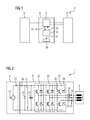
- a battery 4 and an electrical load in the form of a three-phase electric motor 6 via an electrical converter in the form of a three-phase inverter 8 are electrically connected to each other.
- the three-phase inverter 8 is accommodated in an inverter box 10.
- the circuit 2 may for example be part of a vehicle electrical system of a vehicle, not shown, in which the battery 4 as a rechargeable battery supplies the three-phase electric motor 6 as a drive unit of the vehicle with electrical energy.
- a battery voltage 12 is applied to the inverter 8.
- an intermediate circuit capacitor 14 is connected in parallel to the battery 4, which is charged by the battery voltage 12 to the battery voltage 12.
- the capacitor voltage 15 can be detected by a voltmeter 16, which is connected in parallel to the DC link capacitor 12.
- an ammeter 18 may be arranged, which detects the discharged from the battery 4 battery electric current 20.
- the inverter 8 includes three half-bridges 22 each generating an alternating current phase 24 for the three-phase electric motor 6 based on the battery current 20.
- Each half-bridge 22 has two series-connected switching elements, each switching element consisting of a switch 26, such as an IGBT (bipolar transistor with insulated gate electrode) and a freewheeling diode 28 connected in parallel thereto.
- a switch 26 such as an IGBT (bipolar transistor with insulated gate electrode)
- freewheeling diode 28 connected in parallel thereto.
- FIG. 2 only a switch 26 and a freewheeling diode 28 provided with a reference numeral.
- the magnitude of the currents in the AC phases 24 may be measured with a corresponding phase current meter 30. Since the sum of the measured values from the phase current meters 30 is zero, one of the alternating current phases 24 can be determined by calculation and, if appropriate, one of the phase current meters 30 can be dispensed with.
- the detected battery current 20 and the detected capacitor voltage 15 corresponding to the battery voltage 12 are provided to a device 32 in the inverter box 10 for monitoring the circuit 2.
- the device 32 is further provided to control the switches 26 of the inverter 8 based on drive signals 33.
- the device 32 checks based on the detected battery current 20 and the detected capacitor voltage 15 in a manner to be described, whether the circuit of the battery 4 and the electric motor 6 in the circuit 2 is faulty and has, for example, interruptions or short circuits.
- the device 32 outputs a corresponding error message 34.
- a fuse function 36 is actuated, which discharges the intermediate circuit capacitor 14 in a manner not shown.
- the device 32 determines the error message 34.
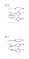
- FIG. 3 shows a first embodiment for determining the error message 34 with the device 32nd
- the device 32 cyclically varies the power flow through the circuit 2 in step 38 by means of the control signal 33, so that a comparatively small alternating current is superimposed in the circuit 2 whose peak-to-peak value can amount, for example, to 1% of the battery current.
- the device receives the capacitor voltage 15, which is detected by the voltmeter 16, and checks whether a pattern equivalent to the varied power flow is found in the capacitor voltage 15.
- the device 32 may, for example, correlate the pattern used to vary the power flow with the detected capacitor voltage 15.
- the capacitor voltage 15 can be multiplied by the pattern and then low-pass filtered. If the pattern in the capacitor voltage 15 is found as a result of the correlation, this is an indication that electrical power is transmitted to the electric motor 6 and no short circuit can be present. In this case, the device 32 continues the process at step 42. Alternatively, the device 32 outputs an error message 36 in step 44.
- step 42 the device 32 checks how high the fluctuations in the found pattern of the capacitor voltage 15 are. If the fluctuations exceed a certain threshold, then this is an indication that only the DC link capacitor 14 provides the electrical energy for the electric motor 6 and an interruption between the battery 4 and DC link capacitor 14 must be present. In this case, the device 32 outputs the error message 36 in step 44. If the fluctuations remain below the threshold, the device 32 determines that the functional state of the circuit 2 is error-free and restarts the process with step 38.
- FIG. 4 shows a second embodiment for determining the error message 34 with the device 32.
- FIG. 4 become too FIG. 3 same steps provided with the same reference numerals and not described again.
- Step 40 is replaced by Step 46 and Step 42 is replaced by Step 48.
- step 40 While in step 40, in the sensed capacitor voltage 15, the pattern of power flow variation has been sought, device 32 receives the battery current 20 in addition to the capacitor voltage in step 46 and calculates the impedance of the circuit between the link capacitor 14 and battery 4. The calculated impedance becomes compared against a lower threshold. If the calculated impedance is too low, this is an indication of a short circuit in the circuit between the DC link capacitor 14 and the battery 4 and the method accordingly outputs the error message 34 in step 44.
- step 48 is continued, in which the calculated impedance is compared against an upper threshold. If the calculated impedance is too high, this is an indication of an interruption in the circuit between the intermediate circuit capacitor 14 and the battery 4. The method also outputs the error message 34 in step 44 in this case. If the calculated impedance is between the lower and upper threshold values, the functional state of the circuit 2 is error-free and the method restarts with step 38.
Landscapes
- Engineering & Computer Science (AREA)
- Power Engineering (AREA)
- Transportation (AREA)
- Mechanical Engineering (AREA)
- Life Sciences & Earth Sciences (AREA)
- Sustainable Development (AREA)
- Sustainable Energy (AREA)
- Charge And Discharge Circuits For Batteries Or The Like (AREA)
Priority Applications (1)
| Application Number | Priority Date | Filing Date | Title |
|---|---|---|---|
| EP11182737A EP2572921A1 (fr) | 2011-09-26 | 2011-09-26 | Surveillance d'un circuit |
Applications Claiming Priority (1)
| Application Number | Priority Date | Filing Date | Title |
|---|---|---|---|
| EP11182737A EP2572921A1 (fr) | 2011-09-26 | 2011-09-26 | Surveillance d'un circuit |
Publications (1)
| Publication Number | Publication Date |
|---|---|
| EP2572921A1 true EP2572921A1 (fr) | 2013-03-27 |
Family
ID=44720686
Family Applications (1)
| Application Number | Title | Priority Date | Filing Date |
|---|---|---|---|
| EP11182737A Withdrawn EP2572921A1 (fr) | 2011-09-26 | 2011-09-26 | Surveillance d'un circuit |
Country Status (1)
| Country | Link |
|---|---|
| EP (1) | EP2572921A1 (fr) |
Citations (10)
| Publication number | Priority date | Publication date | Assignee | Title |
|---|---|---|---|---|
| EP0435405A1 (fr) * | 1989-12-22 | 1991-07-03 | TEUCO GUZZINI S.r.l. | Dispositif de sécurité électronique pour connexions de terre |
| US20020121902A1 (en) * | 2001-01-11 | 2002-09-05 | Nissan Motor Co., Ltd. | Ground detection apparatus for electric vehicle |
| US20030098671A1 (en) * | 2001-11-26 | 2003-05-29 | Visteon Global Technologies, Inc. | Anti-islanding detection scheme for distributed power generation |
| US20030156367A1 (en) * | 2002-02-01 | 2003-08-21 | Macbeth Bruce F. | Arc fault circuit interrupter with upstream impedance detector |
| DE102005061018A1 (de) * | 2005-12-19 | 2007-06-21 | Daimlerchrysler Ag | Vorrichtung und Verfahren zur Anschlussprüfung von Lautsprechern eines Audiosystems |
| US20070229091A1 (en) * | 2006-03-21 | 2007-10-04 | Kumar Ajith K | Method, apparatus and computer-readable code for detecting an incipient ground fault in an electrical propulsion system |
| EP1903651A1 (fr) * | 2005-07-12 | 2008-03-26 | Komatsu Ltd. | Détecteur de fuite de système d alimentation monté dans véhicule |
| US20100244850A1 (en) * | 2009-03-31 | 2010-09-30 | Honda Motor Co., Ltd. | Electric vehicle with ground fault detecting system |
| DE102009020178A1 (de) | 2009-05-06 | 2010-11-11 | Continental Automotive Gmbh | System zum Speichern von Energie |
| WO2011104848A1 (fr) * | 2010-02-25 | 2011-09-01 | 三菱電機株式会社 | Dispositif de conversion électrique |
-
2011
- 2011-09-26 EP EP11182737A patent/EP2572921A1/fr not_active Withdrawn
Patent Citations (10)
| Publication number | Priority date | Publication date | Assignee | Title |
|---|---|---|---|---|
| EP0435405A1 (fr) * | 1989-12-22 | 1991-07-03 | TEUCO GUZZINI S.r.l. | Dispositif de sécurité électronique pour connexions de terre |
| US20020121902A1 (en) * | 2001-01-11 | 2002-09-05 | Nissan Motor Co., Ltd. | Ground detection apparatus for electric vehicle |
| US20030098671A1 (en) * | 2001-11-26 | 2003-05-29 | Visteon Global Technologies, Inc. | Anti-islanding detection scheme for distributed power generation |
| US20030156367A1 (en) * | 2002-02-01 | 2003-08-21 | Macbeth Bruce F. | Arc fault circuit interrupter with upstream impedance detector |
| EP1903651A1 (fr) * | 2005-07-12 | 2008-03-26 | Komatsu Ltd. | Détecteur de fuite de système d alimentation monté dans véhicule |
| DE102005061018A1 (de) * | 2005-12-19 | 2007-06-21 | Daimlerchrysler Ag | Vorrichtung und Verfahren zur Anschlussprüfung von Lautsprechern eines Audiosystems |
| US20070229091A1 (en) * | 2006-03-21 | 2007-10-04 | Kumar Ajith K | Method, apparatus and computer-readable code for detecting an incipient ground fault in an electrical propulsion system |
| US20100244850A1 (en) * | 2009-03-31 | 2010-09-30 | Honda Motor Co., Ltd. | Electric vehicle with ground fault detecting system |
| DE102009020178A1 (de) | 2009-05-06 | 2010-11-11 | Continental Automotive Gmbh | System zum Speichern von Energie |
| WO2011104848A1 (fr) * | 2010-02-25 | 2011-09-01 | 三菱電機株式会社 | Dispositif de conversion électrique |
Similar Documents
| Publication | Publication Date | Title |
|---|---|---|
| EP1909368B1 (fr) | Agencement de commutation et procédé de surveillance d'isolation pour des applications de convertisseur | |
| DE102013227174B4 (de) | Vorrichtung und Verfahren zur Ermittlung eines Isolationswiderstandes einer Photovoltaikanlage | |
| EP3394948B1 (fr) | Onduleur à point de rupture de réseau et mesure de résistance d'isolement et procédé de mesure d'une résistance d'isolement | |
| EP2578876B1 (fr) | Système de pas pour une éolienne et procédé de fonctionnement d'un système de pas | |
| DE102016202021B3 (de) | Verfahren und Vorrichtungen zur Erkennung einer Unterbrechung einer Schutzleiterverbindung | |
| DE102013217748B4 (de) | Multifunktionale Oberwachung elektrischer Systeme in einem Kraftfahrzeug | |
| WO2011121035A1 (fr) | Réseau de bord pour un véhicule ainsi que dispositif de commande pour un réseau de bord | |
| EP4252013B1 (fr) | Méthode de détermination d'au moins une valeur actuelle de la capacité d'une y-capacité dans un réseau embarqué haute tension et unité de traitement électronique | |
| DE102019207920B4 (de) | Fahrzeugbordnetz mit einem Isolationsmonitor und Gleichspannungsladestation mit einem ladestationsseitigem Isolationsmonitor | |
| WO2020120307A1 (fr) | Circuit pour la détection d'erreurs dans un système haute tension non mis à la terre | |
| DE112016001332T5 (de) | Mehrphasenwandler | |
| EP2837012B1 (fr) | Procédé de vérification d'un point de coupure d'un onduleur photovoltaïque et onduleur photovoltaïque | |
| AT513866B1 (de) | Verfahren zur Prüfung einer Trennstelle eines Photovoltaik-Wechselrichters und Photovoltaik-Wechselrichter | |
| DE102013209142A1 (de) | Verfahren zur Ermittlung eines Isolationswiderstands eines mehrere Teilnetze umfassenden Energieversorgungsnetzwerks eines Fahrzeugs | |
| EP2637028B1 (fr) | Dispositif et procédé destinés à la vérification de batteries à haute tension | |
| EP3824524B1 (fr) | Procédé de vérification d'un point de séparation d'un onduleur photovoltaïque et un tel onduleur photovoltaïque | |
| EP2553482B1 (fr) | Circuit électrique de véhicule et commande pour ce circuit | |
| DE102017215981A1 (de) | Verfahren zum Betreiben einer Vorrangschaltung zum Koppeln zumindest eines Verbraucherausgangs mit zumindest zwei Quelleneingängen sowie Vorrangschaltung | |
| EP2572921A1 (fr) | Surveillance d'un circuit | |
| EP4252014A1 (fr) | Dispositif de surveillance pour une opération de secours d'urgence | |
| DE102017205477A1 (de) | Diagnoseverfahren für einen Wechselrichter, Wechselrichteranordnung und elektrisches Antriebssystem | |
| DE102024209198B4 (de) | Verfahren zum Überwachen von Isolationswiderständen und entsprechendes Steuergerät | |
| DE102015006608B4 (de) | Verfahren zum Betrieb einer Photovoltaikeinrichtung eines Kraftfahrzeugs und Kraftfahrzeug | |
| DE102024119211A1 (de) | Verfahren und Recheneinheit zum Überprüfen einer Zwischenkreiskapazität in einem Gleichspannungsnetz, Stromrichteranordnung und Antriebssystem | |
| DE102020211760A1 (de) | Verfahren zum Entladen von Entstörkondensatoren eines ungeerdeten Energie-versorgungsnetzes |
Legal Events
| Date | Code | Title | Description |
|---|---|---|---|
| PUAI | Public reference made under article 153(3) epc to a published international application that has entered the european phase |
Free format text: ORIGINAL CODE: 0009012 |
|
| AK | Designated contracting states |
Kind code of ref document: A1 Designated state(s): AL AT BE BG CH CY CZ DE DK EE ES FI FR GB GR HR HU IE IS IT LI LT LU LV MC MK MT NL NO PL PT RO RS SE SI SK SM TR |
|
| AX | Request for extension of the european patent |
Extension state: BA ME |
|
| 17P | Request for examination filed |
Effective date: 20130705 |
|
| RBV | Designated contracting states (corrected) |
Designated state(s): AL AT BE BG CH CY CZ DE DK EE ES FI FR GB GR HR HU IE IS IT LI LT LU LV MC MK MT NL NO PL PT RO RS SE SI SK SM TR |
|
| 17Q | First examination report despatched |
Effective date: 20170131 |
|
| RAP1 | Party data changed (applicant data changed or rights of an application transferred) |
Owner name: SIEMENS AKTIENGESELLSCHAFT |
|
| STAA | Information on the status of an ep patent application or granted ep patent |
Free format text: STATUS: THE APPLICATION IS DEEMED TO BE WITHDRAWN |
|
| 18D | Application deemed to be withdrawn |
Effective date: 20170613 |