EP3824710A2 - Unité de rangée agricole et procédé pour éliminer des résidus agricoles d'une rangée agricole - Google Patents
Unité de rangée agricole et procédé pour éliminer des résidus agricoles d'une rangée agricole Download PDFInfo
- Publication number
- EP3824710A2 EP3824710A2 EP20204518.3A EP20204518A EP3824710A2 EP 3824710 A2 EP3824710 A2 EP 3824710A2 EP 20204518 A EP20204518 A EP 20204518A EP 3824710 A2 EP3824710 A2 EP 3824710A2
- Authority
- EP
- European Patent Office
- Prior art keywords
- disk
- clearing
- axis
- drive
- soil
- Prior art date
- Legal status (The legal status is an assumption and is not a legal conclusion. Google has not performed a legal analysis and makes no representation as to the accuracy of the status listed.)
- Granted
Links
Images


Classifications
-
- A—HUMAN NECESSITIES
- A01—AGRICULTURE; FORESTRY; ANIMAL HUSBANDRY; HUNTING; TRAPPING; FISHING
- A01B—SOIL WORKING IN AGRICULTURE OR FORESTRY; PARTS, DETAILS, OR ACCESSORIES OF AGRICULTURAL MACHINES OR IMPLEMENTS, IN GENERAL
- A01B69/00—Steering of agricultural machines or implements; Guiding agricultural machines or implements on a desired track
- A01B69/02—Ridge-marking or like devices; Checkrow wires; Accessories therefor
- A01B69/024—Ridge-marking or like devices; Checkrow wires; Accessories therefor adapted to cut and form a ridge or forrow in the soil surface, e.g. with a disc
-
- A—HUMAN NECESSITIES
- A01—AGRICULTURE; FORESTRY; ANIMAL HUSBANDRY; HUNTING; TRAPPING; FISHING
- A01C—PLANTING; SOWING; FERTILISING
- A01C7/00—Sowing
- A01C7/006—Minimum till seeding
-
- A—HUMAN NECESSITIES
- A01—AGRICULTURE; FORESTRY; ANIMAL HUSBANDRY; HUNTING; TRAPPING; FISHING
- A01C—PLANTING; SOWING; FERTILISING
- A01C7/00—Sowing
- A01C7/08—Broadcast seeders; Seeders depositing seeds in rows
- A01C7/16—Seeders with other distributing devices, e.g. brushes, discs, screws or slides
-
- A—HUMAN NECESSITIES
- A01—AGRICULTURE; FORESTRY; ANIMAL HUSBANDRY; HUNTING; TRAPPING; FISHING
- A01B—SOIL WORKING IN AGRICULTURE OR FORESTRY; PARTS, DETAILS, OR ACCESSORIES OF AGRICULTURAL MACHINES OR IMPLEMENTS, IN GENERAL
- A01B79/00—Methods for working soil
- A01B79/005—Precision agriculture
-
- A—HUMAN NECESSITIES
- A01—AGRICULTURE; FORESTRY; ANIMAL HUSBANDRY; HUNTING; TRAPPING; FISHING
- A01C—PLANTING; SOWING; FERTILISING
- A01C19/00—Arrangements for driving working parts of fertilisers or seeders
- A01C19/02—Arrangements for driving working parts of fertilisers or seeders by a motor
-
- A—HUMAN NECESSITIES
- A01—AGRICULTURE; FORESTRY; ANIMAL HUSBANDRY; HUNTING; TRAPPING; FISHING
- A01C—PLANTING; SOWING; FERTILISING
- A01C5/00—Making or covering furrows or holes for sowing, planting or manuring
- A01C5/06—Machines for making or covering drills or furrows for sowing or planting
-
- Y—GENERAL TAGGING OF NEW TECHNOLOGICAL DEVELOPMENTS; GENERAL TAGGING OF CROSS-SECTIONAL TECHNOLOGIES SPANNING OVER SEVERAL SECTIONS OF THE IPC; TECHNICAL SUBJECTS COVERED BY FORMER USPC CROSS-REFERENCE ART COLLECTIONS [XRACs] AND DIGESTS
- Y02—TECHNOLOGIES OR APPLICATIONS FOR MITIGATION OR ADAPTATION AGAINST CLIMATE CHANGE
- Y02P—CLIMATE CHANGE MITIGATION TECHNOLOGIES IN THE PRODUCTION OR PROCESSING OF GOODS
- Y02P60/00—Technologies relating to agriculture, livestock or agroalimentary industries
- Y02P60/20—Reduction of greenhouse gas [GHG] emissions in agriculture, e.g. CO2
Definitions
- the present disclosure relates to an agricultural row unit, and in particular, to a row unit for clearing crop residue or other material from an agricultural row of a field.
- An agricultural implement such as a row crop planter may include a row unit adapted to apply seed or fertilizer to a field.
- Some agricultural machines are capable of clearing crop residue, soil, or other debris from a row of a field. With some of these machines, clearing-disks are located forward of the seed distribution area so that the residue may be cleared from a row prior to the seed being planted.
- the clearing-disks may extend into the soil and may be rotated by the soil as the machine moves over the soil. It may be desirable to change the rotational speed or position of one or more of the clearing-disks, which may present challenges, especially when the clearing-disks are driven by soil as the machine moves over the soil.
- an agricultural row unit that is adapted to be moved in a forward direction over soil to clear agricultural residue includes: an attachment frame; a drive clearing-disk coupled to the attachment frame for rotation about a first axis; and a driven clearing-disk coupled to the attachment frame for rotation about a second axis offset from the first axis; wherein the drive clearing-disk is drivingly coupled to the driven clearing-disk to rotate the driven clearing-disk about the second axis.
- the agricultural row unit includes a motor coupled to the drive clearing-disk and configured to rotate the drive clearing-disk about the first axis.
- the agricultural row unit includes a controller configured to adjust a speed of rotation of the motor in response to at least one of a speed of forward movement of the agricultural row unit over the soil, a height of the drive clearing-disk relative to a surface of the soil, a height of the driven clearing-disk relative to a surface of the soil, an amount of crop residue in an agricultural row, and a downforce pressure on a portion of the agricultural row unit.
- the drive clearing-disk extends radially outward away from the first axis to define an outer boundary of the drive clearing-disk.
- the outer boundary of the drive clearing-disk includes a lowermost point relative to a surface of the soil.
- the driven clearing-disk extends radially outward away from the second axis to define an outer boundary of the driven clearing-disk.
- the outer boundary of the driven clearing-disk includes a lowermost point relative to the surface of the soil.
- the lowermost point of the driven clearing-disk is positioned above the lowermost point of the drive clearing-disk during operation of the agricultural row unit.
- the lowermost point of the drive clearing-disk is positioned below the surface of the soil during operation of the agricultural row unit.
- the lowermost point of the driven clearing-disk is positioned above the surface of the soil during operation of the agricultural row unit.
- the outer boundary of the drive clearing-disk includes a forward-most point relative to the forward direction of movement of the agricultural planter.
- the outer boundary of the driven clearing-disk includes a forward-most point relative to the forward direction of movement of the agricultural planter.
- the forward-most point of the drive clearing-disk is positioned rearwardly of the forward-most point of the driven clearing-disk during operation of the agricultural planter.
- the first axis and the second axis are not contained in the same plane.
- the agricultural row unit includes a gear assembly drivingly coupled between the drive clearing-disk and the driven clearing-disk.
- the gear assembly When the drive clearing-disk rotates at a first speed the gear assembly is configured to rotate the driven clearing-disk at a second speed greater than the first speed.
- the gear assembly includes a slip clutch reconfigurable between (i) a first mode in which the slip clutch is engaged with the drive clearing-disk and the driven clearing-disk and facilitates rotation of the driven clearing-disk, and (ii) a second mode in which a portion of the slip clutch is disengaged from the driven clearing-disk to allow the drive clearing-disk to rotate independently of the driven clearing-disk.
- the driven disk is movable relative to the attachment frame between (i) a first position in which a first disk-to-disk angle is defined by the intersection of first axis and the second axis and (ii) a second position in which a second disk-to-disk angle is defined by the intersection of first axis and the second axis.
- the second disk-to-disk angle is different than the first disk-to-disk angle.
- the driven disk is movable relative to the attachment frame between (i) a third position in which a first disk-to-soil angle is defined between the second axis and a plane approximating the surface of the soil (ii) a fourth position in which a second disk-to-soil angle is defined between the second axis and the plane approximating the surface of the soil.
- the second disk-to-soil angle is different than the first disk-to-soil angle.
- a controller is coupled to the driven clearing-disk, and the controller is configured to move the driven disk between the first and second positions and between the third and fourth positions.
- a method of clearing agricultural residue from an agricultural row includes: moving an agricultural row unit over soil in a forward direction; operating a motor coupled to a drive clearing-disk at an operating speed to rotate the drive clearing-disk about a first axis and to rotate a driven clearing-disk about a second axis offset from the first axis; adjusting the operating speed of the motor in response to at least one: of a speed of the agricultural row unit in the forward direction, a height of the drive clearing-disk relative to a surface of the soil, a height of the driven clearing-disk relative to the surface of the soil, an amount of crop residue in the row, and a downforce pressure on a portion of the agricultural row unit.
- operating a motor coupled to a drive clearing-disk at an operating speed to rotate the drive clearing-disk about a first axis and to rotate a driven clearing-disk about a second axis offset from the first axis includes: engaging the drive clearing-disk with a gear assembly driven by the drive clearing-disk; and engaging the gear assembly with the driven clearing-disk to drive rotation of the driven clearing-disk about the second axis.
- the method includes rotating the drive clearing-disk at a first speed; and rotating the driven clearing-disk at a second speed greater than the first speed.
- the method includes adjusting a position of the second axis relative to a position of the first axis.
- operating a motor coupled to a drive clearing-disk at an operating speed to rotate the drive clearing-disk about a first axis and to rotate a driven clearing-disk about a second axis offset from the first axis includes: positioning a lowermost point of an outer boundary of the drive clearing-disk at a first height relative to the surface of the soil; and positioning a lowermost point of an outer boundary of the driven clearing-disk at a second height positioned above the first height relative to the surface of the soil.
- positioning a lowermost point of an outer boundary of the driven clearing-disk at a second height positioned above the first height relative to the surface of the soil includes: positioning the lowermost point of the outer boundary of the driven disk above or substantially aligned with the surface of the soil.
- operating a motor coupled to a drive clearing-disk at an operating speed to rotate the drive clearing-disk about a first axis and to rotate a driven clearing-disk about a second axis offset from the first axis includes: positioning a forwardmost point of the outer boundary of the drive clearing-disk at a first position; and positioning a forwardmost point of the outer boundary of the driven clearing-disk at a second position located forward of the first position.
- the method includes adjusting an angle defined by the intersection of second axis and the surface of the soil in response to at least one of: a speed of the agricultural row unit along the row, amount of agricultural residue in the row, and a downforce pressure on a portion of the agricultural row unit.
- an agricultural row unit adapted to be moved in a forward direction over soil to clear agricultural residue includes: an attachment frame; a drive clearing-disk coupled to the attachment frame for rotation about a first axis; a driven clearing-disk coupled to the attachment frame for rotation about a second axis offset from the first axis; and a motor coupled to at least one of the drive clearing-disk and the driven-clearing disk configured to rotate the at least one of the drive clearing-disk and the driven-clearing disk about the first axis or the second axis.
- an agricultural row unit adapted to be moved in a forward direction over soil to clear agricultural residue includes: an attachment frame; a plurality of clearing-disks including at least: a drive clearing-disk coupled to the attachment frame for rotation about a first axis, a driven clearing-disk coupled to the attachment frame for rotation about a second axis offset from the first axis; and a plurality of motors including at least: a first motor coupled to the drive clearing-disk and configured to rotate drive-clearing disk about the first axis, and a second motor coupled to the driven clearing-disk and configured to rotate the driven-clearing disk about the second axis.
- an agricultural row unit is adapted to be moved horizontally over soil to clear agricultural residue, and the agricultural row unit includes: an attachment plate; a linkage assembly having a first end pivotably coupled to the attachment plate and a second end opposite the first end; an attachment frame pivotably coupled to the second end of the linkage assembly; a clearing brush coupled to the attachment frame for rotation about a longitudinal axis of the clearing brush; and a motor drivingly coupled to the clearing brush and configured to rotate the clearing brush about the longitudinal axis; wherein the longitudinal axis of the clearing brush defines a vector having a horizontal component and a vertical component that is greater than the horizontal component.
- the agricultural row unit includes a lateral shield (i) pivotably coupled to the attachment frame for movement relative to the attachment frame in the vertical direction and (ii) adjustable between a plurality of lateral positions in each of which the lateral shield is spaced apart a different lateral distance from the attachment frame.
- the agricultural row unit includes a knock-off shield coupled to the attachment frame, spaced apart from the lateral shield, and arranged a predefined distance away from the clearing brush such that the knock-off shield interacts with and removes residue from the clearing brush when the clearing brush is rotated about the longitudinal axis.
- a planter row unit or agricultural row unit 100 is shown.
- the row unit 100 is adapted for use with an agricultural implement.
- the row unit 100 may be coupled to a main frame of the agricultural implement via a parallel linkage 116 or another suitable linkage.
- the parallel linkage 116 allows for independent vertical movement of the planting row unit 100 as it traverses along uneven ground.
- Each planter row unit 100 may include a row unit shank 128 to which a seed hopper 120 is coupled.
- the seed hopper 120 may store seed to be planted by the planter row unit 100 during a planting operation. Seed may be deposited within a trench or furrow formed by opening disks 122.
- the depth at which the opening disk or disks 122 is set relative to the soil may be set by a gauge wheel or wheels 124 and a depth-setting mechanism.
- a closing wheels 126 may be further coupled to the shank 128 of the row unit 100 in order to close or cover the trench with soil.
- the row unit 100 may also include a fertilizer applicator including a hopper or container 108 for storing fertilizer, e.g., dry granular fertilizer, or a tank for storing gaseous or liquid fertilizer.
- the fertilizer applicator may further include a cutting disk positionable at a defined depth into the soil to form a furrow or trench therein.
- the fertilizer applicator may further include a gauge used to set the depth of the furrow or trench to be formed by the cutting disk. It should be appreciated that the cutting disk and the opening disks 122 described above are discrete from clearing disks, which will be described below in greater detail as clearing disks 130.
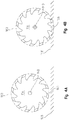
- the agricultural row unit 100 further includes one or more clearing disks 130.
- the clearing disks 130 are configured to clear crop residue, soil, or other material from a row of the field to be planted and fertilized.
- the clearing disks 130 may be included in a clearing assembly 132.
- the clearing assembly 132 includes an attachment plate 138, an attachment frame 135, a linkage assembly 137 coupled therebetween, a drive clearing-disk 134, and a driven clearing-disk 136.
- the attachment plate 138 is coupled to the row unit shank 128 (or otherwise arranged on the row unit 100) in a forward-facing orientation, such that the clearing disks 130 are arranged to be pushed by the attachment plate 138 in the forward direction 105 during forward movement of the row unit 100.
- the drive clearing-disk 134 is configured to drive rotation of the driven clearing-disk 136.
- the drive clearing-disk 134 is coupled to the attachment frame 135 and configured to rotate about a first axis 140.
- the driven clearing-disk 136 is coupled to the attachment frame 135 and configured to rotate about a second axis 142.
- the second axis 142 is offset from the first axis 140 (i.e., the second axis 142 is different than the first axis 140).
- the clearing assembly 132 also includes a final drive assembly configured to drive rotation of the drive clearing-disk 134.
- the final drive assembly can be driven by a drive unit 144 or other power mechanism.
- the drive unit 144 is an electric motor included in the clearing assembly 132.
- the row unit 100 may include a plurality of clearing assemblies 132, and each clearing assembly 132 may include a separate drive unit 144. Further, the row unit 100 may move along several agricultural rows of field simultaneously. As such, each individual agricultural row may be cleared by a corresponding clearing assembly 132 having a corresponding drive unit 144.
- each clearing assembly 132 may include a controller 146 electrically coupled to the drive unit 144.
- the controller 146 is configured to adjust the drive speed of the drive unit 144 in response to one or more factors including: a speed of forward movement of the agricultural row unit 100 over the soil, a height of the drive clearing-disk 134 relative to a surface of the soil 148, a height of the driven clearing-disk 136 relative to a surface of the soil, an amount of crop residue in an agricultural row of the field, and a downforce on a portion the row unit 100.
- each clearing assembly 132 may further include a sensor 150 electrically coupled to the controller 146.
- the sensor 150 is configured to identify the amount of crop residue or other material in an agricultural row of the field and transmit a signal to the controller 146 indicative of the amount of crop residue or other material.
- the controller 246 may also be configured to adjust the drive speed in response to a predetermined prescribed operating plan for the field. In other, embodiments, a user may adjust the drive speed of the drive unit 144 via a user input separate from the controller 146.
- surface of the soil as used herein means an imaginary plane approximating a surface of soil, upon which the row unit 100 is traveling as the row unit 100 move moves horizontally along an agricultural row in the field.
- the clearing assembly 132 further includes a gear assembly 151 that is coupled between the drive clearing-disk 134 and the driven clearing-disk 136.
- the gear assembly 151 is configured to transmit rotational motion from the drive clearing-disk 134 to the driven clearing-disk 136.
- the gear assembly 151 is drivingly coupled between the drive clearing-disk 134 and the driven clearing-disk 136.
- the gear assembly 151 includes a number of disk-connecting gears 152 (such as bevel gears and spur gears) for transmitting rotational motion from the drive clearing-disk 134 to the driven clearing-disk 136.
- the gear assembly 151 includes gear-step unit 156 configured rotate the driven clearing-disk 136 at different speed than that of the drive clearing-disk 134.
- the drive clearing-disk 134 is rotated by the drive unit 144 (or by other means) at a first speed
- the gear-step unit 156 is configured to rotate the driven clearing-disk 136 at a second speed greater than the first speed.
- the gear assembly 151 includes a slip clutch 158 including a first portion fixed to the drive clearing disk 134 and a second portion fixed to the driven clearing-disk 136.
- the slip clutch 158 is reconfigurable between a first mode and a second mode. In the first mode, the slip clutch 158 is engaged with the drive clearing-disk 134 and the driven clearing-disk 136, and the slip clutch 158 facilitates rotation of the driven clearing-disk 136 by the drive clearing-disk 134. In the second mode, a first portion of the slip clutch 158 disengaged from the second portion of the slip clutch 158 to allow the drive clearing-disk 134 to rotate independently of the driven clearing-disk 136.
- the driven clearing-disk 136 may cease rotation and the drive clearing-disk 134 may continue to rotate without damaging the gear assembly 151 or other components of the clearing assembly 132.
- the drive clearing-disk extends 134 radially outward away from the first axis 140 to define an outer boundary 160 of the drive clearing-disk 134.
- the driven clearing-disk 136 extends radially outward away from the second axis 142 to define an outer boundary 162 of the driven clearing-disk 136.
- the outer boundary 160 of the drive clearing-disk 134 includes a lowermost point 166 relative to the surface of the soil 148.
- the outer boundary 162 of the driven clearing-disk 136 includes a lowermost point (not shown) relative to the surface of the soil 148.
- the lowermost point 166 of the drive clearing-disk 134 is positioned above the surface of the soil 148 during operation of the row unit 100.
- the drive clearing-disk 134 is positioned below the surface of the soil 148, and as the row unit 100 moves through the field, the drive clearing-disk 134 contacts the soil or a sub-surface of the soil causing rotation of the drive clearing-disk 134.
- the drive clearing-disk 134 is driven by the soil while the driven clearing-disk 136 is driven by the drive clearing-disk 134.
- the lowermost point of the driven clearing-disk 136 and the lowermost point 166 of the drive clearing-disk 134 are positioned at different heights.
- the lowermost point of the driven clearing-disk 136 may be positioned above the lowermost point 166 of the drive clearing-disk 134.
- the outer boundary 160 of the drive clearing-disk 134 includes a forward-most point 170.
- forward is used relative to the forward direction of movement of the agricultural planter, as shown by the arrow 105.
- the outer boundary 162 of the driven clearing-disk 136 includes a forward-most point 172.
- the forward-most point 170 of the drive clearing-disk 134 is positioned rearwardly of the forward-most point 172 of the driven clearing-disk 136.
- the lowermost point of the driven clearing-disk 136 is movable relative to the lowermost point 166 of the drive clearing-disk 136.
- forward-most point 170 of the drive clearing-disk 134 movable relative to the forward-most point 172 of the driven clearing-disk 136.
- the clearing assembly 132 may include a first linear actuator 155 coupled to and configured to move the drive clearing-disk 134 and a second linear actuator 157 coupled to and configured to move the driven clearing-disk 136, as shown in Fig. 3 .
- the first and second linear actuators 155, 157 may be configured to facilitate sliding, rotational, or complex motion of the disks 134, 136. Such motion may be facilitated relative to the ground 148, the attachment frame 135, or in association with one disk relative to the other disk.
- each linear actuator 155, 157 may include a cam (such as an elliptical cam) connected to an electronic motor (such as a stepper motor) configured to move the disk 134, 136.
- each linear actuator 155, 157 may include lead screw or worm gear configured to move the disks 134, 136.
- the clearing assembly 132 may include a controller 174 electrically coupled to one or both of the drive clearing-disk 134 and the driven clearing-disk 136.
- the controller 174 may be discrete from the controller 146, in communication with the controller 146, or included in the controller 146.
- Each controller 146, 174 may be controlled by a master controller or may operate independently.
- the controller 174 is configured to adjust the forward-most point 172 of the driven clearing-disk 136 relative to the forward-most point 170 of the drive clearing-disk 134.
- the controller 174 is configured to adjust the lowermost point of the driven clearing-disk 136 relative to the lowermost point 166 of the drive clearing-disk 136. In some embodiments, the controller 174 is configured to adjust the height of one or both of the disks 134, 136 in response any number of the following factors including: a speed of forward movement of the agricultural row unit 100 over the soil, a height of the drive clearing-disk 134 relative to the surface of the soil 148, a height of the driven clearing-disk 136 relative to a surface of the soil, an amount of crop residue in an agricultural row of the field, and a downforce on a portion the row unit 100.
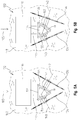
- the first axis 140 forms a disk-to-disk angle ⁇ with the second axis 142.
- the angle ⁇ is approximately 120 degrees; however, in other positions of the drive clearing-disk 134 or the driven clearing-disk 136 the angle ⁇ may have a different magnitude.
- the driven clearing-disk 136 is movable relative to the attachment frame 135 (and movable relative to the drive clearing-disk 134) between (i) a first position in which a first disk-to-disk angle ⁇ is defined between the intersection of the first axis 140 and the second axis 142 and (ii) a second position in which a second disk-to-disk angle ⁇ is defined by the intersection of first axis 140 and the second axis 142.
- the second disk-to-disk angle ⁇ has a different magnitude than the first disk-to-disk angle ⁇ . While the above description recites that that the driven clearing-disk 136 is movable, it should also be appreciated that the drive clearing-disk 134 may also be movable to vary the magnitude of the angle ⁇ .
- the second axis 142 forms a disk-to-soil angle ⁇ with the surface of the soil 148.
- the angle ⁇ is zero degrees; however, in other positions (such as the position shown in Fig. 6B ), the angle ⁇ can be a non-zero angle.
- the driven clearing-disk 136 is movable relative to the attachment frame 135 between (i) a third position in which a first disk-to-soil angle ⁇ is defined between the second axis 142 and the surface of the soil 148 and (ii) a fourth position in which a second disk-to-soil angle ⁇ is defined between the second axis 142 and the surface of the soil 148.
- the second disk-to-soil angle ⁇ has a different magnitude than the first disk-to-disk angle ⁇ .
- the disk-to-disk angle ⁇ and the disk-to-soil angle ⁇ can both be adjusted, in some positions the drive clearing-disk 134 and the driven clearing-disk 136 are not contained in a common plane. In other positions, the drive clearing-disk 134 and the driven clearing-disk 136 are contained in a common plane.
- the controller 174 is configured to adjust the disk-to-disk angle ⁇ . In some embodiments, the controller 174 is configured to adjust the disk-to-soil angle ⁇ . In some embodiments, the controller 174 is configured to adjust one or both of the disk-to-disk angle ⁇ or the disk-to-soil angle ⁇ in response any number of the following factors including: a speed of forward movement of the agricultural row unit 100 over the soil, a height of the drive clearing-disk 134 relative to the surface of the soil 148, a height of the driven clearing-disk 136 relative to a surface of the soil, an amount of crop residue in an agricultural row of the field, and a downforce on a portion the row unit 100.
- each of: the disk-to-disk height, the disk-to-soil height, the relative to forward-to-rearward positioning of the disks 143, 136, the disk-to-disk angle ⁇ , and the disk-to-soil angle ⁇ can be adjusted by one or more controllers.
- a user may manually adjust the heights, angles, or positions of the drive clearing-disk 134 and the driven clearing-disk 136.
- the agricultural row unit 100 includes: the attachment frame 135, the drive clearing-disk 134 coupled to the attachment frame 135 for rotation about the first axis 140, and a driven clearing-disk 136 coupled to the attachment frame 135 for rotation about the second axis 142; however, the motor is coupled to only one of the drive clearing-disk 134 and the driven-clearing disk 136.
- the agricultural row unit 100 includes only a single clearing disk 130, and the motor is coupled to the single clearing disk 130 to drive rotation of the clearing disk about a single-disk axis of rotation.
- the agricultural row unit 100 includes: the attachment frame 135; a plurality of clearing-disks 130 including at least a first clearing-disk (such as the clearing disk 134 coupled to the attachment frame 135 for rotation about the first axis 140).
- the motor may include a second clearing-disk (such as disk 136 coupled to the attachment frame 135 for rotation about the second axis 142).
- the agricultural row unit 100 may further include a plurality of motors including at least: a first motor coupled to the first clearing disk and configured to rotate the first clearing disk about the first axis.
- the plurality of motors may include a second motor coupled to the second clearing disk and configured to rotate the second clearing disk about the second axis.
- the plurality of motors may include additional motors and the plurality of clearing disks may include additional disks coupled to the additional motors. In the embodiments described above, the plurality of disks may be driven one or more motors of the plurality of motors.
- the clearing assembly 232 includes an attachment plate 234, an attachment frame 236, a linkage assembly 238 coupled therebetween, and a clearing brush 240 coupled to the attachment frame 236.
- the attachment plate 234 is arranged on the agricultural implement in a rearward-facing orientation, such that the clearing brush 240 is arranged to be pulled by the attachment plate 234 in the forward direction 105 during forward movement of the row unit 100.
- the clearing assembly 232 is configured to rest on and move forwardly along the surface of the soil 148 during operation of the row unit 100.
- the clearing assembly 232 further includes a cover 235 arranged to protect a drive unit or other components from debris or residue that may be encountered during forward movement of the row unit 100.
- the clearing assembly 232 also includes a final drive assembly configured to drive rotation of the clearing brush 240. As shown in Fig. 8 , the final drive assembly can be driven by a drive unit 244 or other power mechanism.
- the drive unit 244 is an electric motor included in the clearing assembly 232.
- the row unit 100 may include a plurality of clearing assemblies 232, and each clearing assembly 232 may include a separate drive unit 244. Further, the row unit 100 may move along several of agricultural rows of field simultaneously. As such, each individual agricultural row may be cleared by corresponding clearing assembly 232 having a corresponding drive unit 244.
- each clearing assembly 232 may include a controller 246 electrically coupled to the drive unit 244.
- the controller 246 is configured to adjust the drive speed of the drive unit 244 in response to one or more factors including: a speed of forward movement of the agricultural row unit 100 over the soil, an amount of crop residue in an agricultural row of the field, and a downforce on a portion the row unit 100.
- the sensor 248 is configured to identify the amount of crop residue or other material in an agricultural row of the field and transmit a signal to the controller 246 indicative of the amount of crop residue or other material.
- the controller 246 may also be configured to adjust the drive speed in response to a predetermined prescribed operating plan for the field.
- each clearing assembly 232 may further include a sensor 248 electrically coupled to the controller 246.
- a user may adjust the drive speed of the drive unit 244 via a user input separate from the controller 246.
- the linkage assembly 232 includes first and second pivotable ends 237, 239.
- the linkage assembly 238 may include fours bars that are each pivotably coupled at their first ends 237 to the attachment frame 236 and at their second ends 239 to the attachment plate 234. Because the linkage assembly 238 is pivotable at both ends 237, 239, the linkage assembly 238 facilitates vertical travel of the clearing brush 240 relative to the row unit shank 128. Thus, as a nose (not shown) of the clearing brush 240 rests on and is moved over uneven soil, the linkage assembly 238 facilitates vertical movement of the clearing brush 240 relative to the row unit shank 128. It should be appreciated, that while a four-bar linkage assembly is shown in Fig. 8 , other linkage assemblies may be used with the row unit 100, so long as those linkage assemblies facilitates vertical travel of the clearing brush 240.
- the clearing brush 240 is configured to rotate about its longitudinal axis 247.
- the longitudinal axis 247 of the clearing brush 240 defines a vector 249 having a horizontal component and a vertical component that is greater than the horizontal component.
- vertical component and horizontal component are meant to refer to the vertical component of extension and the horizontal portion of extension.
- a brush with a longitudinal axis having a vertical component equal to its horizontal component would be a brush with a longitudinal axis disposed at a 45 degree angle relative to the surface of the soil 148.
- the clearing brush 240 shown in Fig. 9 is disposed at an angle ⁇ relative to the surface of the soil 148, and the angle ⁇ is greater than 45 degrees.
- the clearing assembly 232 includes a lateral shield 250 and a knock-off shield 252.
- the lateral shield 250 is pivotably coupled to the attachment frame 236 for movement relative to the attachment frame 236 in the vertical direction.
- the clearing assembly 232 includes a lateral-connecting unit 254 including a bracket 256, a first arm 258, and a second arm 260.
- the bracket 256 is coupled to the attachment frame 236 via a plurality fasteners, and when the bracket 256 is coupled to the attachment frame 236, the bracket 256 is fixed relative to the attachment frame 236.
- the first arm 258 is pivotably coupled to the bracket 256 for rotation about an axis 237 transverse to the clearing assembly 232. Pivoting movement of the first arm 258 relative to the bracket 256 moves the lateral shield 250 vertically relative to the attachment frame 236.
- the second arm 260 is removably coupled to the first arm 258 of the lateral shield 250.
- the first arm 258 includes a plurality of apertures 264 (for example three rows of three), and the second arm 260 includes a plurality of apertures 266 (for example one row of two).
- a plurality of fasteners may be inserted into each of the pluralities of apertures 264, 266 to removably couple the first arm 258 to the second arm 260.
- the second arm 260 is further coupled to the lateral shield 250 at a rotational axis 262 of the lateral shield 250.
- the lateral shield 250 is moveable between (a) a plurality of lateral positions in each of which the lateral shield 250 is spaced apart a different lateral distance from the longitudinal axis 247 of the clearing brush 240, and between (b) a plurality of axial positions in each of which the lateral shield 250 is spaced apart a different forward-rearward distance from the longitudinal axis 247 of the clearing brush 240.
- clearing brush 240 As clearing brush 240 rotates about its longitudinal axis 247, it thrusts residue laterally away from the longitudinal axis 247 toward the lateral shield 250.
- the lateral shield 250 is aligned vertically with at least a portion of the clearing brush 240. As such, the residue thrusted toward the lateral shield 250 is prevented from moving laterally beyond the lateral shield 250.
- the knock-off shield 252 is coupled to the attachment frame 236 and configured to contact the clearing brush 240 to remove residue from the clearing brush 240 when the clearing brush 240 is rotated about its longitudinal axis 247.
- a connecting arm 268 is coupled between the attachment frame 236 and the knock-off shield 252.
- the knock-off shield 252 includes a plurality of slots 270 and the connecting arm includes a plurality of apertures 272 (see Fig. 9 ).
- the slots 270 and apertures 272 are configured to receive a plurality of fasteners to couple the knock-off shield 252 to the connecting arm 268.
- the slots 270 may be described as axially-extending slots 270.
- the knock-off shield 252 can slide axially relative to the connecting arm 268 to adjust the axial position of the knock-off shield 252 relative to the clearing brush 240.
- the knock-off shield 252 may be arranged a predefined distance away from the longitudinal axis 247 of the clearing brush 240. The distance may be reduced to allow a greater portion of the clearing brush 240 to contact the knock-off shield 252 during rotation of the clearing brush 240. The distance may be increased such that a lesser portion of the clearing brush 240 contacts the knock-off shield 252 during rotation of the clearing brush 240.
- a cleared portion of residue is formed between the lateral shield 240 and the knock-off shield 252 as the row unit 100 moves in the forward direction with the clearing brush 240 rotating about its longitudinal axis 247.
- the width of the cleared portion of residue can be adjusted by adjusting the lateral position of the lateral shield 250.
Landscapes
- Life Sciences & Earth Sciences (AREA)
- Soil Sciences (AREA)
- Environmental Sciences (AREA)
- Engineering & Computer Science (AREA)
- Mechanical Engineering (AREA)
- Soil Working Implements (AREA)
- Cleaning In General (AREA)
Applications Claiming Priority (2)
| Application Number | Priority Date | Filing Date | Title |
|---|---|---|---|
| US201962928600P | 2019-10-31 | 2019-10-31 | |
| US17/062,802 US11825762B2 (en) | 2019-10-31 | 2020-10-05 | Powered clearing-disks, control system, and method of use |
Publications (3)
| Publication Number | Publication Date |
|---|---|
| EP3824710A2 true EP3824710A2 (fr) | 2021-05-26 |
| EP3824710A3 EP3824710A3 (fr) | 2021-10-13 |
| EP3824710B1 EP3824710B1 (fr) | 2024-10-30 |
Family
ID=73037880
Family Applications (2)
| Application Number | Title | Priority Date | Filing Date |
|---|---|---|---|
| EP20204518.3A Active EP3824710B1 (fr) | 2019-10-31 | 2020-10-29 | Unité de rangée agricole et procédé pour éliminer des résidus agricoles d'une rangée agricole |
| EP20204524.1A Active EP3815493B1 (fr) | 2019-10-31 | 2020-10-29 | Unité de rangée agricole |
Family Applications After (1)
| Application Number | Title | Priority Date | Filing Date |
|---|---|---|---|
| EP20204524.1A Active EP3815493B1 (fr) | 2019-10-31 | 2020-10-29 | Unité de rangée agricole |
Country Status (3)
| Country | Link |
|---|---|
| US (2) | US11825762B2 (fr) |
| EP (2) | EP3824710B1 (fr) |
| BR (1) | BR102020021599A2 (fr) |
Families Citing this family (8)
| Publication number | Priority date | Publication date | Assignee | Title |
|---|---|---|---|---|
| US11140803B2 (en) * | 2019-09-16 | 2021-10-12 | Cnh Industrial America Llc | System and method for rotationally driving ground engaging tools of an agricultural implement |
| US11579590B2 (en) | 2019-10-31 | 2023-02-14 | Deere & Company | Wireless mobile work machine component detection and control system |
| US12063882B2 (en) | 2019-10-31 | 2024-08-20 | Deere & Company | Volumetric metering system with improved roller detection |
| US12342739B2 (en) * | 2021-02-17 | 2025-07-01 | Cnh Industrial America Llc | System and method for controlling the operation of a row cleaning device of a seed-planting implement |
| US12284936B2 (en) | 2021-03-08 | 2025-04-29 | Deere & Company | Row unit plugging detection and control system |
| US12274206B2 (en) | 2021-07-23 | 2025-04-15 | Tribine Industries, LLC | Universal crop head assembly and its use in harvesting crops |
| US12543624B2 (en) * | 2021-10-05 | 2026-02-10 | Tribine Industries Llc | Seedbed preparation method and mechanism |
| US12329048B2 (en) * | 2023-08-15 | 2025-06-17 | Tribine Industries, LLC | Articulated combine having rear module with seedbed preparation mechanism |
Family Cites Families (17)
| Publication number | Priority date | Publication date | Assignee | Title |
|---|---|---|---|---|
| US2906080A (en) * | 1957-02-12 | 1959-09-29 | Sr James A Light | Lawn edging attachment for tractors |
| US2969601A (en) * | 1959-03-13 | 1961-01-31 | Mcmaster James Herbert | Channel clearing machine |
| US4483401A (en) | 1982-09-30 | 1984-11-20 | Acra-Plant, Inc. | Trash clearing assembly for farm implements |
| FR2646321A1 (fr) | 1989-04-27 | 1990-11-02 | Lagrange Jean Claude | Decavaillonneuse electro-hydraulique notamment pour vignes |
| US4989676A (en) * | 1990-01-16 | 1991-02-05 | Rogers Billy G | Sweeper system for lawn mowing |
| US5050372A (en) | 1990-07-11 | 1991-09-24 | Heiskell Merle L | Fence row cleaner |
| CA2023798C (fr) | 1990-08-22 | 1994-03-29 | Derek Sidders | Dispositif de melange pour le labourage |
| US5076180A (en) | 1990-10-15 | 1991-12-31 | Yetter Manufacture Company | Trash clearing brush unit for a planter unit |
| US5507351A (en) | 1994-01-25 | 1996-04-16 | Martin; Howard | Cleaner for tined wheels |
| CA2629476C (fr) | 2008-04-18 | 2010-07-13 | Straw Track Manufacturing Inc. | Elimination des residus pour instruments aratoires |
| CA2673265A1 (fr) | 2009-04-15 | 2010-10-15 | Peter Dillon | Reduction de l'accumulation des residus de recolte sur les dents |
| ITMN20090015A1 (it) | 2009-05-28 | 2010-11-29 | Gonzaga Aliana Guerrieri | Attrezzo multifunzione per operazioni contemporanee motorizzate di pulizia, scerbatura, fertilizzazione, zappatura ed altre al piede di filari di piante, in particolare di vigneti e frutteti |
| CA2885452A1 (fr) | 2015-03-19 | 2016-09-19 | David Robert Hundeby | Dispositif de coupe de residus pour machine agricole |
| CA2889850C (fr) | 2015-04-29 | 2017-05-30 | Seedmaster Manufacturing Ltd. | Circulation de residus a travers des accessoires de semoir de type binette |
| CN205912447U (zh) | 2016-08-11 | 2017-02-01 | 河北省农林科学院谷子研究所 | 玉米播种清垄器 |
| CN208191248U (zh) | 2018-03-14 | 2018-12-07 | 剑川蕓晟农业发展有限公司 | 一种新型玫瑰花种植装置 |
| US11191202B2 (en) * | 2019-08-13 | 2021-12-07 | Cnh Industrial Canada, Ltd. | System and method for de-plugging rotating ground engaging tools of an agricultural implement |
-
2020
- 2020-10-05 US US17/062,802 patent/US11825762B2/en active Active
- 2020-10-21 BR BR102020021599-0A patent/BR102020021599A2/pt unknown
- 2020-10-29 EP EP20204518.3A patent/EP3824710B1/fr active Active
- 2020-10-29 EP EP20204524.1A patent/EP3815493B1/fr active Active
-
2023
- 2023-11-16 US US18/510,813 patent/US12356880B2/en active Active
Also Published As
| Publication number | Publication date |
|---|---|
| EP3824710A3 (fr) | 2021-10-13 |
| BR102020021599A2 (pt) | 2021-05-11 |
| US12356880B2 (en) | 2025-07-15 |
| US20240147890A1 (en) | 2024-05-09 |
| EP3815493B1 (fr) | 2025-04-16 |
| EP3815493A1 (fr) | 2021-05-05 |
| EP3824710B1 (fr) | 2024-10-30 |
| US20210127552A1 (en) | 2021-05-06 |
| US11825762B2 (en) | 2023-11-28 |
Similar Documents
| Publication | Publication Date | Title |
|---|---|---|
| US11825762B2 (en) | Powered clearing-disks, control system, and method of use | |
| CA2930116C (fr) | Dispositif de controle de profondeur destine a des mecanismes de roue de jauge a pivot avant et a pivot arriere | |
| US7412933B2 (en) | Seeder with trailing arm and hoe-type mid row bander | |
| EP2430895A1 (fr) | Ouverture/fermeture de tranchée, semoir agricole avec celui-ci et procédé de plantation | |
| US9820425B2 (en) | Gauge wheel arrangement for a seeder row unit | |
| US20210059102A1 (en) | Planter Row Unit And Associated Systems And Methods | |
| EP3331341A1 (fr) | Unité de rangée pour outil de plantation agricole | |
| US12102030B2 (en) | Seeder row unit having a closing system | |
| CA2930094C (fr) | Systeme servant a positionner des roues de jauge d'un module de sillon agricole | |
| JP6726851B2 (ja) | 畝立て機構および播種機 | |
| AU2019203760A1 (en) | Quick depth adjustment for parallel arm openers | |
| CN1517000A (zh) | 用于一种农业机械中的犁耕开/合器 | |
| CN113179711B (zh) | 一种正压播种机用开沟压种覆土装置 | |
| US6776107B1 (en) | Rotary row cleaner for planter | |
| EP3763185A1 (fr) | Outil agricole et procédé de commande de la précision des unités de dosage de fertilisant | |
| KR20220125078A (ko) | 마늘 파종장치 | |
| CA3043069C (fr) | Montage resilient d'un couteau a double coup dans une unite monopasse a double coup pour un outil agricole | |
| AU2020207866B2 (en) | Residue shield for row cleaner on an agricultural machine | |
| CA2927388C (fr) | Insertion d'usure remplacable destinee a un mecanise d'ouverture de sillon | |
| CN216930742U (zh) | 一种起垄碎土整地装置 | |
| EP0370984A2 (fr) | Semoir agricole | |
| EP0313260B1 (fr) | Planteuse-repiqueuse | |
| EP4437825A1 (fr) | Unité de rangée | |
| US12310271B2 (en) | Gauge wheel device, row unit, agricultural implement and method of operating gauge wheel device | |
| US20250280754A1 (en) | Independently functioning closing wheel arms each with variable down force adjustment for an agricultural row unit closing assembly |
Legal Events
| Date | Code | Title | Description |
|---|---|---|---|
| PUAI | Public reference made under article 153(3) epc to a published international application that has entered the european phase |
Free format text: ORIGINAL CODE: 0009012 |
|
| STAA | Information on the status of an ep patent application or granted ep patent |
Free format text: STATUS: THE APPLICATION HAS BEEN PUBLISHED |
|
| AK | Designated contracting states |
Kind code of ref document: A2 Designated state(s): AL AT BE BG CH CY CZ DE DK EE ES FI FR GB GR HR HU IE IS IT LI LT LU LV MC MK MT NL NO PL PT RO RS SE SI SK SM TR |
|
| PUAL | Search report despatched |
Free format text: ORIGINAL CODE: 0009013 |
|
| RIC1 | Information provided on ipc code assigned before grant |
Ipc: A01C 19/02 20060101ALI20210901BHEP Ipc: A01C 7/00 20060101ALI20210901BHEP Ipc: A01C 5/06 20060101AFI20210901BHEP |
|
| AK | Designated contracting states |
Kind code of ref document: A3 Designated state(s): AL AT BE BG CH CY CZ DE DK EE ES FI FR GB GR HR HU IE IS IT LI LT LU LV MC MK MT NL NO PL PT RO RS SE SI SK SM TR |
|
| RIC1 | Information provided on ipc code assigned before grant |
Ipc: A01C 19/02 20060101ALI20210903BHEP Ipc: A01C 7/00 20060101ALI20210903BHEP Ipc: A01C 5/06 20060101AFI20210903BHEP |
|
| STAA | Information on the status of an ep patent application or granted ep patent |
Free format text: STATUS: REQUEST FOR EXAMINATION WAS MADE |
|
| 17P | Request for examination filed |
Effective date: 20220413 |
|
| RBV | Designated contracting states (corrected) |
Designated state(s): AL AT BE BG CH CY CZ DE DK EE ES FI FR GB GR HR HU IE IS IT LI LT LU LV MC MK MT NL NO PL PT RO RS SE SI SK SM TR |
|
| GRAP | Despatch of communication of intention to grant a patent |
Free format text: ORIGINAL CODE: EPIDOSNIGR1 |
|
| STAA | Information on the status of an ep patent application or granted ep patent |
Free format text: STATUS: GRANT OF PATENT IS INTENDED |
|
| INTG | Intention to grant announced |
Effective date: 20240612 |
|
| GRAS | Grant fee paid |
Free format text: ORIGINAL CODE: EPIDOSNIGR3 |
|
| GRAA | (expected) grant |
Free format text: ORIGINAL CODE: 0009210 |
|
| STAA | Information on the status of an ep patent application or granted ep patent |
Free format text: STATUS: THE PATENT HAS BEEN GRANTED |
|
| AK | Designated contracting states |
Kind code of ref document: B1 Designated state(s): AL AT BE BG CH CY CZ DE DK EE ES FI FR GB GR HR HU IE IS IT LI LT LU LV MC MK MT NL NO PL PT RO RS SE SI SK SM TR |
|
| REG | Reference to a national code |
Ref country code: GB Ref legal event code: FG4D |
|
| REG | Reference to a national code |
Ref country code: CH Ref legal event code: EP |
|
| REG | Reference to a national code |
Ref country code: IE Ref legal event code: FG4D |
|
| REG | Reference to a national code |
Ref country code: DE Ref legal event code: R096 Ref document number: 602020040209 Country of ref document: DE |
|
| REG | Reference to a national code |
Ref country code: LT Ref legal event code: MG9D |
|
| REG | Reference to a national code |
Ref country code: NL Ref legal event code: MP Effective date: 20241030 |
|
| PG25 | Lapsed in a contracting state [announced via postgrant information from national office to epo] |
Ref country code: IS Free format text: LAPSE BECAUSE OF FAILURE TO SUBMIT A TRANSLATION OF THE DESCRIPTION OR TO PAY THE FEE WITHIN THE PRESCRIBED TIME-LIMIT Effective date: 20250228 Ref country code: PT Free format text: LAPSE BECAUSE OF FAILURE TO SUBMIT A TRANSLATION OF THE DESCRIPTION OR TO PAY THE FEE WITHIN THE PRESCRIBED TIME-LIMIT Effective date: 20250228 Ref country code: HR Free format text: LAPSE BECAUSE OF FAILURE TO SUBMIT A TRANSLATION OF THE DESCRIPTION OR TO PAY THE FEE WITHIN THE PRESCRIBED TIME-LIMIT Effective date: 20241030 |
|
| PG25 | Lapsed in a contracting state [announced via postgrant information from national office to epo] |
Ref country code: FI Free format text: LAPSE BECAUSE OF FAILURE TO SUBMIT A TRANSLATION OF THE DESCRIPTION OR TO PAY THE FEE WITHIN THE PRESCRIBED TIME-LIMIT Effective date: 20241030 Ref country code: NL Free format text: LAPSE BECAUSE OF FAILURE TO SUBMIT A TRANSLATION OF THE DESCRIPTION OR TO PAY THE FEE WITHIN THE PRESCRIBED TIME-LIMIT Effective date: 20241030 |
|
| REG | Reference to a national code |
Ref country code: AT Ref legal event code: MK05 Ref document number: 1735947 Country of ref document: AT Kind code of ref document: T Effective date: 20241030 |
|
| PG25 | Lapsed in a contracting state [announced via postgrant information from national office to epo] |
Ref country code: BG Free format text: LAPSE BECAUSE OF FAILURE TO SUBMIT A TRANSLATION OF THE DESCRIPTION OR TO PAY THE FEE WITHIN THE PRESCRIBED TIME-LIMIT Effective date: 20241030 |
|
| PG25 | Lapsed in a contracting state [announced via postgrant information from national office to epo] |
Ref country code: ES Free format text: LAPSE BECAUSE OF FAILURE TO SUBMIT A TRANSLATION OF THE DESCRIPTION OR TO PAY THE FEE WITHIN THE PRESCRIBED TIME-LIMIT Effective date: 20241030 |
|
| PG25 | Lapsed in a contracting state [announced via postgrant information from national office to epo] |
Ref country code: NO Free format text: LAPSE BECAUSE OF FAILURE TO SUBMIT A TRANSLATION OF THE DESCRIPTION OR TO PAY THE FEE WITHIN THE PRESCRIBED TIME-LIMIT Effective date: 20250130 |
|
| PG25 | Lapsed in a contracting state [announced via postgrant information from national office to epo] |
Ref country code: AT Free format text: LAPSE BECAUSE OF FAILURE TO SUBMIT A TRANSLATION OF THE DESCRIPTION OR TO PAY THE FEE WITHIN THE PRESCRIBED TIME-LIMIT Effective date: 20241030 Ref country code: LV Free format text: LAPSE BECAUSE OF FAILURE TO SUBMIT A TRANSLATION OF THE DESCRIPTION OR TO PAY THE FEE WITHIN THE PRESCRIBED TIME-LIMIT Effective date: 20241030 Ref country code: GR Free format text: LAPSE BECAUSE OF FAILURE TO SUBMIT A TRANSLATION OF THE DESCRIPTION OR TO PAY THE FEE WITHIN THE PRESCRIBED TIME-LIMIT Effective date: 20250131 |
|
| PG25 | Lapsed in a contracting state [announced via postgrant information from national office to epo] |
Ref country code: PL Free format text: LAPSE BECAUSE OF FAILURE TO SUBMIT A TRANSLATION OF THE DESCRIPTION OR TO PAY THE FEE WITHIN THE PRESCRIBED TIME-LIMIT Effective date: 20241030 |
|
| PG25 | Lapsed in a contracting state [announced via postgrant information from national office to epo] |
Ref country code: RS Free format text: LAPSE BECAUSE OF FAILURE TO SUBMIT A TRANSLATION OF THE DESCRIPTION OR TO PAY THE FEE WITHIN THE PRESCRIBED TIME-LIMIT Effective date: 20250130 |
|
| PG25 | Lapsed in a contracting state [announced via postgrant information from national office to epo] |
Ref country code: SM Free format text: LAPSE BECAUSE OF FAILURE TO SUBMIT A TRANSLATION OF THE DESCRIPTION OR TO PAY THE FEE WITHIN THE PRESCRIBED TIME-LIMIT Effective date: 20241030 |
|
| PG25 | Lapsed in a contracting state [announced via postgrant information from national office to epo] |
Ref country code: DK Free format text: LAPSE BECAUSE OF FAILURE TO SUBMIT A TRANSLATION OF THE DESCRIPTION OR TO PAY THE FEE WITHIN THE PRESCRIBED TIME-LIMIT Effective date: 20241030 |
|
| PG25 | Lapsed in a contracting state [announced via postgrant information from national office to epo] |
Ref country code: EE Free format text: LAPSE BECAUSE OF FAILURE TO SUBMIT A TRANSLATION OF THE DESCRIPTION OR TO PAY THE FEE WITHIN THE PRESCRIBED TIME-LIMIT Effective date: 20241030 |
|
| PG25 | Lapsed in a contracting state [announced via postgrant information from national office to epo] |
Ref country code: RO Free format text: LAPSE BECAUSE OF FAILURE TO SUBMIT A TRANSLATION OF THE DESCRIPTION OR TO PAY THE FEE WITHIN THE PRESCRIBED TIME-LIMIT Effective date: 20241030 |
|
| PG25 | Lapsed in a contracting state [announced via postgrant information from national office to epo] |
Ref country code: SK Free format text: LAPSE BECAUSE OF FAILURE TO SUBMIT A TRANSLATION OF THE DESCRIPTION OR TO PAY THE FEE WITHIN THE PRESCRIBED TIME-LIMIT Effective date: 20241030 |
|
| PG25 | Lapsed in a contracting state [announced via postgrant information from national office to epo] |
Ref country code: CZ Free format text: LAPSE BECAUSE OF FAILURE TO SUBMIT A TRANSLATION OF THE DESCRIPTION OR TO PAY THE FEE WITHIN THE PRESCRIBED TIME-LIMIT Effective date: 20241030 |
|
| PG25 | Lapsed in a contracting state [announced via postgrant information from national office to epo] |
Ref country code: IT Free format text: LAPSE BECAUSE OF FAILURE TO SUBMIT A TRANSLATION OF THE DESCRIPTION OR TO PAY THE FEE WITHIN THE PRESCRIBED TIME-LIMIT Effective date: 20241030 |
|
| REG | Reference to a national code |
Ref country code: DE Ref legal event code: R097 Ref document number: 602020040209 Country of ref document: DE |
|
| PLBE | No opposition filed within time limit |
Free format text: ORIGINAL CODE: 0009261 |
|
| STAA | Information on the status of an ep patent application or granted ep patent |
Free format text: STATUS: NO OPPOSITION FILED WITHIN TIME LIMIT |
|
| PG25 | Lapsed in a contracting state [announced via postgrant information from national office to epo] |
Ref country code: SE Free format text: LAPSE BECAUSE OF FAILURE TO SUBMIT A TRANSLATION OF THE DESCRIPTION OR TO PAY THE FEE WITHIN THE PRESCRIBED TIME-LIMIT Effective date: 20241030 |
|
| 26N | No opposition filed |
Effective date: 20250731 |
|
| PGFP | Annual fee paid to national office [announced via postgrant information from national office to epo] |
Ref country code: DE Payment date: 20250919 Year of fee payment: 6 |
|
| PGFP | Annual fee paid to national office [announced via postgrant information from national office to epo] |
Ref country code: FR Payment date: 20251027 Year of fee payment: 6 |