EP3825058A1 - Machine-outil ainsi que procédé de fonctionnement d'une machine-outil - Google Patents
Machine-outil ainsi que procédé de fonctionnement d'une machine-outil Download PDFInfo
- Publication number
- EP3825058A1 EP3825058A1 EP19210905.6A EP19210905A EP3825058A1 EP 3825058 A1 EP3825058 A1 EP 3825058A1 EP 19210905 A EP19210905 A EP 19210905A EP 3825058 A1 EP3825058 A1 EP 3825058A1
- Authority
- EP
- European Patent Office
- Prior art keywords
- spindle
- output signal
- control device
- machine tool
- limit value
- Prior art date
- Legal status (The legal status is an assumption and is not a legal conclusion. Google has not performed a legal analysis and makes no representation as to the accuracy of the status listed.)
- Pending
Links
Images

Classifications
-
- B—PERFORMING OPERATIONS; TRANSPORTING
- B23—MACHINE TOOLS; METAL-WORKING NOT OTHERWISE PROVIDED FOR
- B23Q—DETAILS, COMPONENTS, OR ACCESSORIES FOR MACHINE TOOLS, e.g. ARRANGEMENTS FOR COPYING OR CONTROLLING; MACHINE TOOLS IN GENERAL CHARACTERISED BY THE CONSTRUCTION OF PARTICULAR DETAILS OR COMPONENTS; COMBINATIONS OR ASSOCIATIONS OF METAL-WORKING MACHINES, NOT DIRECTED TO A PARTICULAR RESULT
- B23Q17/00—Arrangements for observing, indicating or measuring on machine tools
- B23Q17/09—Arrangements for observing, indicating or measuring on machine tools for indicating or measuring cutting pressure or for determining cutting-tool condition, e.g. cutting ability, load on tool
- B23Q17/0952—Arrangements for observing, indicating or measuring on machine tools for indicating or measuring cutting pressure or for determining cutting-tool condition, e.g. cutting ability, load on tool during machining
- B23Q17/0961—Arrangements for observing, indicating or measuring on machine tools for indicating or measuring cutting pressure or for determining cutting-tool condition, e.g. cutting ability, load on tool during machining by measuring power, current or torque of a motor
-
- B—PERFORMING OPERATIONS; TRANSPORTING
- B24—GRINDING; POLISHING
- B24B—MACHINES, DEVICES, OR PROCESSES FOR GRINDING OR POLISHING; DRESSING OR CONDITIONING OF ABRADING SURFACES; FEEDING OF GRINDING, POLISHING, OR LAPPING AGENTS
- B24B49/00—Measuring or gauging equipment for controlling the feed movement of the grinding tool or work; Arrangements of indicating or measuring equipment, e.g. for indicating the start of the grinding operation
- B24B49/16—Measuring or gauging equipment for controlling the feed movement of the grinding tool or work; Arrangements of indicating or measuring equipment, e.g. for indicating the start of the grinding operation taking regard of the load
-
- B—PERFORMING OPERATIONS; TRANSPORTING
- B23—MACHINE TOOLS; METAL-WORKING NOT OTHERWISE PROVIDED FOR
- B23Q—DETAILS, COMPONENTS, OR ACCESSORIES FOR MACHINE TOOLS, e.g. ARRANGEMENTS FOR COPYING OR CONTROLLING; MACHINE TOOLS IN GENERAL CHARACTERISED BY THE CONSTRUCTION OF PARTICULAR DETAILS OR COMPONENTS; COMBINATIONS OR ASSOCIATIONS OF METAL-WORKING MACHINES, NOT DIRECTED TO A PARTICULAR RESULT
- B23Q17/00—Arrangements for observing, indicating or measuring on machine tools
- B23Q17/09—Arrangements for observing, indicating or measuring on machine tools for indicating or measuring cutting pressure or for determining cutting-tool condition, e.g. cutting ability, load on tool
- B23Q17/0995—Tool life management
-
- B—PERFORMING OPERATIONS; TRANSPORTING
- B24—GRINDING; POLISHING
- B24B—MACHINES, DEVICES, OR PROCESSES FOR GRINDING OR POLISHING; DRESSING OR CONDITIONING OF ABRADING SURFACES; FEEDING OF GRINDING, POLISHING, OR LAPPING AGENTS
- B24B27/00—Other grinding machines or devices
- B24B27/0092—Grinding attachments for lathes or the like
-
- B—PERFORMING OPERATIONS; TRANSPORTING
- B24—GRINDING; POLISHING
- B24B—MACHINES, DEVICES, OR PROCESSES FOR GRINDING OR POLISHING; DRESSING OR CONDITIONING OF ABRADING SURFACES; FEEDING OF GRINDING, POLISHING, OR LAPPING AGENTS
- B24B49/00—Measuring or gauging equipment for controlling the feed movement of the grinding tool or work; Arrangements of indicating or measuring equipment, e.g. for indicating the start of the grinding operation
- B24B49/006—Measuring or gauging equipment for controlling the feed movement of the grinding tool or work; Arrangements of indicating or measuring equipment, e.g. for indicating the start of the grinding operation taking regard of the speed
-
- B—PERFORMING OPERATIONS; TRANSPORTING
- B24—GRINDING; POLISHING
- B24B—MACHINES, DEVICES, OR PROCESSES FOR GRINDING OR POLISHING; DRESSING OR CONDITIONING OF ABRADING SURFACES; FEEDING OF GRINDING, POLISHING, OR LAPPING AGENTS
- B24B49/00—Measuring or gauging equipment for controlling the feed movement of the grinding tool or work; Arrangements of indicating or measuring equipment, e.g. for indicating the start of the grinding operation
- B24B49/10—Measuring or gauging equipment for controlling the feed movement of the grinding tool or work; Arrangements of indicating or measuring equipment, e.g. for indicating the start of the grinding operation involving electrical means
-
- G—PHYSICS
- G05—CONTROLLING; REGULATING
- G05B—CONTROL OR REGULATING SYSTEMS IN GENERAL; FUNCTIONAL ELEMENTS OF SUCH SYSTEMS; MONITORING OR TESTING ARRANGEMENTS FOR SUCH SYSTEMS OR ELEMENTS
- G05B19/00—Program-control systems
- G05B19/02—Program-control systems electric
- G05B19/18—Numerical control [NC], i.e. automatically operating machines, in particular machine tools, e.g. in a manufacturing environment, so as to execute positioning, movement or co-ordinated operations by means of program data in numerical form
- G05B19/406—Numerical control [NC], i.e. automatically operating machines, in particular machine tools, e.g. in a manufacturing environment, so as to execute positioning, movement or co-ordinated operations by means of program data in numerical form characterised by monitoring or safety
- G05B19/4065—Monitoring tool breakage, life or condition
-
- B—PERFORMING OPERATIONS; TRANSPORTING
- B24—GRINDING; POLISHING
- B24B—MACHINES, DEVICES, OR PROCESSES FOR GRINDING OR POLISHING; DRESSING OR CONDITIONING OF ABRADING SURFACES; FEEDING OF GRINDING, POLISHING, OR LAPPING AGENTS
- B24B53/00—Devices or means for dressing or conditioning abrasive surfaces
-
- G—PHYSICS
- G05—CONTROLLING; REGULATING
- G05B—CONTROL OR REGULATING SYSTEMS IN GENERAL; FUNCTIONAL ELEMENTS OF SUCH SYSTEMS; MONITORING OR TESTING ARRANGEMENTS FOR SUCH SYSTEMS OR ELEMENTS
- G05B2219/00—Program-control systems
- G05B2219/30—Nc systems
- G05B2219/50—Machine tool, machine tool null till machine tool work handling
- G05B2219/50205—On tool breakage stop machine
Definitions
- the invention relates to a machine tool, according to the preamble of claim 1, and a method for operating a machine tool, according to the preamble of claim 15, in particular for the dental field.
- Machine tools but also rotary grinding machines, have been known for a long time.
- a control device which is connected to a spindle motor.
- the speed is typically monitored via a speed sensor, for example, readjusted as a function of the load via a PID controller formed in the control device.
- the regulation is based on the idea that machine tools are typically multi-axis, for example 5-axis.
- the axis distribution can be specified in a wide range, from 5/0 to 2/3 to 0/5, according to the distribution of the axes of movement between workpiece storage and tool storage.
- Combination control systems have also been proposed in which the motor current drawn or the cutting power of the milling machine are also included in the control system flows in via the encoder and is intended, for example, to prevent overheating of the processing area by limiting the motor power.
- rotary grinding which is a combination of turning, milling and grinding
- the tool is clamped in a manner known per se and runs out in a comparatively small end radius. Areas adjacent to the end radius - or possibly the end radius itself - are used for machining. This represents a certain peculiarity compared to commercially available milling cutters, but also turning tools, because even with face milling cutters the load is typically distributed over a larger area and the milling tool has a length / diameter ratio of typically significantly less than 5 to 1.
- the length / diameter ratio - based on the diameter of the tip of the tool - can also be 10 to 1.
- the required torque is comparatively small, but the drive speed of the spindle motor is quite high. This can, for example, be 40,000 rpm. be.
- vibrations must also be taken into account, which are introduced into the tool as a result of the machining and represent an additional load on the tool, but also impair the machining of the workpiece.
- Corresponding vibrations can also, due to the alternating load introduced into the rotary grinding tool, lead to particular stress on the chuck of the spindle motor and even to breakage of the tool.
- the invention is based on the object of providing an improvement in the operation of a machine tool, which is preferably designed as a rotary grinding machine according to the preamble of claim 1, so that machining reliability is not impaired despite good work performance.
- a spindle load detection device is built into the rotary grinding machine. This records the current spindle load. If the spindle load exceeds a specified limit value, the rotary grinding machine is switched off as a precaution.
- safe operation without broken rotary grinding tools flying around can be combined with high efficiency. The tool can be operated closer to the maximum, and if vibrations occur, the spindle load increases due to the additional friction, so that the control device switches off the spindle motor as a precaution.
- the rotary grinding machine is permanently monitored by the control device picking up measured values a large number of times per second via the spindle load detection device.
- the spindle load detection device can have a current sensor, for example, which detects the current motor current of the spindle motor every millisecond, for example. Because of this high acquisition frequency, there is the possibility of acquiring the measured value even more frequently than with each revolution of the spindle motor. In this respect, the motor current is recorded selectively at different angles of rotation of the tool.
- a mean value is formed over a plurality of measured values and then fed to the control device as an output signal.
- the measured values can also be fed to the control device, which then form the output signal of the detection device, and the control device determines the mean values.
- the measuring cycle is preferably prime to the rotation of the spindle motor. This ensures that measurements are always taken at different angles of rotation, so that any imbalance of the tool, which is then reflected in an increased punctual motor current at the point of contact of the imbalance with the workpiece, is detected.
- the angular position of the unbalance can also be deduced from parallel detection of the speed of the spindle motor.
- the spindle load is permanently recorded within a temporally central area of the machining progress and that machining is terminated when a predetermined limit value is exceeded, which is clearly, for example, 20% or 40% below the breaking load.
- the measure according to the invention has the advantage that the tool can then be quickly replaced by a new one and machining can be continued without the workpiece having to be discarded.
- a high spindle load typically arises between the workpiece and the tool.
- a front tooth crown is rotary-ground, a high wrap angle and a correspondingly high load are created towards the end of machining when the rotary grinding tool is immersed.
- the crown When a corresponding anterior crown is milled or rotary ground, the crown is typically first milled on the outside. During this machining phase, the spindle load is comparatively high. The shutdown according to the invention takes effect when the spindle load is exceeded.
- the anterior crown is internally milled or turn-ground.
- the spindle load is significantly lower and just above a baseline, which corresponds to the current consumption when idling.
- a third section is simply milled.
- the spindle load is also much lower in this section.
- the limit values mentioned can be set as a function of the tool, it being possible to code the tool in advance and to inform the machine tool, for example, by optical detection of the code, which limit value is to be used.
- the baseline of the power consumption is first determined for each machine tool.
- the limit value mentioned is then the difference between the baseline and the breaking load value - 20% - or whatever is taken as the limit value - because this difference corresponds to the actual load.
- the feed of the axes of the machine tool is implemented as a function of the load.
- the spindle load detection device can also be used for this purpose. It is advantageous if the feed rate is selected to be large when the load is low and the feed rate is selected to be low when the load is high.
- Such a dynamic feed control also makes it possible to reduce the noise emission of the machine tool and also to improve the machining cycle.
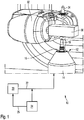
- a tool spindle 12 comprises a spindle motor 14 and a tool 18 clamped in a collet 16.
- FIG Fig. 1 is shown schematically.
- the control device 20 controls the spindle motor 14 so that a spindle current 22 flows through the spindle motor 14.
- the spindle current 22 is detected via a spindle load detection device 24. This has an output connection via which an output signal 26 is fed to the control device 20.
- This predetermined limit value 50 is set as a function of the machine and is higher in the case of a higher base current or no-load current of the spindle motor 14 and lower in the case of a lower base current or a lower no-load current.
- the limit value 50 is significantly lower than a breaking load of the tool 18, namely by an average of 25% in the example.
- the limit value 50 is changed and is during the greatest time of the machining progress between 10% and 80% of the machining, 30% below the breaking load of the tool 18, and, between 80% and 90% of the machining progress, 20% below the breaking load .
- the tool 18 serves to machine a workpiece 30.
- the workpiece 30 is held clamped in a robot arm 32.
- the robot arm 32 can be moved in 5 axes and also carries a reserve workpiece 34.
- the tool spindle 12 is stationary, so that the feed is carried out entirely via the robot arm 32. It goes without saying that a different axis distribution is also possible instead of 5/0, for example 3/2.
- the invention is also not intended to be restricted to rotary grinding; equivalent methods can also be used.
- the tool 18 is provided with a slightly different shape than the tool 34.
- the breaking load of the tool 18 is greater than the breaking load of the tool 34.
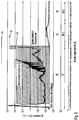
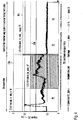
- Fig. 2 it can be seen how the spindle current 22 develops as machining progresses. The machining takes place in three steps when milling the anterior crown.
- the crown is pre-milled or rough milled.
- the crown is milled on the inside, with a significantly lower spindle current 22.
- the finish milling takes place in the third section 44; in this section the spindle current 22 is even lower.
- Each section is divided into a percentage processing progress between 0% and 100%.
- the spindle current 22 has a machine-dependent baseline of approximately 500 mAh.
- This spindle current 22 exists during the approach of the workpiece 30 to the tool 18. At approximately 4% of the processing progress of the section 40, the first contact between the workpiece 30 and the tool 18 occurs. The spindle current 22 increases considerably, to approximately 1.4 amperes.
- the spindle current 22 has dropped to values of around 0.6 amperes, and during rough milling it gradually increases a little.
- Fig. 2 two curves are shown, one is labeled “Abort by spindle load”, and the one labeled “Spindle load curve anterior crown”.
- the spindle current 22 increases significantly at approximately 60% of the machining progress in section 40. It rises above 1.3 amperes and then exceeds a limit value 50, which in the example was set at 1.36 amperes. As soon as this limit value 50 is reached, the milling process is aborted and a signal is emitted which indicates that the tool 18 must be replaced.
- spindle current 22 rises again significantly, to a value just below limit value 50. This is related to the increase in the wrap angle of workpiece 30.
- the limit value 50 is increased to a limit value 52 at approximately 95% of the processing progress. The spindle load remains below this limit value 52.
- This limit value 52 is also well below a breaking load 54.
- the spindle current 22 is significantly lower and does not exceed 0.6 amperes.
- a particular advantage of the invention is that the spindle current / breaking load monitoring prevents the workpiece 30 from being destroyed by the breakage of the tool 18.
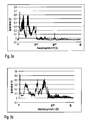
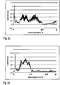
- FIG. 3a shows the spindle current 22 with an onlay
- Figure 3b with an inlay
- Figure 3c for a posterior crown
- Fig. 3d with a veneer.
- the spindle current 22 is dependent on the material of the dental restoration part, but of course also dependent on the tool 18 used.
- the spindle current 22 to be expected can be determined in advance and the limit value 44 can be set accordingly, it also being possible, as stated, to dynamically adapt the limit value 44.
- FIG Fig. 4 Another embodiment of a diagram according to the invention showing the spindle current 22 is shown in FIG Fig. 4 evident.
- the control according to Fig. 4 is characterized by a change in the limit values.
- the baseline or no-load current is just over 0.5 amps.
- the rough milling or rough turning grinding takes place in section 40.
- Spindle load monitoring is active in section 40, but not in sections 42 and 44.
- a cavity is milled in these sections, post-processing is carried out in section 42, and finishing is carried out in section 44.
- the limit value 50a of the spindle current 22, which must not be exceeded and applies in the entire section 40, is 2 amperes. This applies between 0 and 100% of the processing progress of section 40.
- a lower limit value 50b is switched on, with 1.25 amperes. This is barely reached at 62% of the processing progress; the maximum value there is 1.15 amperes.
- the limit value is increased to a limit value 50c, which is 1.6 amperes.
- This limit value 50c is switched on at 96% of the processing progress and applies up to 100%, i.e. until the end of section 40.
- the breaking load monitoring is then switched off.
- Fig. 5 shows how the spindle currents 22 differ in different machine tools.
- the machine tool labeled M1-166 has an no-load current of about 0.5 amps, while the no-load current of the machine tool labeled M1-175 is about 0.38 amps and is therefore significantly lower.
- the spindle load curve of the machine tool M1-166 is significantly higher than that of the machine tool M1-175, so that the limit value must also be adjusted accordingly.
- the spindle load curves were created by milling 5 anterior crowns each, whereby the individual curves are superimposed so that the overall curve is somewhat fuzzy, but which makes the difference between the machine tools clear.
Landscapes
- Engineering & Computer Science (AREA)
- Mechanical Engineering (AREA)
- Human Computer Interaction (AREA)
- Manufacturing & Machinery (AREA)
- Physics & Mathematics (AREA)
- General Physics & Mathematics (AREA)
- Automation & Control Theory (AREA)
- Constituent Portions Of Griding Lathes, Driving, Sensing And Control (AREA)
Priority Applications (2)
| Application Number | Priority Date | Filing Date | Title |
|---|---|---|---|
| EP19210905.6A EP3825058A1 (fr) | 2019-11-22 | 2019-11-22 | Machine-outil ainsi que procédé de fonctionnement d'une machine-outil |
| US16/950,235 US20210154798A1 (en) | 2019-11-22 | 2020-11-17 | Machine Tool And Method Of Operating A Machine Tool |
Applications Claiming Priority (1)
| Application Number | Priority Date | Filing Date | Title |
|---|---|---|---|
| EP19210905.6A EP3825058A1 (fr) | 2019-11-22 | 2019-11-22 | Machine-outil ainsi que procédé de fonctionnement d'une machine-outil |
Publications (1)
| Publication Number | Publication Date |
|---|---|
| EP3825058A1 true EP3825058A1 (fr) | 2021-05-26 |
Family
ID=68654372
Family Applications (1)
| Application Number | Title | Priority Date | Filing Date |
|---|---|---|---|
| EP19210905.6A Pending EP3825058A1 (fr) | 2019-11-22 | 2019-11-22 | Machine-outil ainsi que procédé de fonctionnement d'une machine-outil |
Country Status (2)
| Country | Link |
|---|---|
| US (1) | US20210154798A1 (fr) |
| EP (1) | EP3825058A1 (fr) |
Cited By (1)
| Publication number | Priority date | Publication date | Assignee | Title |
|---|---|---|---|---|
| CN112917242A (zh) * | 2021-02-07 | 2021-06-08 | 中国矿业大学 | 一种延长刀具寿命的切削方法 |
Families Citing this family (4)
| Publication number | Priority date | Publication date | Assignee | Title |
|---|---|---|---|---|
| JP7608142B2 (ja) * | 2020-12-16 | 2025-01-06 | Dgshape株式会社 | デンタル加工機のアラート通知装置、アラート通知システムおよびアラート通知用のコンピュータプログラム |
| CN113967823B (zh) * | 2021-11-30 | 2023-12-08 | 重庆宗申动力机械股份有限公司 | 一种带有不锈钢镶件的铝合金产品的制造方法 |
| EP4276549A1 (fr) * | 2022-05-10 | 2023-11-15 | Ivoclar Vivadent AG | Procédé d'usinage par enlèvement de copeaux permettant de fabriquer un objet dentaire |
| CN117773653A (zh) * | 2023-12-27 | 2024-03-29 | 创世纪工业装备(广东)有限公司 | 机床刀具的破损监控方法、装置及加工中心 |
Citations (6)
| Publication number | Priority date | Publication date | Assignee | Title |
|---|---|---|---|---|
| JPS62166948A (ja) * | 1986-01-16 | 1987-07-23 | Takaaki Nagao | 回転工具の異常予知装置 |
| JPH106170A (ja) * | 1996-06-17 | 1998-01-13 | Toyota Motor Corp | 工具管理方法および装置 |
| EP1449615A1 (fr) * | 2003-02-21 | 2004-08-25 | Fanuc Ltd | Unité de contrôle numérique pour la détection d'une charge anormale sur un moteur électrique |
| US20170357243A1 (en) * | 2016-06-09 | 2017-12-14 | Fanuc Corporation | Machine learning device, numerical control device and machine learning method for learning threshold value of detecting abnormal load |
| US20180181106A1 (en) * | 2016-12-28 | 2018-06-28 | Fanuc Corporation | Machine tool, production management system and method for estimating and detecting tool life |
| TWI662278B (zh) * | 2018-09-18 | 2019-06-11 | 財團法人工業技術研究院 | 刀具磨耗監控方法 |
Family Cites Families (4)
| Publication number | Priority date | Publication date | Assignee | Title |
|---|---|---|---|---|
| DE3111425A1 (de) * | 1980-03-27 | 1982-02-18 | Kabushiki Kaisha Komatsu Seisakusho, Tokyo | Verfahren und vorrichtung zur ermittlung abnormaler stoergroessen beim betrieb einer werkzeugmaschine |
| US4894644A (en) * | 1988-10-04 | 1990-01-16 | General Electric Company | Tool break/wear detection using a tracking minimum of detected vibrational signal |
| JP3256302B2 (ja) * | 1992-11-26 | 2002-02-12 | 株式会社日平トヤマ | 加工機の工具破損防止装置 |
| US20150127139A1 (en) * | 2013-11-07 | 2015-05-07 | The Boeing Company | Real-Time Numerical Control Tool Path Adaptation Using Force Feedback |
-
2019
- 2019-11-22 EP EP19210905.6A patent/EP3825058A1/fr active Pending
-
2020
- 2020-11-17 US US16/950,235 patent/US20210154798A1/en not_active Abandoned
Patent Citations (7)
| Publication number | Priority date | Publication date | Assignee | Title |
|---|---|---|---|---|
| JPS62166948A (ja) * | 1986-01-16 | 1987-07-23 | Takaaki Nagao | 回転工具の異常予知装置 |
| JPH106170A (ja) * | 1996-06-17 | 1998-01-13 | Toyota Motor Corp | 工具管理方法および装置 |
| EP1449615A1 (fr) * | 2003-02-21 | 2004-08-25 | Fanuc Ltd | Unité de contrôle numérique pour la détection d'une charge anormale sur un moteur électrique |
| US20170357243A1 (en) * | 2016-06-09 | 2017-12-14 | Fanuc Corporation | Machine learning device, numerical control device and machine learning method for learning threshold value of detecting abnormal load |
| US20180181106A1 (en) * | 2016-12-28 | 2018-06-28 | Fanuc Corporation | Machine tool, production management system and method for estimating and detecting tool life |
| TWI662278B (zh) * | 2018-09-18 | 2019-06-11 | 財團法人工業技術研究院 | 刀具磨耗監控方法 |
| US20200089191A1 (en) * | 2018-09-18 | 2020-03-19 | Industrial Technology Research Institute | Method for monitoring cutting-tool abrasion |
Cited By (1)
| Publication number | Priority date | Publication date | Assignee | Title |
|---|---|---|---|---|
| CN112917242A (zh) * | 2021-02-07 | 2021-06-08 | 中国矿业大学 | 一种延长刀具寿命的切削方法 |
Also Published As
| Publication number | Publication date |
|---|---|
| US20210154798A1 (en) | 2021-05-27 |
Similar Documents
| Publication | Publication Date | Title |
|---|---|---|
| EP3825058A1 (fr) | Machine-outil ainsi que procédé de fonctionnement d'une machine-outil | |
| DE102009007437B4 (de) | Reitstock-Regelungsvorrichtung | |
| EP0228007B1 (fr) | Machine-outil et son mode d'action | |
| EP1066801B1 (fr) | Procédé et dispositif pour fabriquer des prothèses médicales en particulier dentaires | |
| DE2758275A1 (de) | Maschine und verfahren zum schleifen von rotationsflaechen | |
| EP3332737B1 (fr) | Procédé de production d'une partie de restauration dentaire et machine d'usinage dentaire | |
| EP3271111A1 (fr) | Procédé servant à rectifier des pièces à usiner comportant des rainures et rectifieuse | |
| DE3411113A1 (de) | Verfahren zum bestimmen der abnutzung von werkzeugen | |
| DE4021090C2 (de) | Bearbeitungsvorrichtung mit Mitteln zur Änderung der radialen Position von Schneidwerkzeugen | |
| EP1019219B1 (fr) | Dispositif de mesure sur une machine destinee a l'usinage de pieces avec des dents coupantes, notamment des lames de scie | |
| DE102012111355A1 (de) | Flüssigkeitsausstoßvorrichtung | |
| EP0803325B1 (fr) | Procédé pour le meulage façonné du bord de circonférence de verres de lunettes et le cas échéant meulage de facette suivant ainsi que dispositif de meulage pour les bords de verres de lunettes | |
| EP3707488A1 (fr) | Procédé et dispositif d'équilibrage | |
| EP1425475A1 (fr) | Dispositif de decoupe de sol | |
| EP1409186B1 (fr) | Dispositif d'erosion comprenant une tete d'erosion concue pour eliminer des elements de connexion metalliques | |
| EP3873697B1 (fr) | Dispositif de freinage de sécurité doté de deux paliers de freinage | |
| EP1447729A2 (fr) | Méthode de commande d'orientation d'une broche | |
| EP3363598B1 (fr) | Procédé permettant de faire ralentir une broche porte-outil | |
| WO2022090304A1 (fr) | Procédé de commande et/ou de surveillance d'un processus d'usinage de pièces | |
| DE3618349A1 (de) | Verfahren und einrichtung zur ueberpruefung eines abstechvorgangs | |
| DE2030851A1 (de) | Schleifmaschine | |
| DE102021132300B3 (de) | Verfahren zum Betreiben einer Werkzeugmaschine mit Achsüberwachung und Werkzeugmaschine eingerichtet zur Durchführung des Verfahrens | |
| EP2301714B1 (fr) | Rectifieuse plane et procédé de fonctionnement et/ou d'entretien d'une rectifieuse plane | |
| DE3546252A1 (de) | Werkzeugmaschine und deren betriebsverfahren | |
| EP1475185B1 (fr) | Méthode et dispositif pour abraser des pièces à symétrie de révolution |
Legal Events
| Date | Code | Title | Description |
|---|---|---|---|
| PUAI | Public reference made under article 153(3) epc to a published international application that has entered the european phase |
Free format text: ORIGINAL CODE: 0009012 |
|
| STAA | Information on the status of an ep patent application or granted ep patent |
Free format text: STATUS: THE APPLICATION HAS BEEN PUBLISHED |
|
| AK | Designated contracting states |
Kind code of ref document: A1 Designated state(s): AL AT BE BG CH CY CZ DE DK EE ES FI FR GB GR HR HU IE IS IT LI LT LU LV MC MK MT NL NO PL PT RO RS SE SI SK SM TR |
|
| STAA | Information on the status of an ep patent application or granted ep patent |
Free format text: STATUS: REQUEST FOR EXAMINATION WAS MADE |
|
| 17P | Request for examination filed |
Effective date: 20211126 |
|
| RBV | Designated contracting states (corrected) |
Designated state(s): AL AT BE BG CH CY CZ DE DK EE ES FI FR GB GR HR HU IE IS IT LI LT LU LV MC MK MT NL NO PL PT RO RS SE SI SK SM TR |
|
| STAA | Information on the status of an ep patent application or granted ep patent |
Free format text: STATUS: EXAMINATION IS IN PROGRESS |
|
| 17Q | First examination report despatched |
Effective date: 20230908 |