EP3825189A1 - Diebstahlwarnsystem und diebstahlwarnverfahren - Google Patents
Diebstahlwarnsystem und diebstahlwarnverfahren Download PDFInfo
- Publication number
- EP3825189A1 EP3825189A1 EP20208668.2A EP20208668A EP3825189A1 EP 3825189 A1 EP3825189 A1 EP 3825189A1 EP 20208668 A EP20208668 A EP 20208668A EP 3825189 A1 EP3825189 A1 EP 3825189A1
- Authority
- EP
- European Patent Office
- Prior art keywords
- vehicle
- position information
- terminals
- theft
- user
- Prior art date
- Legal status (The legal status is an assumption and is not a legal conclusion. Google has not performed a legal analysis and makes no representation as to the accuracy of the status listed.)
- Granted
Links
Images


Classifications
-
- B—PERFORMING OPERATIONS; TRANSPORTING
- B60—VEHICLES IN GENERAL
- B60R—VEHICLES, VEHICLE FITTINGS, OR VEHICLE PARTS, NOT OTHERWISE PROVIDED FOR
- B60R25/00—Fittings or systems for preventing or indicating unauthorised use or theft of vehicles
- B60R25/30—Detection related to theft or to other events relevant to anti-theft systems
-
- B—PERFORMING OPERATIONS; TRANSPORTING
- B60—VEHICLES IN GENERAL
- B60R—VEHICLES, VEHICLE FITTINGS, OR VEHICLE PARTS, NOT OTHERWISE PROVIDED FOR
- B60R25/00—Fittings or systems for preventing or indicating unauthorised use or theft of vehicles
- B60R25/10—Fittings or systems for preventing or indicating unauthorised use or theft of vehicles actuating a signalling device
- B60R25/1004—Alarm systems characterised by the type of sensor, e.g. current sensing means
- B60R25/1012—Zone surveillance means, e.g. parking lots, truck depots
-
- B—PERFORMING OPERATIONS; TRANSPORTING
- B60—VEHICLES IN GENERAL
- B60R—VEHICLES, VEHICLE FITTINGS, OR VEHICLE PARTS, NOT OTHERWISE PROVIDED FOR
- B60R25/00—Fittings or systems for preventing or indicating unauthorised use or theft of vehicles
- B60R25/10—Fittings or systems for preventing or indicating unauthorised use or theft of vehicles actuating a signalling device
- B60R25/102—Fittings or systems for preventing or indicating unauthorised use or theft of vehicles actuating a signalling device a signal being sent to a remote location, e.g. a radio signal being transmitted to a police station, a security company or the owner
-
- B—PERFORMING OPERATIONS; TRANSPORTING
- B60—VEHICLES IN GENERAL
- B60R—VEHICLES, VEHICLE FITTINGS, OR VEHICLE PARTS, NOT OTHERWISE PROVIDED FOR
- B60R25/00—Fittings or systems for preventing or indicating unauthorised use or theft of vehicles
- B60R25/30—Detection related to theft or to other events relevant to anti-theft systems
- B60R25/33—Detection related to theft or to other events relevant to anti-theft systems of global position, e.g. by providing GPS coordinates
Definitions
- the invention relates to an anti-theft alarm system and anti-theft alarm methods which use position information of a vehicle and a user of the vehicle to identify the theft of the vehicle at an early stage.
- anti-theft alarm systems which are attached to vehicles and generate an acoustic warning signal in the event of a possible theft.
- the acoustic warning signal can only be perceived by a corresponding vehicle owner in a certain area. It can happen that despite the warning signal, the vehicle owner does not notice a theft (attempt). The police only find out about the theft (attempt) if they are notified by a person who has heard the acoustic warning signal.
- a vehicle-mounted anti-theft alarm system can be put out of operation by vehicle manipulation.
- the EP 2 048 046 B1 describes a vehicle control system having a control section and a storage section.
- the storage section automatically generates and stores behavior pattern information of a user of the vehicle.
- This control section controls an in-vehicle device installed in a vehicle in accordance with and in accordance with a positional relationship between a current position of a mobile terminal received by a receiving portion installed in the vehicle and a current position of the vehicle detected by a vehicle position detection portion with the behavior pattern information.
- a method for determining theft of a vehicle belonging to a vehicle fleet is known.
- a current position of the driver is determined on the basis of a mobile terminal of a driver of the vehicle.
- a theft is suspected if, on the basis of a comparison of a current position of the vehicle with a position planned in time, a deviation is determined which exceeds a predetermined distance value, with a position of the driver in relation to the vehicle exceeding a further predetermined distance value. If theft is suspected, a theft notification is issued.
- a vehicle-side terminal locates a current position of a vehicle and sends early warning information, which includes the position information, to a server. The forwards the early warning information to a portable terminal.
- a current position of the portable terminal is recorded in the background of the portable device.
- the object of the present invention is to provide an improved theft warning system and an improved theft warning method.
- a current location of the vehicle can be determined from the position information of the vehicle.
- the vehicle has a corresponding (location) detection device, such as a GPS system, for detecting the current location of the vehicle.
- a movement and thus also a speed of the vehicle can also be recorded / determined from the position information of the vehicle.
- Mobile terminals such as smartphones, tablets, mobile computers (laptops), portable devices (wearables), have (location) detection devices.
- a current location of a mobile terminal can be recorded by at least one of WLAN-based positioning and GSM positioning.
- a (current) location of a desktop PC can also be recorded using suitable methods.
- movement information such as direction and speed
- direction information for the vehicle and the terminals can be derived from the position information of the vehicle and the terminals.
- the present disclosure is not restricted to a specific (location) method for detecting the locations of the terminals and the vehicle, as described here.
- Other known location methods for terminals and vehicles are also possible.
- the circuitry of the anti-theft alarm system is set up to carry out the above steps.
- the circuit arrangement is designed accordingly for this purpose.
- the circuit arrangement can include appropriate means, e.g. a communication unit for sending and receiving data, a computer unit for comparing the position information, a signal generating unit, etc.
- these means can also include servers that are in particular in the back end, i.e. not in the vehicle.
- the theft alarm system generates the warning signal when the vehicle leaves predetermined areas, each predetermined area (of the plurality of predetermined areas) of position information of a corresponding terminal from the plurality of terminals is dependent.
- this can mean that the vehicle is moving out of one of the predetermined areas.
- the vehicle travels at a predetermined (minimum) speed out of one of the predetermined areas. This ensures that no alarm is generated when the vehicle is parked.
- Each of the predetermined areas is dependent, for example, on a current location of a corresponding terminal.
- Each terminal from the plurality of terminals is associated with the user of the vehicle.
- it is end devices that belong to the user.
- they can also be terminals belonging to people associated with the user, such as family members, friends, work colleagues, acquaintances, etc.
- the vehicle It is also possible for the vehicle to have several users.
- the user of a vehicle can be the owner, vehicle keeper, renter, etc. of the vehicle. In other words, the user is authorized to use the car in advance.
- the warning signal When the vehicle leaves one of the predetermined areas, the warning signal is generated.
- the warning signal therefore indicates that theft is suspected.
- the predetermined areas are dependent on the position information of the plurality of terminal devices (associated with the user), it can be determined more reliably whether the vehicle is being stolen. So it can happen that a user forgets their smartphone on the way to work at home, but wears a wearable (e.g. smartwatch). This can reduce the number of false alarms caused by the anti-theft alarm system. At the same time, however, theft can be detected comparatively early by automatically detecting when the vehicle leaves one of the predetermined areas.
- the theft warning system is arranged outside the vehicle, for example in the form of a server in the back end, the theft warning system has a lower risk of manipulation.
- the anti-theft alarm system can also be present on the vehicle.
- no warning signal is generated if the vehicle leaves the predetermined area, but a direction of movement and a speed of the vehicle with a direction of movement and a speed of one of the terminals of the plurality of Terminals essentially match. This means that inaccuracies in the recorded and retrieved position information of the vehicle and the end devices can be included.
- a warning signal should also be generated if one of the terminals in the vehicle is forgotten and the vehicle is stolen.
- a move away / removal of the user from the vehicle is automatically recognized if at least one of the terminal devices assigned to him moves away from the vehicle and at the same time another device assigned to the same user remains at the position of the vehicle.
- the device remaining in the vehicle is temporarily removed from the list of safe devices.
- the user of the vehicle can manually remove the forgotten terminal from the plurality of terminal devices associated with the user.
- this multitude of end devices can be stored in a database that can be processed by the user via a corresponding service, e.g. an app or web application.
- the user can be notified via one of the end devices associated with him.
- a corresponding notification is sent to the corresponding end device.
- the notification can, for example, be at least one of a message (SMS, text message, email, etc.), an automated call, and the like.
- SMS short message
- text message email
- automated call and the like.
- the notification is sent to all of the terminal devices associated with the user, it can be ensured that the user or the persons associated with him are informed of the suspected theft.
- the anti-theft function can, for example, be the triggering of an alarm signal from the vehicle. In this way, passers-by can be made aware of the theft of the vehicle.
- the anti-theft function can put the vehicle into a predetermined vehicle mode in which only a limited driving speed is possible.
- the predetermined vehicle operation can prevent a restart after the vehicle has stopped. This prevents the stolen vehicle from moving too far (from the end devices).
- the authorization request can be sent to one of the user's end devices.
- these terminals can be set up to receive the authorization request through an app or notification, e.g. SMS.
- the authorization signal is sent.
- the authorization signal enables an authorized journey, i.e. there is no theft of the vehicle.
- the response to the authorization request is negative, that is, if the user does not approve the trip, the anti-theft signal is sent that triggers the anti-theft function on the vehicle side.
- the anti-theft signal can therefore correspond to the warning signal above.
- a voice connection to the vehicle can be established using appropriate means in the vehicle so that the user can contact the current driver. This can be done, for example, in such a way that a terminal of the user receiving the authorization request establishes the voice connection to the vehicle. If an observation camera is installed in the interior of the vehicle, it is also possible for the user to establish a connection to the observation camera via one of his end devices, in particular the end device receiving the authorization request. With these additional options, the user can determine for himself whether the current driver is authorized for the current vehicle use. The user can subsequently take the current driver to the ride authorize or have one of the other anti-theft functions (described above) carried out.
- the theft protection signal can also be sent accordingly.
- the user whose vehicle is leaving the predetermined areas can decide whether a journey of the vehicle without his presence is authorized. This reduces the number of false positives.
- the position information of the plurality of terminals may include at least one of past locations and current locations of the plurality of terminals.
- a location history of the end devices can thus be determined so that probable whereabouts of the user can be derived.
- the predetermined locations can then be dependent on the probable locations of the user / the terminals. This means that the anti-theft alarm system can be customized.
- the predetermined areas may further be at least one of time, day, and location dependent.
- the shape and / or size of the predetermined areas are thereby variable. For example, if the predetermined area is a circular area, a radius of the circle may be larger or smaller depending on the time, day and / or location.
- the position information of the vehicle and the position information of the plurality of terminals can be received and compared at predetermined time intervals.
- the predetermined time intervals can in particular be at least one of time, day and location-dependent. In this way, a probability of theft, which in turn depends on the time, day and place, can be taken into account. If a probability of theft is lower, the predetermined time interval can be higher, so that the theft system has to use less computing power.
- the predetermined areas can be parts of a total area and the total area can be dependent on the position information of the plurality of terminals.
- two end devices can be in two different locations.
- the two (dependent on these two terminals) predetermined areas can are not overlapping.
- a further predetermined area for example in the form of a corridor, can connect the two predetermined areas with one another.
- the further predetermined area is therefore a connecting section.
- the corridor and the two predetermined areas then form the total area in which the vehicle may be without a theft alarm being triggered. As a result, a crossing of the vehicle from one terminal device location to another terminal device location is not suspected of being theft.
- the terminals of the plurality of terminals may be one of a portable device (wearables), a mobile terminal, and a desktop computer.
- a vehicle 1 that has a (not shown) location detection device. Position information, including a current location, of vehicle 1 is determined by means of the location detection device.
- the vehicle also has communication means (not shown) in order to communicate with an anti-theft alarm system 5. So is the position information of the vehicle can be transmitted to the theft alarm system 5.
- the anti-theft alarm system 5 is arranged in a backend and can, for example, be a server.
- FIG 1 a plurality of terminals 3a, 3b shown. It goes without saying that the plurality of terminals can also have more than the two illustrated terminals 3a, 3b.
- the multiplicity of terminals 3 a, 3 b is associated with a user of the vehicle 1. This association information can be stored in the theft warning system 5, in particular in a database (not shown).
- Position information of each of the terminals 3a, 3b can be detected, for example, via (not shown) terminal-side location detection device and transmitted to the theft warning system 5 via (not shown) terminal-side communication means.
- the theft warning system 5 can locate each of the terminals 3a, 3b by means of known locating methods.
- the anti-theft alarm system 5 has a circuit arrangement which is designed and set up to receive and compare the position information of the vehicle 1 and the position information of the plurality of terminals 3a, 3b, among other things. Furthermore, the switching arrangement is designed and set up, based on the comparison of the position information of the vehicle 1 and the plurality of terminals 3a, 3b, to determine whether the vehicle 1 is leaving a predetermined range from a plurality of predetermined ranges 9a, 9b, 9c.
- the plurality of predetermined areas 9a, 9b, 9c are shown in FIG Figure 3 shown. Each predetermined area 9a, 9b, 9c is dependent on position information of a corresponding terminal from the plurality of terminals 3a, 3b.
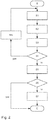
- FIG. 2 an anti-theft alarm system is shown. The method can be carried out, for example, by the theft alarm system 5.
- step S1 the position information of the vehicle 1 is received and / or retrieved.
- step S2 the position information of the plurality of terminals 3a, 3b is received and / or retrieved. Steps S1 and S2 can also be swapped.
- step S3 the plurality of predetermined areas 9a, 9b, 9c in which the vehicle 1 is allowed to be located is called up.
- the position information of the vehicle 1 and the A large number of terminals 3a, 3b and the large number of predetermined areas 9a, 9b, 9c can be deposited / stored in the database of the anti-theft alarm system 5.
- the plurality of predetermined areas 9a, 9b, 9c is dependent on the position information of the plurality of terminals 3a, 3b.
- step S4 it is checked whether the vehicle 1 is located in one of the predetermined areas 9a, 9b, 9c. If so, the process continues to step S4a.
- step S4a a predetermined time is awaited before the method continues with step S1.
- the predetermined time is arbitrary and can in particular be at least several minutes.
- step S4 If the test in step S4 shows that the vehicle 1 is leaving one of the predetermined areas 9a, 9b, 9c, a warning signal is generated.
- the warning signal can only be generated when the check steps S1 to S4 are carried out several times in succession and it results that the vehicle 1 is leaving one of the predetermined areas 9a, 9b, 9c. The susceptibility of the theft system 5 to errors can thus be reduced.
- an authorization request is sent to the user of the vehicle 1 in step S5.
- the authorization request asks whether the user would like to allow the current driver of the vehicle 1 to drive (outside of the predetermined areas 9a, 9b, 9c).
- the authorization request can be sent to all users in step S5.
- a voice connection can be set up in vehicle 1 using appropriate means in vehicle 1 in order to contact the current driver. It is also possible, if an observation camera is installed in the interior of the vehicle 1, to establish a connection to it.
- Step S5 is optional and the method can jump straight to step S6 after step S4.
- step S6 the user's response to the authorization request is received and evaluated. If there is an authorization by the user of the vehicle 1, that is, it has been approved the user stops the trip, the anti-theft alarm procedure is ended. An authorization signal is sent to a control unit (not shown) of vehicle 1, which triggers an authorized drive function on the vehicle. The current driver is therefore allowed to use the vehicle 1 up to a predetermined event or for a predetermined duration.
- the predetermined event can, for example, be the parking of the vehicle, in particular at a predetermined location. In the event that there are several users for the vehicle 1, the approval of one of the several users can also be sufficient.
- step S6 If it is determined in step S6 that there is no authorization, a theft protection signal is sent to the control unit (not shown) of vehicle 1, so that in step S7 an anti-theft function on the vehicle is carried out.
- the warning signal generated in step S4 can be sent to the vehicle control unit so that step S7 is also carried out in response to the warning signal, which indicates that the vehicle is leaving one of the predetermined areas 9a, 9b, 9c.
- a map view 11 is shown by way of example and schematically, which shows an overall area 9 in which the vehicle 1 can be located without theft being suspected.
- predetermined areas 9a and 9b are shown which correspond to a zone around the terminals 3a and 3b, respectively. When the terminals 3a and 3b move, the predetermined areas 9a and 9b move accordingly.
- the predetermined areas 9a and 9b are here circular or octagonal. These shapes are only exemplary and can be adapted as required.
- the predetermined areas 9a, 9b, in particular their shape, can thus have a multiplicity of shapes. In particular, the predetermined areas can also be dependent on the day, time and location or can also be adapted to be user-specific.
- the overall area 9 can furthermore have a connecting section 9c which connects the two predetermined areas 9a, 9b to one another.
- the connecting section 9c is thus a corridor which has corresponding driving routes which lead the vehicle 1 from one of the terminals 3a, 3b to the other. If the vehicle 1 is in the corridor 9c, it is assumed that the vehicle 1 is only on a crossing from one of the terminals 3a, 3b to the other. Accordingly, no theft will be accepted.
- the predetermined areas 9a, 9b and the connecting section 9c form the total area 9.
- the total area 9, in particular the predetermined areas 9a, 9b and the connecting section 9c form an imaginary boundary on the surface of the earth (or in the air).
Landscapes
- Engineering & Computer Science (AREA)
- Mechanical Engineering (AREA)
- Transportation (AREA)
- Radar, Positioning & Navigation (AREA)
- Remote Sensing (AREA)
- Burglar Alarm Systems (AREA)
- Alarm Systems (AREA)
Abstract
Description
- Die Erfindung betrifft ein Diebstahlwarnsystem und Diebstahlwarnverfahren, die mittels Positionsinformationen eines Fahrzeugs und eines Nutzers des Fahrzeugs frühzeitig einen Diebstahl des Fahrzeugs erkennen.
- Bisher sind Diebstahlwarnanlagen bekannt, die an Fahrzeugen angebracht sind und bei einem möglichen Diebstahl ein akustisches Warnsignal erzeugen. Das akustische Warnsignal ist nur in einem bestimmten Umkreis für einen entsprechenden Fahrzeughalter wahrnehmbar. So kann es vorkommen, dass trotz Warnsignal der Fahrzeughalter einen Diebstahl(-versuch) nicht bemerkt. Auch erfährt die Polizei von dem Diebstahl(-versuch) nur, wenn sie durch eine das akustische Warnsignal wahrnehmende Person benachrichtigt wird. Ferner kann eine derartige fahrzeugseitige Diebstahlwarnanlage durch Fahrzeugmanipulation außer Betrieb gesetzt werden.
- Aus der
US 2017/0136947 A1 sind ein Frühwarn-Verfahren, System und Server bekannt, die auf einer Satellitenortung basieren. Es werden Abstände zwischen einem Beobachter, einem beobachteten Objekt und einem Fahrzeug berechnet. Wenn sich das Fahrzeug mit einer bestimmten Geschwindigkeit bewegt, sich ein Abstand zwischen dem Beobachter und dem beobachteten Objekt innerhalb eines vorbestimmten Kurzabstands befindet und sich ein Abstand zwischen dem Fahrzeug und dem Beobachter sowie dem beobachteten Objekt vergrößert, kann festgestellt werden, dass das Fahrzeug gestohlen sein könnte. Dann wird eine Alarminformation an ein Beobachter-Endgerät gesendet. - Die
EP 2 048 046 B1 beschreibt ein Fahrzeugsteuerungssystem mit einem Steuerabschnitt und einem Speicherabschnitt. Der Speicherabschnitt erzeugt und speichert automatisch Verhaltensmusterinformationen eines Nutzers des Fahrzeugs. Dieser Steuerabschnitt steuert eine in einem Fahrzeug installierte Fahrzeugvorrichtung in Übereinstimmung mit einer Positionsbeziehung zwischen einer gegenwärtigen Position eines mobilen Terminals, die durch einen in dem Fahrzeug installierten Empfangsabschnitt empfangen wird, und einem gegenwärtigen Standort des Fahrzeugs, der durch einen Fahrzeugstandortdetektionsabschnitt detektiert wird, und in Übereinstimmung mit den Verhaltensmusterinformationen. - Aus der
DE 10 2018 002 327 A1 ist ein Verfahren zur Ermittlung eines Diebstahls eines zu einer Fahrzeugflotte gehörenden Fahrzeuges bekannt. Hierbei wird anhand eines mobilen Endgeräts eines Fahrers des Fahrzeugs eine momentane Position des Fahrers ermittelt. Es wird ein Diebstahl vermutet, wenn anhand eines Vergleiches einer momentanen Position des Fahrzeugs mit einer zeitlich geplanten Position eine Abweichung ermittelt wird, die einen vorgegebenen Entfernungswert überschreitet, wobei eine Position des Fahrers zu dem Fahrzeug einen weiteren vorgegebenen Entfernungswert überschreitet. Bei vermutetem Diebstahl wird eine Diebstahlbenachrichtigung ausgegeben. - In der
CN 104 192 094 A wird ein Anti-Diebstahlverfahren beschrieben. Ein fahrzeugseitiges Endgerät lokalisiert eine momentane Position eines Fahrzeugs und sendet eine Frühwarninformation, die die Positionsinformation umfasst, an einen Server. Der leitet die Frühwarninformation an ein tragbares Endgerät. Im Hintergrund des tragbaren Geräts wird eine momentane Position des tragbaren Endgeräts erfasst. Wenn eine momentane Position des tragbaren Endgeräts und die Positionsinformation des fahrzeugseitigen Endgeräts nicht konsistent sind und sich die Positionsinformation des fahrzeugseitigen Endgeräts ändert, gibt das tragbare Endgerät einen Alarm aus. - Aufgabe der vorliegenden Erfindung ist es, ein verbessertes Diebstahlwarnsystem und ein verbessertes Diebstahlwarnverfahren bereitzustellen.
- Diese Aufgabe wird durch ein Diebstahlwarnsystem nach Anspruch 1 und ein Verfahren nach Anspruch 10 gelöst.
- Weitere vorteilhafte Ausgestaltungen der Erfindung ergeben sich aus den Unteransprüchen und der folgenden Beschreibung bevorzugter Ausführungsbeispiele der vorliegenden Erfindung.
- Ein erster Aspekt der Offenbarung betrifft ein Diebstahlwarnsystem zum Auswerten von Positionsinformationen eines Fahrzeugs und Positionsinformationen einer Vielzahl von Endgeräten, die mit einem Nutzer des Fahrzeugs assoziiert sind. Das Diebstahlwarnsystem weist eine Schaltungsanordnung auf, die eingerichtet ist zum:
- Empfangen der Positionsinformationen des Fahrzeugs und der Positionsinformationen der Vielzahl von Endgeräten;
- Vergleichen der Positionsinformationen des Fahrzeugs und der Positionsinformationen der Vielzahl von Endgeräten; und
- Erzeugen eines Warnsignals, wenn das Fahrzeug einen vorbestimmten Bereich aus einer Vielzahl von vorbestimmten Bereichen verlässt, wobei jeder vorbestimmte Bereich von einer Positionsinformation eines entsprechenden Endgeräts aus der Vielzahl von Endgeräten abhängig ist.
- Aus den Positionsinformationen des Fahrzeugs ist ein momentaner Standort des Fahrzeugs ermittelbar. So weist das Fahrzeug entsprechende (Standort-)Erfassungseinrichtung, wie bspw. ein GPS-System, für eine Erfassung des momentanen Standorts des Fahrzeugs auf. Aus den Positionsinformationen des Fahrzeugs kann auch eine Bewegung und somit auch eine Geschwindigkeit des Fahrzeugs erfasst/ermittelt werden.
- Entsprechendes gilt auch für die Erfassung von Positionsinformationen der Vielzahl von Endgeräten. So weisen mobile Endgeräte, wie Smartphone, Tablets, mobile Computer (Laptops), tragbare Vorrichtungen (Wearables), (Standort-) Erfassungseinrichtungen auf. Alternativ oder ergänzend kann ein momentaner Standort eines mobilen Endgeräts durch mindestens eines von WLAN-basierter Ortung und GSM-Ortung erfasst werden. Aber auch ein (momentaner) Standort eines Desktop-PCs lässt sich mittels geeigneter Verfahren erfassen.
- Ferner sind aus den Positionsinformationen des Fahrzeugs und der Endgeräte Bewegungsinformationen, wie Richtung und Geschwindigkeit, für das Fahrzeug und die Endgeräte ableitbar.
- Die vorliegende Offenbarung ist nicht auf ein bestimmtes und auf die hier beschriebenen (Ortungs-)Verfahren zur Erfassung der Standorte der Endgeräte und des Fahrzeugs beschränkt. Es sind auch andere bekannte Ortungsverfahren für Endgeräte als auch Fahrzeuge möglich.
- Die Schaltungsanordnung des Diebstahlwarnsystems ist eingerichtet, die obigen Schritte auszuführen. Dafür ist die Schaltungsanordnung entsprechend ausgebildet. So kann die Schaltungsanordnung entsprechende Mittel, z.B. eine Kommunikationseinheit zum Senden und Empfangen von Daten, eine Rechnereinheit zum Vergleichen der Positionsinformationen, eine Signalerzeugungseinheit, etc. Ferner können diese Mittel auch Server umfassen, die insbesondere im Backend vorliegen, also nicht im Fahrzeug.
- Das Diebstahlwarnsystem erzeugt das Warnsignal, wenn das Fahrzeug vorbestimmte Bereiche verlässt, wobei jeder vorbestimmte Bereich (der Vielzahl von vorbestimmten Bereichen) von einer Positionsinformation eines entsprechenden Endgeräts aus der Vielzahl von Endgeräten abhängig ist. Insbesondere kann das bedeuten, dass sich das Fahrzeug aus einem der vorbestimmten Bereiche herausbewegt. Mit anderen Worten, das Fahrzeug fährt mit einer vorbestimmten (Mindest-)Geschwindigkeit aus einem der vorbestimmten Bereiche. Damit kann sichergestellt werden, dass kein Alarm erzeugt wird, wenn das Fahrzeug parkt.
- Jeder der vorbestimmten Bereiche ist bspw. von einem momentanen Standort eines entsprechenden Endgeräts abhängig.
- Jedes Endgerät aus der Vielzahl von Endgeräten ist mit dem Nutzer des Fahrzeugs assoziiert. In der Regel sind es Endgeräte, die dem Nutzer gehören. Es können aber auch Endgeräte von mit dem Nutzer assoziierten Personen sein, wie bspw. Familienangehörige, Freunde, Arbeitskollegen, Bekannte, etc. Es ist auch möglich, dass das Fahrzeug mehrere Nutzer aufweist. Der Nutzer eines Fahrzeugs kann der Eigentümer, Fahrzeughalter, Mieter, etc. des Fahrzeugs sein. Mit anderen Worten, der Nutzer ist von vornherein berechtigt, das Auto zu benutzen.
- Wenn das Fahrzeug einen der vorbestimmten Bereiche verlässt, wird das Warnsignal erzeugt. Das Warnsignal gibt also an, dass ein Diebstahl vermutet wird.
- Indem die vorbestimmten Bereiche von den Positionsinformationen der Vielzahl von (mit dem Nutzer assoziierten) Endgeräten abhängig sind, ist zuverlässiger feststellbar, ob das Fahrzeug gestohlen wird. So kann es durchaus vorkommen, dass ein Nutzer sein Smartphone auf dem Weg in die Arbeit zuhause vergisst, aber ein Wearable (z.B. Smartwatch) trägt. Dadurch kann die Anzahl der Fehlalarme durch das Diebstahlwarnsystem reduziert werden. Gleichzeitig kann aber ein Diebstahl vergleichsweise früh erkannt werden, indem automatisch erkannt wird, wenn das Fahrzeug einen der vorbestimmten Bereiche verlässt.
- Insbesondere wenn das Diebstahlwarnsystem außerhalb des Fahrzeugs angeordnet ist, beispielsweise im Backend als Server ausgebildet ist, weist das Diebstahlwarnsystem ein geringeres Manipulationsrisiko auf. Alternativ kann das Diebstahlwarnsystem auch fahrzeugseitig vorliegen.
- In einer Alternative wird kein Warnsignal erzeugt, wenn das Fahrzeug zwar den vorbestimmten Bereich verlässt, aber eine Bewegungsrichtung und eine Geschwindigkeit des Fahrzeugs mit einer Bewegungsrichtung und einer Geschwindigkeit eines der Endgeräte der Vielzahl von Endgeräten im Wesentlichen übereinstimmt. Somit können Ungenauigkeiten in den erfassten und abgerufenen Positionsinformationen des Fahrzeugs und der Endgeräte miteinbezogen werden.
- In einer weiteren Alternative soll ferner ein Warnsignal erzeugt werden, wenn eines der Endgeräte in dem Fahrzeug vergessen wird und das Fahrzeug gestohlen wird. Dafür wird ein Wegbewegen/Entfernen des Nutzers vom Fahrzeug automatisch erkannt, wenn sich mindestens eines der ihm zugeordneten Endgeräte vom Fahrzeug örtlich wegbewegt und gleichzeitig ein anderes, demselben Nutzer zugeordnetes Gerät an der Position des Fahrzeuges verbleibt. In diesem Fall, wird das im Fahrzeug verbleibende Gerät temporär aus der Liste der sicheren Geräte entfernt. Alternativ kann der Nutzer des Fahrzeugs das vergessene Endgerät aus der Vielzahl von den mit dem Nutzer assoziierten Endgeräten manuell entfernen. Beispielsweise kann diese Vielzahl von Endgeräten in einer Datenbank hinterlegt sein, die durch den Nutzer über einen entsprechenden Service, z.B. App oder Webapplikation, bearbeitbar ist.
- Ferner kann, wenn das Warnsignal vorliegt, die Schaltungsanordnung eingerichtet sein zum:
- Benachrichtigen des Nutzers des Fahrzeugs.
- Dabei kann der Nutzer über eines der mit ihm assoziierten Endgeräte benachrichtigt werden. Eine entsprechende Benachrichtigung wird an das entsprechende Endgerät gesendet. Die Benachrichtigung kann bspw. mindestens eines von einer Meldung (SMS, Textnachricht, Email, etc.), einem automatisierten Anruf und ähnliches sein. Insbesondere wenn die Benachrichtigung an alle mit dem Nutzer assoziierten Endgeräte gesendet wird, kann sichergestellt werden, dass der Nutzer oder die mit ihm assoziierten Personen über den vermuteten Diebstahl unterrichtet werden.
- In einer Alternative kann die Schaltungsanordnung ferner eingerichtet sein zum:
- Senden des Warnsignals an ein Steuergerät des Fahrzeugs, um fahrzeugseitig eine Diebstahlschutzfunktion auszulösen.
- Die Diebstahlschutzfunktion kann bspw. das Auslösen eines fahrzeugseitigen Alarmsignals sein. Dadurch können Passanten auf den vorliegenden Diebstahl des Fahrzeugs aufmerksam gemacht werden.
- Ferner ist möglich, dass die Diebstahlschutzfunktion das Fahrzeug in einen vorbestimmten Fahrzeugbetrieb versetzt, in dem nur eine eingeschränkte Fahrgeschwindigkeit möglich ist. Alternativ oder ergänzend kann der vorbestimmte Fahrzeugbetrieb einen Wiederstart nach einem Stopp des Fahrzeugs verhindern. So kann verhindert werden, dass das gestohlene Fahrzeug sich zu weit (von den Endgeräten) entfernt.
- In einer Variante kann, wenn das Warnsignal vorliegt, die Schaltungsanordnung ferner eingerichtet sein zum:
- Senden einer Autorisierungsanfrage an den Nutzer des Fahrzeugs;
- Empfangen einer Rückmeldung des Nutzers zur Autorisierungsanfrage; und
- Senden eines Autorisierungssignals oder eines Diebstahlschutzsignals an ein Steuergerät des Fahrzeugs auf Basis der Rückmeldung des Nutzers, wobei das Autorisierungssignal eine fahrzeugseitige Autorisierte-Fahrt-Funktion auslöst und das Diebstahlschutzsignal eine fahrzeugseitige Diebstahlschutzfunktion auslöst.
- Dabei kann die Autorisierungsanfrage an eines der Endgeräte des Nutzers gesendet werden. Insbesondere können diese Endgeräte dafür eingerichtet sein, die Autorisierungsanfrage durch eine App oder Benachrichtigung, z.B. SMS, zu empfangen.
- Ist die Rückmeldung auf die Autorisierungsanfrage positiv, also stimmt der Nutzer der Fahrt des Fahrzeugs zu, wird das Autorisierungssignal gesendet. Das Autorisierungssignal ermöglicht eine autorisierte Fahrt, d.h. es liegt kein Diebstahl des Fahrzeugs vor. Ist die Rückmeldung auf die Autorisierungsanfrage negativ, also der Nutzer genehmigt die Fahrt nicht, so wird das Diebstahlschutzsignal gesendet, dass fahrzeugseitig die Diebstahlschutzfunktion auslöst. Das Diebstahlschutzsignal kann also dem obigen Warnsignal entsprechen.
- Zusätzlich oder mit der Autorisierungsanfrage kann über entsprechende Mittel im Fahrzeug eine Sprachverbindung zum Fahrzeug aufgebaut werden, damit der Nutzer den derzeitigen Fahrer kontaktieren kann. Dies kann beispielsweise derart erfolgen, dass ein die Autorisierungsanfrage empfangendes Endgerät des Nutzers die Sprachverbindung zum Fahrzeug aufbaut. Möglich ist auch, wenn im Innenraum des Fahrzeugs eine Beobachtungskamera installiert ist, dass der Nutzer über eines seiner Endgeräte, insbesondere das die Autorisierungsanfrage empfangende Endgerät, eine Verbindung zu der Beobachtungskamera aufbaut. Durch diese zusätzlichen Möglichkeiten kann der Nutzer für sich feststellen, ob der derzeitige Fahrer für die momentane Fahrzeugnutzung berechtigt ist. Der Nutzer kann den derzeitigen Fahrer nachträglich zur Fahrt berechtigen oder eine der weiteren (oben beschriebenen) Diebstahlschutzfunktionen ausführen lassen.
- Ferner kann, wenn keine Rückmeldung zurückkommt, angenommen werden, dass der Nutzer des Fahrzeugs die Fahrt nicht autorisiert. Entsprechend kann auch das Diebstahlschutzsignal gesendet werden.
- Durch die Autorisierungsanfrage kann der Nutzer, dessen Fahrzeug die vorbestimmten Bereiche verlässt, darüber entscheiden, ob eine Fahrt des Fahrzeugs ohne sein Beisein autorisiert ist. Damit wird die Anzahl der Fehlalarme reduziert.
- Ferner können die Positionsinformationen der Vielzahl von Endgeräten mindestens eines von vergangenen Standorten und momentanen Standorten der Vielzahl von Endgeräten umfassen. Damit kann eine Standorthistorie der Endgeräte ermittelt werden, so dass wahrscheinliche Aufenthaltsorte des Nutzers ableitbar sind. Die vorbestimmten Standorte können dann abhängig von wahrscheinlichen Standorten des Nutzers/der Endgeräte abhängig sein. Damit kann das Diebstahlwarnsystem benutzerspezifisch angepasst werden.
- In einer Alternative können die vorbestimmten Bereiche (der Vielzahl von vorbestimmten Bereichen) ferner mindestens eines von zeit-, tages- und ortsabhängig sein. Insbesondere die Form und/oder Größe der vorbestimmten Bereiche sind dadurch variabel. Wenn der vorbestimmte Bereich z.B. eine Kreisfläche ist, kann ein Radius des Kreises größer oder kleiner sein, je nach Zeit, Tag und/oder Ort.
- Ferner kann das Empfangen und das Vergleichen der Positionsinformationen des Fahrzeugs und der Positionsinformationen der Vielzahl von Endgeräten in vorbestimmten Zeitabständen erfolgen. Ferner können die vorbestimmten Zeitabstände insbesondere mindestens eines von zeit-, tages- und ortsabhängig sein. So kann eine Wahrscheinlichkeit des Diebstahls, die wiederum selbst abhängig von Zeit, Tag und Ort ist, berücksichtigt werden. Wenn eine Wahrscheinlichkeit des Diebstahls niedriger ist, kann der vorbestimmte Zeitabstand höher sein, so dass das Diebstahlsystem weniger Rechenleistung aufwenden muss.
- Ferner können die vorbestimmten Bereiche Teile eines Gesamtbereichs sein und der Gesamtbereich abhängig von den Positionsinformationen der Vielzahl von Endgeräten. Beispielsweise können sich zwei Endgeräte an zwei verschiedenen Standorten befinden. Hierbei können die zwei (von diesen zwei Endgeräten abhängigen) vorbestimmten Bereiche nicht überlappend vorliegen. So kann ein weiterer vorbestimmter Bereich, bspw. in Form eines Korridors, die zwei vorbestimmen Bereiche miteinander verbinden. Der weitere vorbestimmte Bereich ist also ein Verbindungsabschnitt. Der Korridor und die zwei vorbestimmten Bereiche bilden dann den Gesamtbereich, in dem sich das Fahrzeug befinden darf, ohne das ein Diebstahlalarm ausgelöst wird. Dadurch wird eine Überfahrt des Fahrzeugs von einem Endgerätstandort zu einem anderen Endgerätstandort nicht als Diebstahl vermutet.
- In einer Alternative können die Endgeräte der Vielzahl von Endgeräten eines von einer tragbaren Vorrichtung (Wearables), einem mobilen Endgerät und einem Desktop-Computer sein.
- Ein zweiter Aspekt der Offenbarung betrifft ein Verfahren zum Auswerten von Positionsinformationen eines Fahrzeugs und Positionsinformationen einer Vielzahl von mit einem Nutzer des Fahrzeugs assoziierten Endgeräten. Das Verfahren umfasst:
- Abrufen der Positionsinformationen des Fahrzeugs und der Positionsinformationen der Vielzahl von Endgeräten;
- Vergleichen der Positionsinformationen des Fahrzeugs und der Positionsinformationen der Vielzahl von Endgeräten; und
- Erzeugen eines Warnsignals, wenn das Fahrzeug einen vorbestimmten Bereich aus einer Vielzahl von vorbestimmten Bereichen verlässt, wobei jeder vorbestimmte Bereich (aus der Vielzahl von vorbestimmten Bereichen) von einer Positionsinformation eines entsprechenden Endgeräts aus der Vielzahl von Endgeräten abhängig ist.
- Ausführungsbeispiele der Erfindung werden nun beispielhaft und unter Bezugnahme auf die beigefügte Zeichnung beschrieben. Dabei zeigt:
- Fig. 1
- schematisch ein Diebstahlwarnsystem in Interaktion mit einem Fahrzeug und Endgeräten;
- Fig. 2
- schematisch ein Diebstahlwarnverfahren; und
- Fig. 3
- schematisch einen Gesamtbereich mit vorbestimmten Bereichen.
- In der
Figur 1 ist ein Fahrzeug 1 gezeigt, dass eine (nicht dargestellte) Standorterfassungseinrichtung aufweist. Mittels der Standorterfassungseinrichtung werden Positionsinformationen, u.a. ein momentaner Standort, des Fahrzeugs 1 ermittelt. Ferner weist das Fahrzeug (nicht dargestellte) Kommunikationsmittel auf, um mit einem Diebstahlwarnsystem 5 zu kommunizieren. So sind die Positionsinformationen des Fahrzeugs an das Diebstahlwarnsystem 5 übermittelbar. Das Diebstahlwarnsystem 5 ist in einem Backend angeordnet und kann bspw. ein Server sein. - Ferner ist in
Figur 1 eine Vielzahl von Endgeräten 3a, 3b dargestellt. Es versteht sich, dass die Vielzahl von Endgeräten auch mehr als die zwei dargestellten Endgeräte 3a, 3b aufweisen kann. Die Vielzahl von Endgeräten 3a, 3b ist mit einem Nutzer des Fahrzeugs 1 assoziiert. Diese Assoziierungsinformationen können in dem Diebstahlwarnsystem 5, insbesondere in einer (nicht dargestellten) Datenbank, hinterlegt sein. - Positionsinformationen jedes der Endgeräte 3a, 3b sind bspw. über (nicht dargestellte) endgeräteseitige Standorterfassungseinrichtung erfassbar und über (nicht dargestellte) endgeräteseitige Kommunikationsmittel an das Diebstahlwarnsystem 5 übermittelt werden. Alternativ oder ergänzend dazu, kann das Diebstahlwarnsystem 5 mittels bekannter Ortungsverfahren jedes der Endgeräte 3a, 3b orten.
- Das Diebstahlwarnsystem 5 weist eine Schaltordnung auf, die ausgebildet und eingerichtet ist, um u.a. die Positionsinformationen des Fahrzeugs 1 und die Positionsinformationen der Vielzahl von Endgeräten 3a, 3b zu empfangen und zu vergleichen. Ferner ist die Schaltanordnung ausgebildet und eingerichtet, anhand des Vergleiches der Positionsinformationen des Fahrzeugs 1 und der Vielzahl von Endgeräten 3a, 3b festzustellen, ob das Fahrzeug 1 einen vorbestimmten Bereich aus einer Vielzahl von vorbestimmten Bereichen 9a, 9b, 9c verlässt. Die Vielzahl von vorbestimmten Bereichen 9a, 9b, 9c ist in
Figur 3 dargestellt. Jeder vorbestimmte Bereich 9a, 9b, 9c ist abhängig von einer Positionsinformation eines entsprechenden Endgeräts aus der Vielzahl von Endgeräten 3a, 3b. - In
Figur 2 ist ein Diebstahlwarnverfahren dargestellt. Das Verfahren kann bspw. durch das Diebstahlwarnsystem 5 ausgeführt werden. - Im Schritt S1 werden die Positionsinformationen des Fahrzeugs 1 empfangen und/oder abgerufen.
- Im Schritt S2 werden die Positionsinformationen der Vielzahl von Endgeräten 3a, 3b empfangen und/oder abgerufen. Die Schritte S1 und S2 können auch vertauscht werden.
- Im Schritt S3 wird die Vielzahl von vorbestimmten Bereichen 9a, 9b, 9c abgerufen, in denen sich das Fahrzeug 1 befinden darf. Die Positionsinformationen des Fahrzeugs 1 und der Vielzahl von Endgeräten 3a, 3b sowie die Vielzahl von vorbestimmten Bereichen 9a, 9b, 9c können in der Datenbank des Diebstahlwarnsystems 5 hinterlegt/abgespeichert sein. Die Vielzahl von vorbestimmten Bereichen 9a, 9b, 9c ist von den Positionsinformationen der Vielzahl von Endgeräten 3a, 3b abhängig.
- Im Schritt S4 wird geprüft, ob sich das Fahrzeug 1 in einem der vorbestimmten Bereiche 9a, 9b, 9c befindet. Falls ja, geht es weiter zu Schritt S4a. Im Schritt S4a wird eine vorbestimmte Zeit abgewartet, bevor das Verfahren mit Schritt S1 fortfährt. Die vorbestimmte Zeit ist beliebig und kann insbesondere mindestens mehrere Minuten betragen. Alternativ zum Abwarten der vorbestimmten Zeit kann von Schritt S4a zu Schritt S1 übergegangen werden, wenn das Diebstahlsystem 5 ein Ereignis erfasst, wie z.B. eine Bewegung das Fahrzeugs 1 nach einem Parken des Fahrzeugs 1.
- Falls aus der Prüfung im Schritt S4 hervorgeht, dass das Fahrzeug 1 einen der vorbestimmten Bereiche 9a, 9b, 9c verlässt, wird ein Warnsignal erzeugt. Alternativ oder ergänzend kann das Warnsignal erst erzeugt werden, wenn die Prüfung die Schritte S1 bis S4 mehrmals hintereinander durchgeführt werden und ergeben, dass das Fahrzeug 1 einen der vorbestimmten Bereiche 9a, 9b, 9c verlässt. Somit kann die Fehleranfälligkeit des Diebstahlssystems 5 verringert werden.
- In Reaktion auf das Warnsignal wird im Schritt S5 eine Autorisierungsanfrage an den Nutzer des Fahrzeugs 1 versendet. In der Autorisierungsanfrage wird abgefragt, ob der Nutzer dem derzeitigen Fahrer des Fahrzeugs 1 die Fahrt (außerhalb der vorbestimmten Bereiche 9a, 9b, 9c) erlauben möchte. Für den Fall, dass mehrere Nutzer für das Fahrzeug 1 vorliegen, kann die Autorisierungsanfrage im Schritt S5 an alle Nutzer versendet werden. Zusätzlich zu der Autorisierungsanfrage an den Nutzer kann im Schritt S5 über entsprechende Mittel im Fahrzeug 1 eine Sprachverbindung ins Fahrzeug 1 aufgebaut werden, um den derzeitigen Fahrer zu kontaktieren. Möglich ist auch, wenn im Innenraum des Fahrzeugs 1 eine Beobachtungskamera installiert ist, eine Verbindung zu dieser aufzubauen. Durch diese zusätzlichen Möglichkeiten kann der Nutzer feststellen, ob der derzeitige Fahrer für die Fahrzeugnutzung berechtigt ist.
- Der Schritt S5 ist optional und das Verfahren kann nach Schritt S4 gleich zu Schritt S6 springen.
- Im Schritt S6 wird die Rückmeldung des Nutzers zur Autorisierungsanfrage empfangen und ausgewertet. Liegt eine Autorisierung durch den Nutzer des Fahrzeugs 1 vor, also genehmigt der Nutzer die Fahrt, wird das Diebstahlwarnverfahren beendet. Es wird ein Autorisierungssignal an ein (nicht dargestelltes) Steuergerät des Fahrzeugs 1 gesendet, wodurch eine fahrzeugseitige Autorisierte-Fahrt-Funktion ausgelöst wird. Der momentane Fahrer darf also das Fahrzeug 1 bis zu einem vorbestimmten Ereignis oder für eine vorbestimmte Dauer nutzen. Das vorbestimmte Ereignis kann bspw. das Abstellen des Fahrzeugs, insbesondere an einem vorbestimmten Ort, sein. Im Fall, dass mehrere Nutzer für das Fahrzeug 1 vorliegen, kann auch die Genehmigung einer der mehreren Nutzer ausreichen.
- Wird im Schritt S6 festgestellt, dass keine Autorisierung vorliegt, wird ein Diebstahlschutzsignal an das (nicht dargestellte) Steuergerät des Fahrzeugs 1 gesendet, so dass im Schritt S7 eine fahrzeugseitige Diebstahlschutzfunktion ausgeführt wird.
- In einer Alternative kann das in Schritt S4 erzeugte Warnsignal an das fahrzeugseitige Steuergerät gesendet werden, so dass in Reaktion auf das Warnsignal, das angibt, dass das Fahrzeug einen der vorbestimmten Bereiche 9a, 9b, 9c verlässt, ebenfalls Schritt S7 ausgeführt wird.
- In
Figur 3 ist beispielhaft und schematisch eine Landkartenansicht 11 dargestellt, die einen Gesamtbereich 9 zeigt, in dem sich das Fahrzeug 1 befinden kann, ohne dass ein Diebstahl vermutet wird. Hier sind vorbestimmte Bereiche 9a und 9b dargestellt, die einer Zone um die Endgeräte 3a bzw. 3b entsprechen. Wenn sich die Endgeräte 3a und 3b bewegen, verschieben sich die vorbestimmten Bereiche 9a bzw. 9b entsprechend mit. - Die vorbestimmten Bereiche 9a und 9b sind hier kreis- bzw. achteckförmig ausgebildet. Diese Formen sind lediglich beispielhaft und können je nach Bedürfnis angepasst werden. So können die vorbestimmten Bereiche 9a, 9b, insbesondere deren Form, eine Vielzahl von Formen aufweisen. Insbesondere können die vorbestimmten Bereiche auch tages-, zeit- und ortsabhängig sein oder auch nutzerspezifisch angepasst sein. Der Gesamtbereich 9 kann ferner einen Verbindungsabschnitt 9c aufweisen, der die beiden vorbestimmten Bereiche 9a, 9b miteinander verbindet. Der Verbindungsabschnitt 9c ist also ein Korridor, der entsprechende Fahrrouten aufweist, die das Fahrzeug 1 von einem der Endgeräte 3a, 3b zu dem anderen führen. Wenn sich das Fahrzeug 1 in dem Korridor 9c befindet, wird vermutet, dass sich das Fahrzeug 1 lediglich auf einer Überfahrt von einem der Endgeräte 3a, 3b zu dem anderen befindet. Entsprechend wird kein Diebstahl angenommen.
- Die vorbestimmten Bereiche 9a, 9b und der Verbindungsabschnitt 9c bilden den Gesamtbereich 9. Der Gesamtbereich 9, insbesondere die vorbestimmten Bereiche 9a, 9b und der Verbindungsabschnitt 9c bilden eine gedachte Begrenzung auf einer Erdoberfläche (oder in der Luft).
-
- 1
- Fahrzeug
- 3a, 3b
- Endgeräte
- 5
- Diebstahlwarnsystem
- 7
- Schaltungsanordnung
- 9
- Gesamtbereich
- 9a, 9b
- vorbestimmte Bereiche
- 9c
- weiterer vorbestimmter Bereich/Verbindungsabschnitt/Korridor
- S1-S7
- Verfahrensschritte
Claims (10)
- Diebstahlwarnsystem zum Auswerten von Positionsinformationen eines Fahrzeugs (1) und Positionsinformationen einer Vielzahl von mit einem Nutzer des Fahrzeugs assoziierten Endgeräten (3a, 3b), wobei das Diebstahlwarnsystem (5) eine Schaltungsanordnung (7) aufweist, die eingerichtet ist zum:- (S1) Empfangen der Positionsinformationen des Fahrzeugs (1) und (S2) Empfangen der Positionsinformationen der Vielzahl von Endgeräten (3a, 3b);- (S4) Vergleichen der Positionsinformationen des Fahrzeugs (1) und der Positionsinformationen der Vielzahl von Endgeräten (3a, 3b); und- (S4) Erzeugen eines Warnsignals, wenn das Fahrzeug (1) einen vorbestimmten Bereich aus einer Vielzahl von vorbestimmten Bereichen (9a, 9b, 9c) verlässt, wobei jeder vorbestimmte Bereich von einer Positionsinformation eines entsprechenden Endgeräts (3a, 3b) aus der Vielzahl von Endgeräten (3a, 3b) abhängig ist.
- Diebstahlwarnsystem nach Anspruch 1, wobei, wenn das Warnsignal vorliegt, die Schaltungsanordnung (7) ferner eingerichtet ist zum:- (S5) Benachrichtigen des Nutzers des Fahrzeugs (1).
- Diebstahlwarnsystem nach einem der vorherigen Ansprüche, wobei die Schaltungsanordnung (7) ferner eingerichtet ist zum:- (S7) Senden des Warnsignals an ein Steuergerät des Fahrzeugs (1), um fahrzeugseitig eine Diebstahlschutzfunktion auszulösen.
- Diebstahlwarnsystem nach Anspruch 1 oder 2, wobei, wenn das Warnsignal vorliegt, die Schaltungsanordnung (7) ferner eingerichtet ist zum:- (S5) Senden einer Autorisierungsanfrage an den Nutzer des Fahrzeugs (1);- (S6) Empfangen einer Rückmeldung des Nutzers zur Autorisierungsanfrage; und- (S6) Senden eines Autorisierungssignals oder eines Diebstahlschutzsignals an ein Steuergerät des Fahrzeugs (1) auf Basis der Rückmeldung des Nutzers, wobei das Autorisierungssignal eine fahrzeugseitige Autorisierte-Fahrt-Funktion auslöst und das Diebstahlschutzsignal eine fahrzeugseitige Diebstahlschutzfunktion auslöst.
- Diebstahlwarnsystem nach einem der vorherigen Ansprüche, wobei die Positionsinformationen der Vielzahl von Endgeräten (3a, 3b) mindestens eines von vergangenen Standorten und momentanen Standorten der Vielzahl von Endgeräten umfassen.
- Diebstahlwarnsystem nach einem der vorherigen Ansprüche, wobei die vorbestimmten Bereiche (9a, 9b, 9c) ferner mindestens eines von zeit-, tages- und ortsabhängig sind.
- Diebstahlwarnsystem nach einem der vorherigen Ansprüche, wobei das (S1, S2) Empfangen und (S4) Vergleichen der Positionsinformationen des Fahrzeugs (1) und der Positionsinformationen der Vielzahl von Endgeräten (3a, 3b) in vorbestimmten Zeitabständen erfolgt, wobei die vorbestimmten Zeitabstände insbesondere mindestens eines von zeit-, tages- und ortsabhängig sind.
- Diebstahlwarnsystem nach einem der vorherigen Ansprüche, wobei die Vielzahl von vorbestimmten Bereichen (9a, 9b, 9c) Teile eines Gesamtbereichs (9) sind und der Gesamtbereich (9) von Positionsinformationen der Vielzahl von Endgeräten (3a, 3b) abhängig ist.
- Diebstahlwarnsystem nach einem der vorherigen Ansprüche, wobei Endgeräte der Vielzahl von Endgeräten (3a, 3b) mindestens eines von einer tragbaren Vorrichtung, einem mobilen Endgerät und einem Desktop-Computer umfassen.
- Verfahren zum Auswerten von Positionsinformationen eines Fahrzeugs (1) und Positionsinformationen einer Vielzahl von mit einem Nutzer des Fahrzeugs assoziierten Endgeräten (3a, 3b), wobei das Verfahren aufweist:- Abrufen der Positionsinformationen des Fahrzeugs (1) und der Positionsinformationen der Vielzahl von Endgeräten (3a, 3b);- Vergleichen der Positionsinformationen des Fahrzeugs (1) und der Positionsinformationen der Vielzahl von Endgeräten (3a, 3b); und- Erzeugen eines Warnsignals, wenn das Fahrzeug (1) einen vorbestimmten Bereich aus einer Vielzahl von vorbestimmten Bereichen (9a, 9b, 9c) verlässt, wobei jeder vorbestimmte Bereich (9a, 9b, 9c) von einer Positionsinformation eines entsprechenden Endgeräts (3a, 3b) aus der Vielzahl von Endgeräten (3a, 3b) abhängig ist.
Applications Claiming Priority (1)
| Application Number | Priority Date | Filing Date | Title |
|---|---|---|---|
| DE102019217921 | 2019-11-20 |
Publications (2)
| Publication Number | Publication Date |
|---|---|
| EP3825189A1 true EP3825189A1 (de) | 2021-05-26 |
| EP3825189B1 EP3825189B1 (de) | 2022-06-08 |
Family
ID=73497628
Family Applications (1)
| Application Number | Title | Priority Date | Filing Date |
|---|---|---|---|
| EP20208668.2A Active EP3825189B1 (de) | 2019-11-20 | 2020-11-19 | Diebstahlwarnsystem und diebstahlwarnverfahren |
Country Status (1)
| Country | Link |
|---|---|
| EP (1) | EP3825189B1 (de) |
Cited By (2)
| Publication number | Priority date | Publication date | Assignee | Title |
|---|---|---|---|---|
| DE102024103471A1 (de) * | 2024-02-08 | 2025-08-14 | Bayerische Motoren Werke Aktiengesellschaft | Sicherung eines Kraftfahrzeugs |
| US20250256681A1 (en) * | 2024-02-09 | 2025-08-14 | GM Global Technology Operations LLC | System and method of inhibiting and restoring ignition of a vehicle |
Citations (4)
| Publication number | Priority date | Publication date | Assignee | Title |
|---|---|---|---|---|
| EP2048046B1 (de) | 2006-08-03 | 2013-06-12 | Toyota Jidosha Kabushiki Kaisha | Fahrzeugsteuersystem |
| CN104192094A (zh) | 2014-08-28 | 2014-12-10 | 郑州瑞合信电子科技有限公司 | 一种车辆防盗方法和系统 |
| US20170136947A1 (en) | 2015-11-12 | 2017-05-18 | Leauto Intelligent Technology (Beijing) Co. Ltd | Early warning method, system and server based on satellite positioning |
| DE102018002327A1 (de) | 2018-03-21 | 2018-09-20 | Daimler Ag | Verfahren zur Ermittlung eines Diebstahles |
-
2020
- 2020-11-19 EP EP20208668.2A patent/EP3825189B1/de active Active
Patent Citations (4)
| Publication number | Priority date | Publication date | Assignee | Title |
|---|---|---|---|---|
| EP2048046B1 (de) | 2006-08-03 | 2013-06-12 | Toyota Jidosha Kabushiki Kaisha | Fahrzeugsteuersystem |
| CN104192094A (zh) | 2014-08-28 | 2014-12-10 | 郑州瑞合信电子科技有限公司 | 一种车辆防盗方法和系统 |
| US20170136947A1 (en) | 2015-11-12 | 2017-05-18 | Leauto Intelligent Technology (Beijing) Co. Ltd | Early warning method, system and server based on satellite positioning |
| DE102018002327A1 (de) | 2018-03-21 | 2018-09-20 | Daimler Ag | Verfahren zur Ermittlung eines Diebstahles |
Cited By (3)
| Publication number | Priority date | Publication date | Assignee | Title |
|---|---|---|---|---|
| DE102024103471A1 (de) * | 2024-02-08 | 2025-08-14 | Bayerische Motoren Werke Aktiengesellschaft | Sicherung eines Kraftfahrzeugs |
| US20250256681A1 (en) * | 2024-02-09 | 2025-08-14 | GM Global Technology Operations LLC | System and method of inhibiting and restoring ignition of a vehicle |
| US12409806B2 (en) * | 2024-02-09 | 2025-09-09 | GM Global Technology Operations LLC | System and method of inhibiting and restoring ignition of a vehicle |
Also Published As
| Publication number | Publication date |
|---|---|
| EP3825189B1 (de) | 2022-06-08 |
Similar Documents
| Publication | Publication Date | Title |
|---|---|---|
| DE60127624T2 (de) | System zur Fahrzeugüberwachung | |
| DE102015013318B4 (de) | Verfahren zur Entfernung eines Kraftfahrzeugs von einer Zielfläche, Kommunikationssystem und Kraftfahrzeug | |
| EP2851885B1 (de) | System zum Identifizieren von Nutzern in Fahrzeugen | |
| EP0731007B1 (de) | Verfahren zur Sicherung von Fahrzeugen, insbesondere Leasing- oder Mietfahrzeugen, vor unbefugter Nutzung | |
| EP2953111B1 (de) | Verfahren und vorrichtung zur ermittlung freier abstellplätze auf lkw-parkplätzen und mitteilung an lkw-fahrer | |
| DE102013203909A1 (de) | Verfahren und mobiles Endgerät zur Erkennung eines Parkplatzes | |
| DE102012212347B4 (de) | Parkplatzmeldesystem und Verfahren zum Melden von freien Parkplätzen | |
| DE102016225982A1 (de) | System und Verfahren zum Diebstahlschutz für Fahrzeugräder eines Fahrzeuges | |
| EP1979886B1 (de) | Verfahren und vorrichtung zur durchgangsverkehrserkennung | |
| DE102018207395B3 (de) | Verfahren zur Erkennung und Sicherung wenigstens eines in einem Gepäckaufbewahrungsraum eines Kraftfahrzeugs hinterlassenen Gepäckstücks, Gepäcksicherungseinrichtung für ein Kraftfahrzeug sowie Kraftfahrzeug mit einer derartigen Gepäcksicherungseinrichtung | |
| DE102016216522A1 (de) | Verfahren zum Bereitstellen wenigstens einer Information über einen Unfall zwischen mindestens zwei Verkehrsteilnehmern | |
| EP3825189B1 (de) | Diebstahlwarnsystem und diebstahlwarnverfahren | |
| DE102017107730A1 (de) | Verfahren und Einrichtung zur Informationsbereitstellung bei einem Verkehrsereignis | |
| DE102016201932A1 (de) | Verfahren zur Assistenz für einen Parkvorgang und Parkassistenzvorrichtung | |
| DE102006004076A1 (de) | Verfahren und Vorrichtung zur Benachrichtigung von Notrufabfragestellen der Polizei, der Feuerwehr oder der Rettungsdienste über eingegangene Notrufe mit Ortungsinformationen | |
| DE102018112909B4 (de) | Verfahren und System zur Positionsüberwachung eines Objekts | |
| DE102008017790B4 (de) | Anordnung zur Identifizierung von Fahrzeuginsassen | |
| DE102006031726B4 (de) | Verfahren zum Bereitstellen einer Information über ein Fahrzeug und Fahrzeugdaten-Übertragungsvorrichtung | |
| DE102013214906A1 (de) | Vorrichtung und Verfahren zum Senden von statischen und dynamischen Informationen an ein persönliches Kommunikationsgerät in einem Fahrzeug | |
| EP0718164B1 (de) | Objektschutz in einem Funksystem | |
| WO2017036648A1 (de) | Verfahren und system zum betreiben eines parkraums | |
| DE102017207121A1 (de) | Verfahren zum Umparken eines Fahrzeugs | |
| DE102012218412A1 (de) | Verfahren und Vorrichtung zum Betreiben eines Kraftfahrzeugs | |
| DE102022203909A1 (de) | Verfahren und Vorrichtung zum Detektieren eines gestohlenen Fahrzeugs | |
| DE102010003890A1 (de) | Verfahren und Vorrichtung zum Erzeugen eines Informationssignals für ein Kraftfahrzeug |
Legal Events
| Date | Code | Title | Description |
|---|---|---|---|
| PUAI | Public reference made under article 153(3) epc to a published international application that has entered the european phase |
Free format text: ORIGINAL CODE: 0009012 |
|
| STAA | Information on the status of an ep patent application or granted ep patent |
Free format text: STATUS: THE APPLICATION HAS BEEN PUBLISHED |
|
| AK | Designated contracting states |
Kind code of ref document: A1 Designated state(s): AL AT BE BG CH CY CZ DE DK EE ES FI FR GB GR HR HU IE IS IT LI LT LU LV MC MK MT NL NO PL PT RO RS SE SI SK SM TR |
|
| STAA | Information on the status of an ep patent application or granted ep patent |
Free format text: STATUS: REQUEST FOR EXAMINATION WAS MADE |
|
| 17P | Request for examination filed |
Effective date: 20211126 |
|
| RBV | Designated contracting states (corrected) |
Designated state(s): AL AT BE BG CH CY CZ DE DK EE ES FI FR GB GR HR HU IE IS IT LI LT LU LV MC MK MT NL NO PL PT RO RS SE SI SK SM TR |
|
| GRAP | Despatch of communication of intention to grant a patent |
Free format text: ORIGINAL CODE: EPIDOSNIGR1 |
|
| STAA | Information on the status of an ep patent application or granted ep patent |
Free format text: STATUS: GRANT OF PATENT IS INTENDED |
|
| RIC1 | Information provided on ipc code assigned before grant |
Ipc: B60R 25/33 20130101ALI20220209BHEP Ipc: B60R 25/30 20130101ALI20220209BHEP Ipc: B60R 25/102 20130101ALI20220209BHEP Ipc: B60R 25/10 20130101AFI20220209BHEP |
|
| INTG | Intention to grant announced |
Effective date: 20220228 |
|
| GRAS | Grant fee paid |
Free format text: ORIGINAL CODE: EPIDOSNIGR3 |
|
| GRAA | (expected) grant |
Free format text: ORIGINAL CODE: 0009210 |
|
| STAA | Information on the status of an ep patent application or granted ep patent |
Free format text: STATUS: THE PATENT HAS BEEN GRANTED |
|
| AK | Designated contracting states |
Kind code of ref document: B1 Designated state(s): AL AT BE BG CH CY CZ DE DK EE ES FI FR GB GR HR HU IE IS IT LI LT LU LV MC MK MT NL NO PL PT RO RS SE SI SK SM TR |
|
| REG | Reference to a national code |
Ref country code: AT Ref legal event code: REF Ref document number: 1496728 Country of ref document: AT Kind code of ref document: T Effective date: 20220615 Ref country code: CH Ref legal event code: EP |
|
| REG | Reference to a national code |
Ref country code: DE Ref legal event code: R096 Ref document number: 502020001208 Country of ref document: DE |
|
| REG | Reference to a national code |
Ref country code: IE Ref legal event code: FG4D Free format text: LANGUAGE OF EP DOCUMENT: GERMAN |
|
| REG | Reference to a national code |
Ref country code: LT Ref legal event code: MG9D |
|
| REG | Reference to a national code |
Ref country code: NL Ref legal event code: MP Effective date: 20220608 |
|
| PG25 | Lapsed in a contracting state [announced via postgrant information from national office to epo] |
Ref country code: SE Free format text: LAPSE BECAUSE OF FAILURE TO SUBMIT A TRANSLATION OF THE DESCRIPTION OR TO PAY THE FEE WITHIN THE PRESCRIBED TIME-LIMIT Effective date: 20220608 Ref country code: NO Free format text: LAPSE BECAUSE OF FAILURE TO SUBMIT A TRANSLATION OF THE DESCRIPTION OR TO PAY THE FEE WITHIN THE PRESCRIBED TIME-LIMIT Effective date: 20220908 Ref country code: LT Free format text: LAPSE BECAUSE OF FAILURE TO SUBMIT A TRANSLATION OF THE DESCRIPTION OR TO PAY THE FEE WITHIN THE PRESCRIBED TIME-LIMIT Effective date: 20220608 Ref country code: HR Free format text: LAPSE BECAUSE OF FAILURE TO SUBMIT A TRANSLATION OF THE DESCRIPTION OR TO PAY THE FEE WITHIN THE PRESCRIBED TIME-LIMIT Effective date: 20220608 Ref country code: GR Free format text: LAPSE BECAUSE OF FAILURE TO SUBMIT A TRANSLATION OF THE DESCRIPTION OR TO PAY THE FEE WITHIN THE PRESCRIBED TIME-LIMIT Effective date: 20220909 Ref country code: FI Free format text: LAPSE BECAUSE OF FAILURE TO SUBMIT A TRANSLATION OF THE DESCRIPTION OR TO PAY THE FEE WITHIN THE PRESCRIBED TIME-LIMIT Effective date: 20220608 Ref country code: BG Free format text: LAPSE BECAUSE OF FAILURE TO SUBMIT A TRANSLATION OF THE DESCRIPTION OR TO PAY THE FEE WITHIN THE PRESCRIBED TIME-LIMIT Effective date: 20220908 |
|
| PG25 | Lapsed in a contracting state [announced via postgrant information from national office to epo] |
Ref country code: RS Free format text: LAPSE BECAUSE OF FAILURE TO SUBMIT A TRANSLATION OF THE DESCRIPTION OR TO PAY THE FEE WITHIN THE PRESCRIBED TIME-LIMIT Effective date: 20220608 Ref country code: LV Free format text: LAPSE BECAUSE OF FAILURE TO SUBMIT A TRANSLATION OF THE DESCRIPTION OR TO PAY THE FEE WITHIN THE PRESCRIBED TIME-LIMIT Effective date: 20220608 |
|
| PG25 | Lapsed in a contracting state [announced via postgrant information from national office to epo] |
Ref country code: NL Free format text: LAPSE BECAUSE OF FAILURE TO SUBMIT A TRANSLATION OF THE DESCRIPTION OR TO PAY THE FEE WITHIN THE PRESCRIBED TIME-LIMIT Effective date: 20220608 |
|
| PG25 | Lapsed in a contracting state [announced via postgrant information from national office to epo] |
Ref country code: SM Free format text: LAPSE BECAUSE OF FAILURE TO SUBMIT A TRANSLATION OF THE DESCRIPTION OR TO PAY THE FEE WITHIN THE PRESCRIBED TIME-LIMIT Effective date: 20220608 Ref country code: SK Free format text: LAPSE BECAUSE OF FAILURE TO SUBMIT A TRANSLATION OF THE DESCRIPTION OR TO PAY THE FEE WITHIN THE PRESCRIBED TIME-LIMIT Effective date: 20220608 Ref country code: RO Free format text: LAPSE BECAUSE OF FAILURE TO SUBMIT A TRANSLATION OF THE DESCRIPTION OR TO PAY THE FEE WITHIN THE PRESCRIBED TIME-LIMIT Effective date: 20220608 Ref country code: PT Free format text: LAPSE BECAUSE OF FAILURE TO SUBMIT A TRANSLATION OF THE DESCRIPTION OR TO PAY THE FEE WITHIN THE PRESCRIBED TIME-LIMIT Effective date: 20221010 Ref country code: ES Free format text: LAPSE BECAUSE OF FAILURE TO SUBMIT A TRANSLATION OF THE DESCRIPTION OR TO PAY THE FEE WITHIN THE PRESCRIBED TIME-LIMIT Effective date: 20220608 Ref country code: EE Free format text: LAPSE BECAUSE OF FAILURE TO SUBMIT A TRANSLATION OF THE DESCRIPTION OR TO PAY THE FEE WITHIN THE PRESCRIBED TIME-LIMIT Effective date: 20220608 Ref country code: CZ Free format text: LAPSE BECAUSE OF FAILURE TO SUBMIT A TRANSLATION OF THE DESCRIPTION OR TO PAY THE FEE WITHIN THE PRESCRIBED TIME-LIMIT Effective date: 20220608 |
|
| PG25 | Lapsed in a contracting state [announced via postgrant information from national office to epo] |
Ref country code: PL Free format text: LAPSE BECAUSE OF FAILURE TO SUBMIT A TRANSLATION OF THE DESCRIPTION OR TO PAY THE FEE WITHIN THE PRESCRIBED TIME-LIMIT Effective date: 20220608 Ref country code: IS Free format text: LAPSE BECAUSE OF FAILURE TO SUBMIT A TRANSLATION OF THE DESCRIPTION OR TO PAY THE FEE WITHIN THE PRESCRIBED TIME-LIMIT Effective date: 20221008 |
|
| REG | Reference to a national code |
Ref country code: DE Ref legal event code: R097 Ref document number: 502020001208 Country of ref document: DE |
|
| PG25 | Lapsed in a contracting state [announced via postgrant information from national office to epo] |
Ref country code: AL Free format text: LAPSE BECAUSE OF FAILURE TO SUBMIT A TRANSLATION OF THE DESCRIPTION OR TO PAY THE FEE WITHIN THE PRESCRIBED TIME-LIMIT Effective date: 20220608 |
|
| PLBE | No opposition filed within time limit |
Free format text: ORIGINAL CODE: 0009261 |
|
| STAA | Information on the status of an ep patent application or granted ep patent |
Free format text: STATUS: NO OPPOSITION FILED WITHIN TIME LIMIT |
|
| PG25 | Lapsed in a contracting state [announced via postgrant information from national office to epo] |
Ref country code: DK Free format text: LAPSE BECAUSE OF FAILURE TO SUBMIT A TRANSLATION OF THE DESCRIPTION OR TO PAY THE FEE WITHIN THE PRESCRIBED TIME-LIMIT Effective date: 20220608 |
|
| 26N | No opposition filed |
Effective date: 20230310 |
|
| PG25 | Lapsed in a contracting state [announced via postgrant information from national office to epo] |
Ref country code: SI Free format text: LAPSE BECAUSE OF FAILURE TO SUBMIT A TRANSLATION OF THE DESCRIPTION OR TO PAY THE FEE WITHIN THE PRESCRIBED TIME-LIMIT Effective date: 20220608 |
|
| PG25 | Lapsed in a contracting state [announced via postgrant information from national office to epo] |
Ref country code: MC Free format text: LAPSE BECAUSE OF FAILURE TO SUBMIT A TRANSLATION OF THE DESCRIPTION OR TO PAY THE FEE WITHIN THE PRESCRIBED TIME-LIMIT Effective date: 20220608 |
|
| REG | Reference to a national code |
Ref country code: BE Ref legal event code: MM Effective date: 20221130 |
|
| PG25 | Lapsed in a contracting state [announced via postgrant information from national office to epo] |
Ref country code: LU Free format text: LAPSE BECAUSE OF NON-PAYMENT OF DUE FEES Effective date: 20221119 |
|
| PG25 | Lapsed in a contracting state [announced via postgrant information from national office to epo] |
Ref country code: IE Free format text: LAPSE BECAUSE OF NON-PAYMENT OF DUE FEES Effective date: 20221119 |
|
| PG25 | Lapsed in a contracting state [announced via postgrant information from national office to epo] |
Ref country code: BE Free format text: LAPSE BECAUSE OF NON-PAYMENT OF DUE FEES Effective date: 20221130 |
|
| PG25 | Lapsed in a contracting state [announced via postgrant information from national office to epo] |
Ref country code: IT Free format text: LAPSE BECAUSE OF FAILURE TO SUBMIT A TRANSLATION OF THE DESCRIPTION OR TO PAY THE FEE WITHIN THE PRESCRIBED TIME-LIMIT Effective date: 20220608 |
|
| PG25 | Lapsed in a contracting state [announced via postgrant information from national office to epo] |
Ref country code: CY Free format text: LAPSE BECAUSE OF FAILURE TO SUBMIT A TRANSLATION OF THE DESCRIPTION OR TO PAY THE FEE WITHIN THE PRESCRIBED TIME-LIMIT Effective date: 20220608 |
|
| PG25 | Lapsed in a contracting state [announced via postgrant information from national office to epo] |
Ref country code: MK Free format text: LAPSE BECAUSE OF FAILURE TO SUBMIT A TRANSLATION OF THE DESCRIPTION OR TO PAY THE FEE WITHIN THE PRESCRIBED TIME-LIMIT Effective date: 20220608 |
|
| REG | Reference to a national code |
Ref country code: CH Ref legal event code: PL |
|
| PG25 | Lapsed in a contracting state [announced via postgrant information from national office to epo] |
Ref country code: CH Free format text: LAPSE BECAUSE OF NON-PAYMENT OF DUE FEES Effective date: 20231130 |
|
| PG25 | Lapsed in a contracting state [announced via postgrant information from national office to epo] |
Ref country code: CH Free format text: LAPSE BECAUSE OF NON-PAYMENT OF DUE FEES Effective date: 20231130 |
|
| PG25 | Lapsed in a contracting state [announced via postgrant information from national office to epo] |
Ref country code: MT Free format text: LAPSE BECAUSE OF FAILURE TO SUBMIT A TRANSLATION OF THE DESCRIPTION OR TO PAY THE FEE WITHIN THE PRESCRIBED TIME-LIMIT Effective date: 20220608 |
|
| P01 | Opt-out of the competence of the unified patent court (upc) registered |
Free format text: CASE NUMBER: UPC_APP_325732/2023 Effective date: 20230523 |
|
| PG25 | Lapsed in a contracting state [announced via postgrant information from national office to epo] |
Ref country code: BG Free format text: LAPSE BECAUSE OF FAILURE TO SUBMIT A TRANSLATION OF THE DESCRIPTION OR TO PAY THE FEE WITHIN THE PRESCRIBED TIME-LIMIT Effective date: 20220608 |
|
| PG25 | Lapsed in a contracting state [announced via postgrant information from national office to epo] |
Ref country code: BG Free format text: LAPSE BECAUSE OF FAILURE TO SUBMIT A TRANSLATION OF THE DESCRIPTION OR TO PAY THE FEE WITHIN THE PRESCRIBED TIME-LIMIT Effective date: 20220608 |
|
| PG25 | Lapsed in a contracting state [announced via postgrant information from national office to epo] |
Ref country code: HU Free format text: LAPSE BECAUSE OF FAILURE TO SUBMIT A TRANSLATION OF THE DESCRIPTION OR TO PAY THE FEE WITHIN THE PRESCRIBED TIME-LIMIT; INVALID AB INITIO Effective date: 20201119 |
|
| PG25 | Lapsed in a contracting state [announced via postgrant information from national office to epo] |
Ref country code: TR Free format text: LAPSE BECAUSE OF FAILURE TO SUBMIT A TRANSLATION OF THE DESCRIPTION OR TO PAY THE FEE WITHIN THE PRESCRIBED TIME-LIMIT Effective date: 20220608 |
|
| PGFP | Annual fee paid to national office [announced via postgrant information from national office to epo] |
Ref country code: DE Payment date: 20251130 Year of fee payment: 6 |
|
| PGFP | Annual fee paid to national office [announced via postgrant information from national office to epo] |
Ref country code: GB Payment date: 20251125 Year of fee payment: 6 |
|
| PGFP | Annual fee paid to national office [announced via postgrant information from national office to epo] |
Ref country code: AT Payment date: 20260113 Year of fee payment: 5 |
|
| PGFP | Annual fee paid to national office [announced via postgrant information from national office to epo] |
Ref country code: FR Payment date: 20251124 Year of fee payment: 6 |