EP3825545A1 - Pale de rotor, rotor et éolienne, ainsi que procédé - Google Patents
Pale de rotor, rotor et éolienne, ainsi que procédé Download PDFInfo
- Publication number
- EP3825545A1 EP3825545A1 EP20205258.5A EP20205258A EP3825545A1 EP 3825545 A1 EP3825545 A1 EP 3825545A1 EP 20205258 A EP20205258 A EP 20205258A EP 3825545 A1 EP3825545 A1 EP 3825545A1
- Authority
- EP
- European Patent Office
- Prior art keywords
- bearing
- blade
- hub
- rotor blade
- rotor
- Prior art date
- Legal status (The legal status is an assumption and is not a legal conclusion. Google has not performed a legal analysis and makes no representation as to the accuracy of the status listed.)
- Granted
Links
Images


Classifications
-
- F—MECHANICAL ENGINEERING; LIGHTING; HEATING; WEAPONS; BLASTING
- F03—MACHINES OR ENGINES FOR LIQUIDS; WIND, SPRING, OR WEIGHT MOTORS; PRODUCING MECHANICAL POWER OR A REACTIVE PROPULSIVE THRUST, NOT OTHERWISE PROVIDED FOR
- F03D—WIND MOTORS
- F03D80/00—Details, components or accessories not provided for in groups F03D1/00 - F03D17/00
- F03D80/70—Bearing or lubricating arrangements
-
- F—MECHANICAL ENGINEERING; LIGHTING; HEATING; WEAPONS; BLASTING
- F03—MACHINES OR ENGINES FOR LIQUIDS; WIND, SPRING, OR WEIGHT MOTORS; PRODUCING MECHANICAL POWER OR A REACTIVE PROPULSIVE THRUST, NOT OTHERWISE PROVIDED FOR
- F03D—WIND MOTORS
- F03D1/00—Wind motors with rotation axis substantially parallel to the air flow entering the rotor
- F03D1/06—Rotors
- F03D1/065—Rotors characterised by their construction elements
- F03D1/0675—Rotors characterised by their construction elements of the blades
-
- F—MECHANICAL ENGINEERING; LIGHTING; HEATING; WEAPONS; BLASTING
- F03—MACHINES OR ENGINES FOR LIQUIDS; WIND, SPRING, OR WEIGHT MOTORS; PRODUCING MECHANICAL POWER OR A REACTIVE PROPULSIVE THRUST, NOT OTHERWISE PROVIDED FOR
- F03D—WIND MOTORS
- F03D1/00—Wind motors with rotation axis substantially parallel to the air flow entering the rotor
- F03D1/06—Rotors
- F03D1/065—Rotors characterised by their construction elements
- F03D1/0658—Arrangements for fixing wind-engaging parts to a hub
-
- F—MECHANICAL ENGINEERING; LIGHTING; HEATING; WEAPONS; BLASTING
- F03—MACHINES OR ENGINES FOR LIQUIDS; WIND, SPRING, OR WEIGHT MOTORS; PRODUCING MECHANICAL POWER OR A REACTIVE PROPULSIVE THRUST, NOT OTHERWISE PROVIDED FOR
- F03D—WIND MOTORS
- F03D1/00—Wind motors with rotation axis substantially parallel to the air flow entering the rotor
- F03D1/06—Rotors
- F03D1/065—Rotors characterised by their construction elements
- F03D1/0691—Rotors characterised by their construction elements of the hub
-
- F—MECHANICAL ENGINEERING; LIGHTING; HEATING; WEAPONS; BLASTING
- F03—MACHINES OR ENGINES FOR LIQUIDS; WIND, SPRING, OR WEIGHT MOTORS; PRODUCING MECHANICAL POWER OR A REACTIVE PROPULSIVE THRUST, NOT OTHERWISE PROVIDED FOR
- F03D—WIND MOTORS
- F03D13/00—Assembly, mounting or commissioning of wind motors; Arrangements specially adapted for transporting wind motor components
- F03D13/10—Assembly of wind motors; Arrangements for erecting wind motors
-
- F—MECHANICAL ENGINEERING; LIGHTING; HEATING; WEAPONS; BLASTING
- F03—MACHINES OR ENGINES FOR LIQUIDS; WIND, SPRING, OR WEIGHT MOTORS; PRODUCING MECHANICAL POWER OR A REACTIVE PROPULSIVE THRUST, NOT OTHERWISE PROVIDED FOR
- F03D—WIND MOTORS
- F03D80/00—Details, components or accessories not provided for in groups F03D1/00 - F03D17/00
- F03D80/50—Maintenance or repair
-
- F—MECHANICAL ENGINEERING; LIGHTING; HEATING; WEAPONS; BLASTING
- F05—INDEXING SCHEMES RELATING TO ENGINES OR PUMPS IN VARIOUS SUBCLASSES OF CLASSES F01-F04
- F05B—INDEXING SCHEME RELATING TO WIND, SPRING, WEIGHT, INERTIA OR LIKE MOTORS, TO MACHINES OR ENGINES FOR LIQUIDS COVERED BY SUBCLASSES F03B, F03D AND F03G
- F05B2230/00—Manufacture
- F05B2230/80—Repairing, retrofitting or upgrading methods
-
- F—MECHANICAL ENGINEERING; LIGHTING; HEATING; WEAPONS; BLASTING
- F05—INDEXING SCHEMES RELATING TO ENGINES OR PUMPS IN VARIOUS SUBCLASSES OF CLASSES F01-F04
- F05B—INDEXING SCHEME RELATING TO WIND, SPRING, WEIGHT, INERTIA OR LIKE MOTORS, TO MACHINES OR ENGINES FOR LIQUIDS COVERED BY SUBCLASSES F03B, F03D AND F03G
- F05B2240/00—Components
- F05B2240/50—Bearings
-
- F—MECHANICAL ENGINEERING; LIGHTING; HEATING; WEAPONS; BLASTING
- F05—INDEXING SCHEMES RELATING TO ENGINES OR PUMPS IN VARIOUS SUBCLASSES OF CLASSES F01-F04
- F05B—INDEXING SCHEME RELATING TO WIND, SPRING, WEIGHT, INERTIA OR LIKE MOTORS, TO MACHINES OR ENGINES FOR LIQUIDS COVERED BY SUBCLASSES F03B, F03D AND F03G
- F05B2260/00—Function
- F05B2260/30—Retaining components in desired mutual position
- F05B2260/301—Retaining bolts or nuts
-
- Y—GENERAL TAGGING OF NEW TECHNOLOGICAL DEVELOPMENTS; GENERAL TAGGING OF CROSS-SECTIONAL TECHNOLOGIES SPANNING OVER SEVERAL SECTIONS OF THE IPC; TECHNICAL SUBJECTS COVERED BY FORMER USPC CROSS-REFERENCE ART COLLECTIONS [XRACs] AND DIGESTS
- Y02—TECHNOLOGIES OR APPLICATIONS FOR MITIGATION OR ADAPTATION AGAINST CLIMATE CHANGE
- Y02E—REDUCTION OF GREENHOUSE GAS [GHG] EMISSIONS, RELATED TO ENERGY GENERATION, TRANSMISSION OR DISTRIBUTION
- Y02E10/00—Energy generation through renewable energy sources
- Y02E10/70—Wind energy
- Y02E10/72—Wind turbines with rotation axis in wind direction
Definitions
- the invention relates to a rotor blade for a rotor of a wind energy installation, a rotor for a wind energy installation, a wind energy installation with a rotor blade and / or with a rotor and a method for connecting a rotor blade to a hub of a rotor of a wind energy installation.
- Wind energy plants usually have a tower and a gondola on the tower.
- An aerodynamic rotor with usually 3 rotor blades attached to a hub is usually provided on the nacelle.
- Such an aerodynamic rotor can generally no longer be transported as a whole in wind turbines of today's sizes.
- the rotor blades are therefore usually manufactured separately and connected to the hub on site.
- This connection between the rotor blade and the hub has to meet high requirements, on the one hand with regard to the safety and reliability of the connection, in particular during operation of the wind turbine, and on the other hand also with regard to ease of installation and options for inspection, maintenance and, if necessary, repair.
- German Patent and Trademark Office researched the following prior art in the priority application for the present application: DE 10 2007 032 937 A1 , DE 10 2007 052 383 A1 , DE 10 2016 203 269 A1 , EP 2 527 676 A1 , WO 2012/175 204 A1 .
- a rotor blade for a rotor of a wind turbine comprising a hub-side end for fastening the rotor blade to a movable part of a blade bearing, characterized in that a bearing cover is arranged on an outer circumferential surface of the hub-side end of the rotor blade, with a bearing cover Section of the bearing cover from the outer circumferential surface of the hub-side end of the rotor blade is many times farther away than a bearing remote portion of the bearing cover.
- the rotor blade described here is intended for attachment to a hub of a rotor of a wind energy installation.
- a rotor blade usually has a rotor blade tip and an end on the hub side, which is usually opposite the rotor blade tip.
- the hub-side end of a rotor blade preferably has a flat and / or annular end face. With this end on the hub side, the rotor blade can be attached to a hub of a rotor.
- an adapter element which can also be referred to as a hub adapter, is provided between the hub and the rotor blade.
- hub preferably also includes further elements that may be provided, such as hub adapters.
- information such as radial, axial, circumferential direction etc. relate to a longitudinal axis of a rotor blade.
- the rotor blade is usually attached to the hub via a blade bearing, which has a movable part and a fixed part.
- the rotor blade is attached to the moving part of the blade bearing with its hub-side end.
- the fixed part of the blade bearing is preferably arranged on the hub and can, for example, be detachably fastened to the hub or can also be designed as part of the hub.
- the fixed part of the blade bearing is fixed in relation to the hub, but completes preferably the movements of the hub (for example rotary movements of the rotor).
- the movable part of the blade bearing is movable relative to the stationary part of the blade bearing, in particular rotatable, in order to enable the rotor blade to be adjusted, for example by means of pitch motors.
- connection between the rotor blade and the hub via the blade bearing is a connection that is highly stressed during operation and is therefore relevant for safety and reliability, but also for ease of assembly and servicing as well as the cost efficiency of a wind turbine.
- the rotor blade described here now provides that a bearing cover is arranged on an outer circumferential surface of the end of the rotor blade on the hub side.
- the bearing cover has a portion close to the bearing and a portion remote from the bearing.
- the section of the bearing cover near the bearing in particular in the axial direction of the rotor blade) is closer to the blade bearing than the section of the bearing cover remote from the bearing.
- the bearing cover is designed in such a way that the section near the bearing is many times further away from the outer circumferential surface of the hub-side end of the rotor blade (in particular in the radial direction) than the section of the bearing cover remote from the bearing. In this way, at the hub-side end of the rotor blade, a gap is created between the bearing cover and the outer circumferential surface of the hub-side end of the rotor blade, which space can be used for the arrangement of further elements, such as fastenings.
- the bearing cover protects the area of the connection covered by it, in particular the blade bearing, from environmental influences and reduces, for example, the entry of rain and / or dirt. This can be of particular advantage in the case of wind energy installations whose rotor does not have a spinner.
- an intermediate space is formed between the outer circumferential surface of the hub-side end of the rotor blade and the section of the bearing cover near the bearing for receiving a section of a stationary part of the blade bearing.
- a section of the movable part of the blade bearing is preferably also arranged in the intermediate space.
- the section of the fixed part of the blade bearing and / or the section of the movable part of the blade bearing which face the rotor blade are preferably arranged in the intermediate space.
- the heads of the blade fastening bolts, which point in the direction of the rotor blade are preferably arranged in the space.
- the intermediate space is preferably arranged in an annular manner and preferably extends at the hub-side end of the rotor blade between the outer circumferential surface of the rotor blade and the section of the bearing cover near the bearing.
- the rotor blade has at its hub-side end a plurality of blade blind holes for receiving blade fastening bolts for fastening the rotor blade to a movable part of a blade bearing of a hub of a rotor of a wind turbine.
- the multiplicity of blade blind holes for receiving blade fastening bolts is preferably arranged on the end face of the end of the rotor blade on the hub side. Furthermore, the leaf blind holes are preferably arranged in a ring and / or spaced apart from one another in the circumferential direction, preferably equidistantly.
- the portion of the bearing cover remote from the bearing and the portion of the bearing cover near the bearing are arranged essentially parallel to one another and / or radially spaced from one another.
- the bearing cover has an intermediate section which is arranged between the section remote from the bearing and the section near the bearing. Furthermore, the intermediate section is preferably arranged essentially orthogonally to the section remote from the bearing and / or to the section near the bearing.
- the intermediate section can have a main direction of extent which preferably lies in a radially oriented plane.
- the intermediate section can have a main direction of extent which is preferably slightly inclined to a radially oriented plane, preferably less than 60 °, less than 45 ° or less than 30 °.
- the intermediate section can, for example, be designed essentially in the shape of an annular disk.
- the section remote from the bearing and the section of the bearing cover close to the bearing with one another via the intermediate section are connected.
- a transition from the section remote from the bearing to the intermediate section is preferably designed to be rounded.
- a transition from the section near the bearing to the intermediate section is preferably designed to be rounded.
- Such roundings can preferably have a rounding radius.
- the transition from the section remote from the bearing to the intermediate section is preferably rounded in a different direction than the transition from the section near the bearing to the intermediate section.
- the section remote from the bearing and the section near the bearing and the intermediate section of the bearing cover can preferably be formed in one piece.
- a one-piece design is understood to mean, in particular, a design in which the portion remote from the bearing and the portion near the bearing and the intermediate portion of the bearing cover are formed from a single piece and, in particular, are not produced as separate components which are then joined together.
- the bearing cover is annular and / or has a plurality of partial ring segments, which are preferably connected to one another.
- the partial ring segments are preferably releasably connected or connectable to one another.
- Partial ring segments of a bearing cover are easier and cheaper to transport and assemble than a closed ring. Furthermore, a design of the bearing cover with a plurality of partial ring segments enables only one partial ring segment to be removed. This is advantageous, for example, for maintenance or repair of the bearing cover or one or more elements covered by it.
- bearing cover in particular via its section remote from the bearing, is fastened, preferably releasably, to the outer circumferential surface of the end of the rotor blade on the hub side.
- Such a fastening on the outer circumferential surface of the hub-side end of the rotor blade has the advantage that the bearing cover is independent, in particular independent of time, of the assembly of the rotor blade.
- Fastening the bearing cover to the outer circumferential surface of the hub-side end of the rotor blade also includes, for example, fastening in which fastening elements engage in corresponding recesses in the hub-side end of the rotor blade and are fastened, for example, to the section of the bearing cover remote from the bearing, for example in corresponding holes of the bearing cover and with corresponding headers of the fasteners.
- the hub-side end of the rotor blade preferably has at least one through opening in the radial direction.
- a plurality of such radial through openings can preferably be provided, which can be arranged preferably spaced apart in the circumferential direction, in particular spaced equidistantly.
- Such through openings can serve to receive fastening elements for fastening the bearing cover.
- Such through openings can, however, also be provided in order to create access to the intermediate space between the outer circumferential surface of the end of the rotor blade on the hub side and the section of the bearing cover near the bearing. This intermediate space is preferably also accessible from the interior of the hub-side end of the rotor blade through the through openings.
- the through opening is preferably designed to receive at least one functional element therethrough.
- a functional element can be, for example, a handling device and / or an inspection device.
- a handling device can for example comprise a lever, a gripper or the like.
- An inspection device can, for example, comprise one or more sensors and / or lines connected to them. The sensors can be, for example, optical, thermal, acoustic or other sensors.
- An inspection device can, for example, comprise a measuring device, comprising in particular a measuring element and / or a measuring line.
- the bearing cover can preferably be completely or partially dismantled beforehand, in particular one or more of its partial ring segments.
- the through opening which is used for inspection purposes can be identical to a through opening which is used to fasten the bearing cover.
- the passage opening used for inspection purposes can, however, also be an additional passage opening provided separately for the inspection.
- compensating elements for example in the form of disks, are arranged in the area of the fastening of the bearing cover on the outer circumferential surface of the hub-side end of the rotor blade.
- compensating elements serves in particular to be able to compensate for possible deviations of the outer circumferential surface of the hub-side end of the rotor blade from a circular line.
- the compensation elements can, for example, have different dimensions, in particular in the radial direction in the operating state, in order to be able to compensate for different deviations from a circular line.
- the bearing cover in particular its section remote from the bearing, can be designed in the shape of a ring without causing assembly or tolerance problems, since possible deviations from a circular line can be compensated for via the compensating elements.
- a sealing element is provided which at least partially seals and / or covers a gap between the outer circumferential surface of the hub-side end of the rotor blade and the section of the bearing cover remote from the bearing.
- Such a sealing element can preferably reduce the entry of, for example, dirt and moisture into the gap between the outer circumferential surface of the hub-side end of the rotor blade and the section of the bearing cover remote from the bearing and / or into the intermediate space.
- a liquid-tight seal can also be provided.
- the fixed part of the blade bearing is designed as a nose ring and the movable part of the blade bearing is designed as a U-ring, in particular as a split U-ring.
- the movable part of the blade bearing is designed as a nose ring and the stationary part of the blade bearing is designed as a U-ring, in particular as a split U-ring
- the described bearing cover of a rotor blade can preferably be used regardless of whether the fixed part of the blade bearing is designed as a nose ring or the movable part of the blade bearing.
- a rotor for a wind energy installation comprising a hub with a blade bearing and a rotor blade fastened to the blade bearing, as described above.
- the hub at the end near the bearing has a radially inwardly cantilevered flange, the flange preferably having an elongated hole extending in the circumferential direction as access to blade fastening bolts with which the rotor blade is fastened to the movable part of the bearing .
- the hub preferably has a plurality of hub blind holes for receiving bearing fastening bolts for fastening a stationary part of a blade bearing to the hub.
- a locking device is preferably provided with which the rotor blade can be locked with respect to the hub, in particular to prevent a rotational movement of the rotor blade with respect to the hub, which is advantageous, for example, when replacing a pitch motor or repairing one.
- the locking device preferably has a locking pin.
- the locking pin in particular a fastening end of the locking pin, is preferably designed to engage with a blade fastening bolt, in particular the head of a blade fastening bolt.
- This engagement can, for example, be positive and / or non-positive and / or frictional.
- the engagement can be designed, for example, as a, preferably releasable, threaded connection.
- the engagement is preferably designed to prevent radial relative movement between the locking pin and the blade fastening bolt.
- the locking pin can preferably have a recess at its fastening end, for example in the form of a locking pocket hole, which can preferably be provided with a thread. If the blade fastening bolt is designed as a threaded bolt, the thread in the recess of the locking pin is preferably designed to match the gain of the blade fastening bolt, so that they can come into engagement with one another.
- the locking pin in particular an elongated hole end of the locking pin, is preferably designed to engage with the elongated hole.
- This engagement can, for example, be positive and / or non-positive and / or frictional.
- the engagement can be designed, for example, as a, preferably releasable, threaded connection.
- a slot insert can be provided for this purpose.
- the locking pin can preferably have a rod projection at its elongated hole end, which can come into engagement with a fastening element.
- the object mentioned at the beginning is achieved by a wind energy installation with a previously described rotor blade and / or with a previously described rotor.
- the above-mentioned object is achieved by a method for connecting a rotor blade to a hub of a rotor of a wind turbine, comprising: providing a previously described rotor blade, fastening the hub-side end of the rotor blade to a blade bearing arranged on the hub.
- a preferred embodiment of the method is characterized by pretensioning, in particular hydraulic pretensioning, of the blade fastening bolts, screwing nuts onto the blade fastening bolts, partial relaxation of the blade fastening bolts, the pretensioning and / or unscrewing and / or relaxation preferably by means of an elongated hole extending in the circumferential direction of a radially inwardly cantilevered flange at an end of the hub near the bearing.
- the pretensioning can preferably take place in that the blade fastening bolts are pulled out, in particular through the elongated holes.
- a prestress remains in the blade fastening bolts, which is influenced in particular by the relaxation path, which is given in particular by the position of the screwed-on nuts.
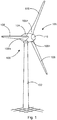
- Fig. 1 shows a schematic representation of a wind turbine according to the invention.
- the wind energy installation 100 has a tower 102 and a nacelle 104 on the tower 102.
- An aerodynamic rotor 106 with three rotor blades 108 and a hub 110 is provided on the nacelle 104.
- the aerodynamic rotor 106 is caused to rotate by the wind during operation of the wind energy installation and thus also rotates an electrodynamic rotor or rotor of a generator, which is coupled directly or indirectly to the aerodynamic rotor 106.
- the electrical generator is arranged in the nacelle 104 and generates electrical energy.
- the pitch angles of the rotor blades 108 can be changed by pitch motors at the rotor blade roots of the respective rotor blades 108.
- the rotor blades 108 are attached to the hub 110 via a blade bearing 200.
- a bearing cover 300 protects this area from environmental influences. Details of the fastening of the rotor blade 108 to the hub 110 and of the blade bearing 200 and the bearing cover 300 are given below, in particular with reference to FIG Figures 2 to 6 and 12th described in more detail. In the Figures 7 and 8th further details of a way of inspecting the bearing are shown. In the Figures 9 to 11 details of a locking device 400 for locking the rotor blade 108 with respect to the hub 110 are shown.
- Figure 14 finally, schematically shows the steps of a method 1000 for connecting a rotor blade 108 to a hub 110 of a rotor 106 of a wind energy installation 100.
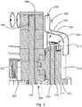
- a rotor blade 108 is fastened with its hub-side end 108n to the hub 110 of a rotor 106 of a wind energy installation 100.
- the rotor blade fastening described here can equally be used for hubs which have hub adapters for fastening the rotor blade.
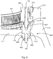
- the rotor blade 108 is fastened to the hub 110 via a blade bearing 200.
- the blade bearing 200 comprises a stationary part 210 and a movable part 220.
- the stationary part 210 of the blade bearing 200 is attached to the hub 110 by means of a plurality of bearing fastening bolts 240.
- These bearing fastening bolts 240 engage through corresponding through holes 211 in the stationary part 210 of the blade bearing 200 and ends in corresponding hub blind holes 242 of the hub 110.
- the heads 241 of the bearing fastening bolts 240 protrude into the space 350 of the bearing cover 300 and are like that protected from environmental influences.
- the hub-side end 108n of the rotor blade 108 is fastened to the movable part 220 of the blade bearing 200 by means of a plurality of blade fastening bolts 140.
- the blade fastening bolts 140 penetrate corresponding through holes 221 in the movable part 220 of the blade bearing 200 and end in corresponding blind blade holes 142 in the rotor blade 108.
- the heads 141 of the blade fastening bolts 140 are accessible via elongated holes 112 in the radially projecting flange 111 of the hub 110.
- the blade fastening bolts 140 are hydraulically pulled a little out of the through holes 221 in the movable part 220 of the blade bearing 200 and then the nuts of the heads 141 of the blade fastening bolts 140 are screwed on. Then the hydraulic tension is released, resulting in a tightly tensioned blade attachment. In this way, torque limitation when attaching the nuts to the heads 141 of the blade fastening bolts 140 can preferably also be dispensed with.
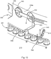
- Figure 12 shows the movable part 220 of the blade bearing as a split inner ring with an upper part 220a and a lower part 220b and the division 220c.
- the rolling elements 230 here in the form of rollers, are shown in FIG Figure 12 recognizable.
- the fixed part 210 of the blade bearing 200 is designed as a so-called nose ring and the movable part 220 of the blade bearing 200 is designed as a split U-ring.
- a reverse design is also possible, in which the fixed part 210 of the blade bearing 200 is designed as a split U-ring and the movable part 220 of the blade bearing 200 is designed as a nose ring.
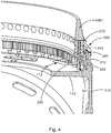
- a bearing cover 300 is arranged on an outer circumferential surface 108 of the hub-side end 108n of the rotor blade 108.
- the bearing cover 300 serves in particular to protect the area of the connection between rotor blade 108 and hub 110 that it covers, for example from environmental influences and, for example, to reduce the entry of rain and / or dirt. This is particularly advantageous in the case of wind energy installations 100, the rotor 106 of which does not have a spinner.
- a sealing element 370 is preferably provided which at least partially seals and / or covers a gap between the outer circumferential surface 108u of the hub-side end 108n of the rotor blade 108 and the portion 330 of the bearing cover 300 remote from the bearing. This can reduce the entry of dirt and moisture into the gap, for example.
- a liquid-tight seal i.e. not only reducing the entry of liquid, can also be provided.
- the bearing cover 300 comprises a portion 310 near the bearing and a portion 330 remote from the bearing.
- the portion 310 near the bearing is many times farther away from the outer circumferential surface 108u of the hub-side end 108n of the rotor blade 108 than the portion 330 remote from the bearing.
- a gap 350 is formed between the outer circumferential surface 108u of the hub-side end 108n of the rotor blade 108 and the portion 310 of the bearing cover 300 near the bearing.
- This serves in particular to receive a section of a stationary part 210 of the blade bearing 220, in particular to receive the heads 241 of the bearing fastening bolts 240.
- the bearing cover 300, in particular its interspace 350 is arranged and designed to accommodate the heads 241 of the Bearing mounting bolt 240.
- the section 330 remote from the bearing and the section 310 of the bearing cover close to the bearing are preferably arranged essentially parallel to one another and / or radially spaced from one another.
- the section 330 remote from the bearing and the section 310 of the bearing cover 300 near the bearing preferably extend essentially in the direction of the longitudinal axis of the rotor blade.
- the bearing cover 300 has an intermediate section 320 which is arranged between the section 330 remote from the bearing and the section 310 near the bearing.
- the intermediate section 320 has a main direction of extent that is slightly inclined to a radially oriented plane.
- the intermediate section 320 is also designed in the shape of an annular disk.
- the intermediate section 320 connects the section 330 remote from the bearing with that near the bearing Section 320 the transitions from the section 330 remote from the bearing to the intermediate section 320 and from the section 310 near the bearing to the intermediate section 320 are rounded.
- the transition from the section 330 remote from the bearing to the intermediate section 320 is rounded in a different direction than the transition from the section 310 near the bearing to the intermediate section 320.
- the portion 330 remote from the bearing, the portion 310 near the bearing and the intermediate portion 320 are formed in one piece and formed from a single piece.
- the bearing cover 300 has several partial ring segments.
- the overall ring-shaped bearing cover 300 is thus preferably formed by a plurality of partial ring segments.
- the individual partial ring segments are preferably releasably connected to one another. These connections can be plug-in connections, overlap connections or other connections.
- the one-piece design of the section 330 remote from the bearing, the section 310 close to the bearing and the intermediate section 320 thus relates in particular to the design of a respective partial ring segment.
- the bearing cover 300 is releasably fastened in particular via its section 330 remote from the bearing to the outer circumferential surface 108u of the hub-side end 108n of the rotor blade 108, in particular by means of fastening elements 380 which, for example, through radial through-opening in the hub-side end 108n of the rotor blade 108 and corresponding recesses in the bearing-remote section 330 of the bearing cover 300 can be carried out.
- compensating elements for example in the form of disks, can preferably be arranged at the ends 360 of the transverse bolts.
- the compensating elements can preferably have different dimensions, for example different panes ticking, in order to be able to compensate for different deviations from the circular line K, for example inwards or outwards.
- the bearing cover 300 in particular its portion 330 remote from the bearing, can be designed in an annular manner and any deviations in the outer circumferential surface 108u of the hub-side end 108n of the rotor blade 108 can occur via the compensating elements be compensated, whereby assembly and tolerance problems can be avoided or reduced.
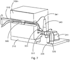
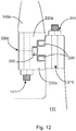
- radial through-openings 500 can be provided at the hub-side end 108n of the rotor blade 108.
- these through openings 500 can serve to receive the fastening elements 380 of the bearing cover 300.
- such through openings 500 can also be provided in order to enable access to the intermediate space 350 from the interior of the hub-side end 108n of the rotor blade 108. This access into the intermediate space 350 and in particular into the heads 241 of the bearing fastening bolts 240 protruding into this intermediate space is advantageous for inspection, maintenance or repair purposes.
- a through opening 500 is therefore preferably designed to receive at least one functional element through it, in particular, for example, a handling device 510 with a gripper 511 and / or an inspection device 520, which for example also has a temperature sensor 530 with a corresponding line 531 and / or a measuring head 540 a corresponding line 541 may comprise. Further or different sensors can also be provided.
- the intermediate space 350 can be made accessible by means of the radial through openings 500 in order to be able to check elements located there.
- the bearing cover 300 can preferably be completely or partially dismantled beforehand. In particular, a partial ring segment can be dismantled for this purpose, as in FIG Figure 5 shown.
- a camera 500 in the space 350 or with the bearing cover 300 completely or partially dismantled, with which, for example, the handling device 510 and / or the gripper 511 and / or the inspection device 520 can be captured. This can, for example, facilitate the control and / or monitoring of the handling device 510 and / or the gripper 511 and / or the inspection device 520.
- Another advantage of the design of the bearing cover 300 in several partial ring segments is that the partial ring segments are also easier and cheaper to transport and assemble than a closed ring.
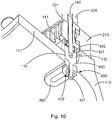
- a, preferably detachable or temporarily attachable, locking device 400 is provided with which the rotor blade 108 can be locked with respect to the hub 110. This may be necessary, for example in order to prevent a rotational movement of the rotor blade 108 with respect to the hub 110, for example to replace or repair a pitch motor.
- the locking device 400 has a locking pin 410, at the fastening end 420 of which a recess 421 is provided. With this, the locking pin 410 can come into engagement with the head 141 of a blade fastening bolt 140, for example via a threaded connection.
- an elongated hole insert 490 is provided through which the rod projection 431 of the locking pin 410 can protrude and can then be fastened with the fastening element 432.
- This engagement can also be designed, for example, as a releasable threaded connection.
- the locking device 400 thus makes it possible to lock the rotor blade 108 with respect to the hub 110. In this way, in particular, rotational movements of the rotor blade 108 with respect to the hub 110 can be prevented. If necessary, an axial movement of the rotor blade 108 with respect to the hub 110 can also be prevented.
- the illustrated method 1000 for connecting a rotor blade 108 of the hub 110 of a rotor 106 of a wind turbine 100 begins with the provision 1001 of a corresponding rotor blade 108 and then the fastening 1002 of the hub-side end 108n of the rotor blade 108 to a blade bearing 200 arranged on the hub 110 a pretensioning 1003, in particular hydraulic pretensioning, of the blade fastening bolts 140, through the elongated hole 112 on the flange 111 of the hub 110, followed by screwing 1004 nuts onto the heads 141 of the blade fastening bolts 140 and a subsequent partial relaxation 1005 of the blade fastening bolts 140.
- the solution described here provides a simple and inexpensive solution for connecting a rotor blade to the hub, which ensures a secure and reliable connection due to the bearing cover provided and is at the same time easy to assemble and service.
Landscapes
- Engineering & Computer Science (AREA)
- Life Sciences & Earth Sciences (AREA)
- Sustainable Development (AREA)
- Sustainable Energy (AREA)
- Chemical & Material Sciences (AREA)
- Combustion & Propulsion (AREA)
- Mechanical Engineering (AREA)
- General Engineering & Computer Science (AREA)
- Wind Motors (AREA)
Applications Claiming Priority (1)
| Application Number | Priority Date | Filing Date | Title |
|---|---|---|---|
| DE102019131493 | 2019-11-21 |
Publications (2)
| Publication Number | Publication Date |
|---|---|
| EP3825545A1 true EP3825545A1 (fr) | 2021-05-26 |
| EP3825545B1 EP3825545B1 (fr) | 2022-06-01 |
Family
ID=73059450
Family Applications (1)
| Application Number | Title | Priority Date | Filing Date |
|---|---|---|---|
| EP20205258.5A Active EP3825545B1 (fr) | 2019-11-21 | 2020-11-02 | Pale de rotor, rotor et éolienne, ainsi que procédé |
Country Status (4)
| Country | Link |
|---|---|
| US (1) | US11624352B2 (fr) |
| EP (1) | EP3825545B1 (fr) |
| CN (1) | CN112824672A (fr) |
| DK (1) | DK3825545T3 (fr) |
Families Citing this family (1)
| Publication number | Priority date | Publication date | Assignee | Title |
|---|---|---|---|---|
| CN114067221B (zh) * | 2022-01-14 | 2022-04-15 | 成都数联云算科技有限公司 | 一种遥感影像林地提取方法及系统及装置及介质 |
Citations (6)
| Publication number | Priority date | Publication date | Assignee | Title |
|---|---|---|---|---|
| DE102007052383A1 (de) | 2006-10-31 | 2008-05-08 | Imo Holding Gmbh | Wälzlageranordnung |
| DE102007032937A1 (de) | 2007-07-14 | 2009-01-22 | Nordex Energy Gmbh | Schutzvorrichtung zum Schutz eines Blattlagers einer Windenergieanlage |
| EP2527676A1 (fr) | 2011-08-03 | 2012-11-28 | IMO Holding GmbH | Procédé de production d'un serrage mécanique et dispositif de serrage mécanique d'au moins un boulonnage |
| WO2012175204A1 (fr) | 2011-06-21 | 2012-12-27 | Imo Holding Gmbh | Palier d'aube pour une éolienne, ainsi que son procédé de fabrication |
| DE102016203269A1 (de) | 2016-02-29 | 2017-08-31 | Innogy Se | Windkraftanlage mit verbesserter Rotorblattverschraubung |
| US20190331091A1 (en) * | 2016-12-28 | 2019-10-31 | Vestas Wind Systems A/S | Joint for connecting a wind turbine rotor blade to a rotor hub and associated methods |
Family Cites Families (9)
| Publication number | Priority date | Publication date | Assignee | Title |
|---|---|---|---|---|
| CN101238287B (zh) * | 2005-07-08 | 2011-05-11 | 维斯塔斯风力系统有限公司 | 风轮机、风轮机用的轮毂及其使用 |
| EP1925860A1 (fr) * | 2006-11-02 | 2008-05-28 | Ecotecnia Energias Renovables S.L. | Dispositif de mise en place d'un joint |
| US8043012B2 (en) * | 2009-09-30 | 2011-10-25 | General Electric Company | Seal arrangement and a brush seal for a wind turbine |
| CN101915211B (zh) * | 2010-08-19 | 2012-05-30 | 三一电气有限责任公司 | 风力发电机组及其变桨系统 |
| TWI441981B (zh) * | 2011-11-25 | 2014-06-21 | Ind Tech Res Inst | 風力機輪轂密封裝置 |
| US8591187B2 (en) * | 2011-12-06 | 2013-11-26 | General Electric Company | System and method for detecting loads transmitted through a blade root of a wind turbine rotor blade |
| EP3190290A1 (fr) * | 2013-11-27 | 2017-07-12 | Nordex Energy GmbH | Pale de rotor d'éolienne pour un rotor avec cône |
| DE202016106250U1 (de) * | 2016-11-09 | 2016-11-22 | WP Systems GmbH | Dichtungsanordnung |
| DE102017104474A1 (de) * | 2017-03-03 | 2018-09-06 | Wobben Properties Gmbh | Verstelleinheit für eine Azimutverstellung und/oder für eine Pitchverstellung einer Windenergieanlage und Verfahren |
-
2020
- 2020-11-02 EP EP20205258.5A patent/EP3825545B1/fr active Active
- 2020-11-02 DK DK20205258.5T patent/DK3825545T3/da active
- 2020-11-19 CN CN202011301196.XA patent/CN112824672A/zh active Pending
- 2020-11-20 US US17/100,392 patent/US11624352B2/en active Active
Patent Citations (6)
| Publication number | Priority date | Publication date | Assignee | Title |
|---|---|---|---|---|
| DE102007052383A1 (de) | 2006-10-31 | 2008-05-08 | Imo Holding Gmbh | Wälzlageranordnung |
| DE102007032937A1 (de) | 2007-07-14 | 2009-01-22 | Nordex Energy Gmbh | Schutzvorrichtung zum Schutz eines Blattlagers einer Windenergieanlage |
| WO2012175204A1 (fr) | 2011-06-21 | 2012-12-27 | Imo Holding Gmbh | Palier d'aube pour une éolienne, ainsi que son procédé de fabrication |
| EP2527676A1 (fr) | 2011-08-03 | 2012-11-28 | IMO Holding GmbH | Procédé de production d'un serrage mécanique et dispositif de serrage mécanique d'au moins un boulonnage |
| DE102016203269A1 (de) | 2016-02-29 | 2017-08-31 | Innogy Se | Windkraftanlage mit verbesserter Rotorblattverschraubung |
| US20190331091A1 (en) * | 2016-12-28 | 2019-10-31 | Vestas Wind Systems A/S | Joint for connecting a wind turbine rotor blade to a rotor hub and associated methods |
Also Published As
| Publication number | Publication date |
|---|---|
| US20210156364A1 (en) | 2021-05-27 |
| CN112824672A (zh) | 2021-05-21 |
| DK3825545T3 (da) | 2022-07-04 |
| US11624352B2 (en) | 2023-04-11 |
| EP3825545B1 (fr) | 2022-06-01 |
Similar Documents
| Publication | Publication Date | Title |
|---|---|---|
| EP2619447B1 (fr) | Raccord de pale d'une pale de rotor d'une installation éolienne | |
| EP1251268B1 (fr) | Dispositif de connexion des arbres d'une éolienne | |
| EP2368037B1 (fr) | Dispositif de blocage pour un rotor d'éolienne | |
| EP4038271B1 (fr) | Pale de rotor d'éolienne et procédé de liaison de deux segments de pale de rotor | |
| DE4221783C2 (de) | Vorrichtung zur Verstellung von Rotorblättern | |
| EP2218908B1 (fr) | Eolienne avec un dispositif d'arrêt d'une pale | |
| EP3047144B1 (fr) | Dispositif, système et procédé permettant de surveiller un raccord à brides d'une éolienne | |
| EP3469212B1 (fr) | Rotor pour éolienne, pale de rotor pour éolienne, manchon et procédé de montage d'un rotor | |
| EP2420670B1 (fr) | Dispositif de verrouillage de rotor et procédé d'arrêt d'un rotor d'une éolienne | |
| DE102010010639A1 (de) | Drehverbindung eines Rotorblattes mit der Rotornabe einer Windkraftanlage | |
| EP2154367B1 (fr) | Procédé de montage d'un moyeu d'hélice sur un arbre de rotor d'une éolienne et éolienne | |
| EP3396154B1 (fr) | Adaptateur de pale pour éoliennes | |
| EP3377758B1 (fr) | Pale de rotor d'éolienne et éolienne | |
| EP3350464A1 (fr) | Train planétaire destiné à une éolienne, muni de pignons satellites montés sur palier lisse | |
| DE102011002488A1 (de) | Anordnung von Bauteilen einer Windenergieanlage | |
| DE19644705A1 (de) | Vorrichtung zur Verstellung von Rotorblättern | |
| DE102018002553A1 (de) | Maschinenträger für Windenergieanlagen | |
| EP3333439B1 (fr) | Procédé de remplacement du palier usé, en particulier de remplacement du palier de grand diamètre comme palier principal d'une éolienne et dispositif de palier | |
| EP3495626A1 (fr) | Raccordement de levier et turbomachine associée | |
| EP3929431A1 (fr) | Module et procédé de raccordement de deux segments de pale de rotor d'une pale de rotor d'éolienne | |
| EP3825545B1 (fr) | Pale de rotor, rotor et éolienne, ainsi que procédé | |
| EP4291790B1 (fr) | Dispositif d'entraînement et/ou de réglage à protection contre les surcharges | |
| EP3891383B1 (fr) | Rotor pour éolienne et procédé | |
| EP2816198B1 (fr) | Ensemble d'aube directrice, aube directrice et procédé de montage d'une aube directrice | |
| WO2024223500A1 (fr) | Dispositif de fixation d'une pale de rotor sur un corps de moyeu et ensemble moyeu en plusieurs parties pour une éolienne |
Legal Events
| Date | Code | Title | Description |
|---|---|---|---|
| PUAI | Public reference made under article 153(3) epc to a published international application that has entered the european phase |
Free format text: ORIGINAL CODE: 0009012 |
|
| STAA | Information on the status of an ep patent application or granted ep patent |
Free format text: STATUS: THE APPLICATION HAS BEEN PUBLISHED |
|
| AK | Designated contracting states |
Kind code of ref document: A1 Designated state(s): AL AT BE BG CH CY CZ DE DK EE ES FI FR GB GR HR HU IE IS IT LI LT LU LV MC MK MT NL NO PL PT RO RS SE SI SK SM TR |
|
| STAA | Information on the status of an ep patent application or granted ep patent |
Free format text: STATUS: REQUEST FOR EXAMINATION WAS MADE |
|
| 17P | Request for examination filed |
Effective date: 20210927 |
|
| RBV | Designated contracting states (corrected) |
Designated state(s): AL AT BE BG CH CY CZ DE DK EE ES FI FR GB GR HR HU IE IS IT LI LT LU LV MC MK MT NL NO PL PT RO RS SE SI SK SM TR |
|
| RIC1 | Information provided on ipc code assigned before grant |
Ipc: F03D 80/70 20160101ALI20211102BHEP Ipc: F03D 1/06 20060101AFI20211102BHEP |
|
| GRAP | Despatch of communication of intention to grant a patent |
Free format text: ORIGINAL CODE: EPIDOSNIGR1 |
|
| STAA | Information on the status of an ep patent application or granted ep patent |
Free format text: STATUS: GRANT OF PATENT IS INTENDED |
|
| INTG | Intention to grant announced |
Effective date: 20220111 |
|
| GRAS | Grant fee paid |
Free format text: ORIGINAL CODE: EPIDOSNIGR3 |
|
| GRAA | (expected) grant |
Free format text: ORIGINAL CODE: 0009210 |
|
| STAA | Information on the status of an ep patent application or granted ep patent |
Free format text: STATUS: THE PATENT HAS BEEN GRANTED |
|
| AK | Designated contracting states |
Kind code of ref document: B1 Designated state(s): AL AT BE BG CH CY CZ DE DK EE ES FI FR GB GR HR HU IE IS IT LI LT LU LV MC MK MT NL NO PL PT RO RS SE SI SK SM TR |
|
| REG | Reference to a national code |
Ref country code: GB Ref legal event code: FG4D Free format text: NOT ENGLISH |
|
| REG | Reference to a national code |
Ref country code: AT Ref legal event code: REF Ref document number: 1495515 Country of ref document: AT Kind code of ref document: T Effective date: 20220615 Ref country code: CH Ref legal event code: EP Ref country code: DE Ref legal event code: R096 Ref document number: 502020001171 Country of ref document: DE |
|
| REG | Reference to a national code |
Ref country code: IE Ref legal event code: FG4D Free format text: LANGUAGE OF EP DOCUMENT: GERMAN |
|
| REG | Reference to a national code |
Ref country code: DK Ref legal event code: T3 Effective date: 20220629 |
|
| REG | Reference to a national code |
Ref country code: NL Ref legal event code: FP |
|
| REG | Reference to a national code |
Ref country code: LT Ref legal event code: MG9D |
|
| PG25 | Lapsed in a contracting state [announced via postgrant information from national office to epo] |
Ref country code: SE Free format text: LAPSE BECAUSE OF FAILURE TO SUBMIT A TRANSLATION OF THE DESCRIPTION OR TO PAY THE FEE WITHIN THE PRESCRIBED TIME-LIMIT Effective date: 20220601 Ref country code: NO Free format text: LAPSE BECAUSE OF FAILURE TO SUBMIT A TRANSLATION OF THE DESCRIPTION OR TO PAY THE FEE WITHIN THE PRESCRIBED TIME-LIMIT Effective date: 20220901 Ref country code: LT Free format text: LAPSE BECAUSE OF FAILURE TO SUBMIT A TRANSLATION OF THE DESCRIPTION OR TO PAY THE FEE WITHIN THE PRESCRIBED TIME-LIMIT Effective date: 20220601 Ref country code: HR Free format text: LAPSE BECAUSE OF FAILURE TO SUBMIT A TRANSLATION OF THE DESCRIPTION OR TO PAY THE FEE WITHIN THE PRESCRIBED TIME-LIMIT Effective date: 20220601 Ref country code: GR Free format text: LAPSE BECAUSE OF FAILURE TO SUBMIT A TRANSLATION OF THE DESCRIPTION OR TO PAY THE FEE WITHIN THE PRESCRIBED TIME-LIMIT Effective date: 20220902 Ref country code: FI Free format text: LAPSE BECAUSE OF FAILURE TO SUBMIT A TRANSLATION OF THE DESCRIPTION OR TO PAY THE FEE WITHIN THE PRESCRIBED TIME-LIMIT Effective date: 20220601 Ref country code: BG Free format text: LAPSE BECAUSE OF FAILURE TO SUBMIT A TRANSLATION OF THE DESCRIPTION OR TO PAY THE FEE WITHIN THE PRESCRIBED TIME-LIMIT Effective date: 20220901 |
|
| PG25 | Lapsed in a contracting state [announced via postgrant information from national office to epo] |
Ref country code: RS Free format text: LAPSE BECAUSE OF FAILURE TO SUBMIT A TRANSLATION OF THE DESCRIPTION OR TO PAY THE FEE WITHIN THE PRESCRIBED TIME-LIMIT Effective date: 20220601 Ref country code: PL Free format text: LAPSE BECAUSE OF FAILURE TO SUBMIT A TRANSLATION OF THE DESCRIPTION OR TO PAY THE FEE WITHIN THE PRESCRIBED TIME-LIMIT Effective date: 20220601 Ref country code: LV Free format text: LAPSE BECAUSE OF FAILURE TO SUBMIT A TRANSLATION OF THE DESCRIPTION OR TO PAY THE FEE WITHIN THE PRESCRIBED TIME-LIMIT Effective date: 20220601 |
|
| PG25 | Lapsed in a contracting state [announced via postgrant information from national office to epo] |
Ref country code: SM Free format text: LAPSE BECAUSE OF FAILURE TO SUBMIT A TRANSLATION OF THE DESCRIPTION OR TO PAY THE FEE WITHIN THE PRESCRIBED TIME-LIMIT Effective date: 20220601 Ref country code: SK Free format text: LAPSE BECAUSE OF FAILURE TO SUBMIT A TRANSLATION OF THE DESCRIPTION OR TO PAY THE FEE WITHIN THE PRESCRIBED TIME-LIMIT Effective date: 20220601 Ref country code: RO Free format text: LAPSE BECAUSE OF FAILURE TO SUBMIT A TRANSLATION OF THE DESCRIPTION OR TO PAY THE FEE WITHIN THE PRESCRIBED TIME-LIMIT Effective date: 20220601 Ref country code: PT Free format text: LAPSE BECAUSE OF FAILURE TO SUBMIT A TRANSLATION OF THE DESCRIPTION OR TO PAY THE FEE WITHIN THE PRESCRIBED TIME-LIMIT Effective date: 20221003 Ref country code: ES Free format text: LAPSE BECAUSE OF FAILURE TO SUBMIT A TRANSLATION OF THE DESCRIPTION OR TO PAY THE FEE WITHIN THE PRESCRIBED TIME-LIMIT Effective date: 20220601 Ref country code: EE Free format text: LAPSE BECAUSE OF FAILURE TO SUBMIT A TRANSLATION OF THE DESCRIPTION OR TO PAY THE FEE WITHIN THE PRESCRIBED TIME-LIMIT Effective date: 20220601 Ref country code: CZ Free format text: LAPSE BECAUSE OF FAILURE TO SUBMIT A TRANSLATION OF THE DESCRIPTION OR TO PAY THE FEE WITHIN THE PRESCRIBED TIME-LIMIT Effective date: 20220601 |
|
| PG25 | Lapsed in a contracting state [announced via postgrant information from national office to epo] |
Ref country code: IS Free format text: LAPSE BECAUSE OF FAILURE TO SUBMIT A TRANSLATION OF THE DESCRIPTION OR TO PAY THE FEE WITHIN THE PRESCRIBED TIME-LIMIT Effective date: 20221001 |
|
| REG | Reference to a national code |
Ref country code: DE Ref legal event code: R097 Ref document number: 502020001171 Country of ref document: DE |
|
| PG25 | Lapsed in a contracting state [announced via postgrant information from national office to epo] |
Ref country code: AL Free format text: LAPSE BECAUSE OF FAILURE TO SUBMIT A TRANSLATION OF THE DESCRIPTION OR TO PAY THE FEE WITHIN THE PRESCRIBED TIME-LIMIT Effective date: 20220601 |
|
| PLBE | No opposition filed within time limit |
Free format text: ORIGINAL CODE: 0009261 |
|
| STAA | Information on the status of an ep patent application or granted ep patent |
Free format text: STATUS: NO OPPOSITION FILED WITHIN TIME LIMIT |
|
| 26N | No opposition filed |
Effective date: 20230302 |
|
| PG25 | Lapsed in a contracting state [announced via postgrant information from national office to epo] |
Ref country code: SI Free format text: LAPSE BECAUSE OF FAILURE TO SUBMIT A TRANSLATION OF THE DESCRIPTION OR TO PAY THE FEE WITHIN THE PRESCRIBED TIME-LIMIT Effective date: 20220601 |
|
| PG25 | Lapsed in a contracting state [announced via postgrant information from national office to epo] |
Ref country code: MC Free format text: LAPSE BECAUSE OF FAILURE TO SUBMIT A TRANSLATION OF THE DESCRIPTION OR TO PAY THE FEE WITHIN THE PRESCRIBED TIME-LIMIT Effective date: 20220601 |
|
| REG | Reference to a national code |
Ref country code: BE Ref legal event code: MM Effective date: 20221130 |
|
| PG25 | Lapsed in a contracting state [announced via postgrant information from national office to epo] |
Ref country code: LU Free format text: LAPSE BECAUSE OF NON-PAYMENT OF DUE FEES Effective date: 20221102 |
|
| PG25 | Lapsed in a contracting state [announced via postgrant information from national office to epo] |
Ref country code: IE Free format text: LAPSE BECAUSE OF NON-PAYMENT OF DUE FEES Effective date: 20221102 |
|
| PG25 | Lapsed in a contracting state [announced via postgrant information from national office to epo] |
Ref country code: BE Free format text: LAPSE BECAUSE OF NON-PAYMENT OF DUE FEES Effective date: 20221130 |
|
| PG25 | Lapsed in a contracting state [announced via postgrant information from national office to epo] |
Ref country code: IT Free format text: LAPSE BECAUSE OF FAILURE TO SUBMIT A TRANSLATION OF THE DESCRIPTION OR TO PAY THE FEE WITHIN THE PRESCRIBED TIME-LIMIT Effective date: 20220601 |
|
| PG25 | Lapsed in a contracting state [announced via postgrant information from national office to epo] |
Ref country code: CY Free format text: LAPSE BECAUSE OF FAILURE TO SUBMIT A TRANSLATION OF THE DESCRIPTION OR TO PAY THE FEE WITHIN THE PRESCRIBED TIME-LIMIT Effective date: 20220601 |
|
| PG25 | Lapsed in a contracting state [announced via postgrant information from national office to epo] |
Ref country code: MK Free format text: LAPSE BECAUSE OF FAILURE TO SUBMIT A TRANSLATION OF THE DESCRIPTION OR TO PAY THE FEE WITHIN THE PRESCRIBED TIME-LIMIT Effective date: 20220601 |
|
| REG | Reference to a national code |
Ref country code: CH Ref legal event code: PL |
|
| PG25 | Lapsed in a contracting state [announced via postgrant information from national office to epo] |
Ref country code: CH Free format text: LAPSE BECAUSE OF NON-PAYMENT OF DUE FEES Effective date: 20231130 |
|
| PG25 | Lapsed in a contracting state [announced via postgrant information from national office to epo] |
Ref country code: HU Free format text: LAPSE BECAUSE OF FAILURE TO SUBMIT A TRANSLATION OF THE DESCRIPTION OR TO PAY THE FEE WITHIN THE PRESCRIBED TIME-LIMIT; INVALID AB INITIO Effective date: 20201102 Ref country code: CH Free format text: LAPSE BECAUSE OF NON-PAYMENT OF DUE FEES Effective date: 20231130 |
|
| PG25 | Lapsed in a contracting state [announced via postgrant information from national office to epo] |
Ref country code: MT Free format text: LAPSE BECAUSE OF FAILURE TO SUBMIT A TRANSLATION OF THE DESCRIPTION OR TO PAY THE FEE WITHIN THE PRESCRIBED TIME-LIMIT Effective date: 20220601 |
|
| PG25 | Lapsed in a contracting state [announced via postgrant information from national office to epo] |
Ref country code: BG Free format text: LAPSE BECAUSE OF FAILURE TO SUBMIT A TRANSLATION OF THE DESCRIPTION OR TO PAY THE FEE WITHIN THE PRESCRIBED TIME-LIMIT Effective date: 20220601 |
|
| PG25 | Lapsed in a contracting state [announced via postgrant information from national office to epo] |
Ref country code: BG Free format text: LAPSE BECAUSE OF FAILURE TO SUBMIT A TRANSLATION OF THE DESCRIPTION OR TO PAY THE FEE WITHIN THE PRESCRIBED TIME-LIMIT Effective date: 20220601 |
|
| PGFP | Annual fee paid to national office [announced via postgrant information from national office to epo] |
Ref country code: TR Payment date: 20241024 Year of fee payment: 5 |
|
| PGFP | Annual fee paid to national office [announced via postgrant information from national office to epo] |
Ref country code: NL Payment date: 20251119 Year of fee payment: 6 |
|
| PGFP | Annual fee paid to national office [announced via postgrant information from national office to epo] |
Ref country code: DE Payment date: 20251201 Year of fee payment: 6 |
|
| PGFP | Annual fee paid to national office [announced via postgrant information from national office to epo] |
Ref country code: GB Payment date: 20251120 Year of fee payment: 6 |
|
| PGFP | Annual fee paid to national office [announced via postgrant information from national office to epo] |
Ref country code: AT Payment date: 20260113 Year of fee payment: 5 |
|
| PGFP | Annual fee paid to national office [announced via postgrant information from national office to epo] |
Ref country code: DK Payment date: 20251119 Year of fee payment: 6 |
|
| PGFP | Annual fee paid to national office [announced via postgrant information from national office to epo] |
Ref country code: FR Payment date: 20251125 Year of fee payment: 6 |