EP3929431A1 - Module et procédé de raccordement de deux segments de pale de rotor d'une pale de rotor d'éolienne - Google Patents
Module et procédé de raccordement de deux segments de pale de rotor d'une pale de rotor d'éolienne Download PDFInfo
- Publication number
- EP3929431A1 EP3929431A1 EP20181436.5A EP20181436A EP3929431A1 EP 3929431 A1 EP3929431 A1 EP 3929431A1 EP 20181436 A EP20181436 A EP 20181436A EP 3929431 A1 EP3929431 A1 EP 3929431A1
- Authority
- EP
- European Patent Office
- Prior art keywords
- assembly
- piece
- rotor blade
- kit
- pressure piece
- Prior art date
- Legal status (The legal status is an assumption and is not a legal conclusion. Google has not performed a legal analysis and makes no representation as to the accuracy of the status listed.)
- Granted
Links
Images



Classifications
-
- F—MECHANICAL ENGINEERING; LIGHTING; HEATING; WEAPONS; BLASTING
- F03—MACHINES OR ENGINES FOR LIQUIDS; WIND, SPRING, OR WEIGHT MOTORS; PRODUCING MECHANICAL POWER OR A REACTIVE PROPULSIVE THRUST, NOT OTHERWISE PROVIDED FOR
- F03D—WIND MOTORS
- F03D1/00—Wind motors with rotation axis substantially parallel to the air flow entering the rotor
- F03D1/06—Rotors
- F03D1/065—Rotors characterised by their construction elements
- F03D1/0675—Rotors characterised by their construction elements of the blades
-
- F—MECHANICAL ENGINEERING; LIGHTING; HEATING; WEAPONS; BLASTING
- F03—MACHINES OR ENGINES FOR LIQUIDS; WIND, SPRING, OR WEIGHT MOTORS; PRODUCING MECHANICAL POWER OR A REACTIVE PROPULSIVE THRUST, NOT OTHERWISE PROVIDED FOR
- F03D—WIND MOTORS
- F03D13/00—Assembly, mounting or commissioning of wind motors; Arrangements specially adapted for transporting wind motor components
- F03D13/10—Assembly of wind motors; Arrangements for erecting wind motors
-
- F—MECHANICAL ENGINEERING; LIGHTING; HEATING; WEAPONS; BLASTING
- F05—INDEXING SCHEMES RELATING TO ENGINES OR PUMPS IN VARIOUS SUBCLASSES OF CLASSES F01-F04
- F05B—INDEXING SCHEME RELATING TO WIND, SPRING, WEIGHT, INERTIA OR LIKE MOTORS, TO MACHINES OR ENGINES FOR LIQUIDS COVERED BY SUBCLASSES F03B, F03D AND F03G
- F05B2240/00—Components
- F05B2240/20—Rotors
- F05B2240/30—Characteristics of rotor blades, i.e. of any element transforming dynamic fluid energy to or from rotational energy and being attached to a rotor
- F05B2240/302—Segmented or sectional blades
-
- F—MECHANICAL ENGINEERING; LIGHTING; HEATING; WEAPONS; BLASTING
- F05—INDEXING SCHEMES RELATING TO ENGINES OR PUMPS IN VARIOUS SUBCLASSES OF CLASSES F01-F04
- F05B—INDEXING SCHEME RELATING TO WIND, SPRING, WEIGHT, INERTIA OR LIKE MOTORS, TO MACHINES OR ENGINES FOR LIQUIDS COVERED BY SUBCLASSES F03B, F03D AND F03G
- F05B2260/00—Function
- F05B2260/30—Retaining components in desired mutual position
- F05B2260/301—Retaining bolts or nuts
-
- Y—GENERAL TAGGING OF NEW TECHNOLOGICAL DEVELOPMENTS; GENERAL TAGGING OF CROSS-SECTIONAL TECHNOLOGIES SPANNING OVER SEVERAL SECTIONS OF THE IPC; TECHNICAL SUBJECTS COVERED BY FORMER USPC CROSS-REFERENCE ART COLLECTIONS [XRACs] AND DIGESTS
- Y02—TECHNOLOGIES OR APPLICATIONS FOR MITIGATION OR ADAPTATION AGAINST CLIMATE CHANGE
- Y02E—REDUCTION OF GREENHOUSE GAS [GHG] EMISSIONS, RELATED TO ENERGY GENERATION, TRANSMISSION OR DISTRIBUTION
- Y02E10/00—Energy generation through renewable energy sources
- Y02E10/70—Wind energy
- Y02E10/72—Wind turbines with rotation axis in wind direction
Definitions
- the invention relates to a kit and a method for connecting two rotor blade segments of a wind turbine rotor blade.
- Wind energy installations with wind energy installation rotor blades are widely known from the prior art and are used to convert wind energy into electrical energy.
- Wind energy plants have a large number of components that are connected to one another, for example by means of a flange connection.
- the rotor blades have a rotor blade connection with a large number of connecting means integrated into the laminate, via which the rotor blades are connected to a bearing ring of a so-called pitch bearing or to a component connected to the bearing ring such as a so-called extender by means of fastening screws or fastening bolts connected to the wind turbine.
- the connecting means can, for example, be designed as cross bolts or as bearing sleeves and be part of a flange insert for the rotor blade connection.
- Such a structure is, for example, from the international application WO 2015/124568 A1 known.
- (flange) connections are also used to connect rotor blade segments which, arranged lengthways and joined together, form a rotor blade.
- a rotor blade is called a split or segmented one Called rotor blade.
- connecting elements are then located in the laminate of a connecting end or dividing flange of the rotor blade segments.
- the rotor blade segments can be connected to one another directly by means of screw bolts or via suitable spacers.
- Split rotor blades are to be preferred especially for reasons of transport and are becoming increasingly important, especially due to the increasing overall length of rotor blades.
- One object on which the invention is based is to provide an assembly concept for split rotor blades which ensures a particularly advantageous connection of rotor blade segments.
- a kit for connecting two rotor blade segments of a wind turbine rotor blade has a connecting bolt for screwing the two rotor blade segments together.
- the kit also has a pressure piece designed as a sleeve, which has a recess and which is arranged between the rotor blade segments in a connected state of the two rotor blade segments.
- the kit also has an assembly piece for an assembly tool for applying a screwing force.
- the kit is designed such that when the kit is properly installed to connect the two rotor blade segments, the connecting bolt is passed through the pressure piece in such a way that a mounting section of the connecting bolt is arranged in the region of the recess of the pressure piece.
- the assembly piece in the intended assembly state, can be detachably inserted into the recess of the pressure piece, so that the assembly piece is in the assembly section is both positively connected to the connecting bolt and positively connected to the pressure piece.
- the assembly piece can be removed from the pressure piece again.
- connection elements for example bearing sleeves
- connection ends to be connected.
- a large number of bolt connections are established between the two segments by means of the connecting elements.
- the assembly is planned in such a way that the connecting bolts are first screwed into a connection end of the one rotor blade segment. Then sleeve-shaped pressure pieces are pushed onto the connecting bolts before the free ends of the connecting bolts are threaded into the corresponding corresponding connecting elements of the other rotor blade segment and screwed.
- the two rotor blade segments are screwed together, the connection being firmly screwed and pretensioned by means of an assembly tool, for example a (hydraulic) tensioning tool.
- the pressure pieces are thus braced between the rotor blade segments.
- the kit described is intended to produce such a detachable connection between the two rotor blade segments of a wind turbine rotor blade.
- the kit disclosed provides that the assembly tool attaches to the detachable assembly piece and / or the pressure piece for screwing and bracing the two rotor blade segments.
- the components of the kit, i.e. the mounting piece, the mounting section of the bolt and the pressure piece are in particular designed accordingly with regard to their shape that they can be positively coupled to one another for assembly.
- the assembly piece In the assembled state, the assembly piece is releasably positively inserted into the corresponding recess of the pressure piece, with a positive, mechanical coupling to the connecting bolt also being established.
- the actuation of a tool attached to the mounting piece or the pressure piece causes a rotation to be transmitted to the connecting bolt via the mounting piece.
- the two rotor blade segments can be firmly screwed / braced together.
- the kit according to the solution according to the invention enables the installation space to be used effectively.
- the kit contributes to the fact that the pressure piece takes up considerably less space compared to a pressure piece, which has to provide a correspondingly large recess for the direct attachment of an assembly tool to the connecting bolt.
- the necessary installation space for the pressure piece is reduced.
- This makes it possible to use pressure pieces with a comparatively small outer diameter.
- a comparatively high number of corresponding pressure pieces and thus connecting bolts is possible overall over a circumference of a connecting area of the two rotor blade segments.
- the proposed kit prevents the force introduced from being transmitted directly from the pressure piece to the connecting bolt.
- the pressure piece would have to interact positively with the connecting bolts on the inside in order to rotate them accordingly during assembly.
- the connecting bolt In the intended installation state, i.e. when the two rotor blade segments are connected, there would always be a mechanical interaction between the connecting bolt and the associated pressure piece, which would cause stresses and strains in both components, which would result in a reduced service life of the blade segment connections.
- Such a solution would also require pressure pieces that are complex in terms of production technology.
- the detachable assembly piece can be used again at a different connection point of the two rotor blade segments.
- a large number of connecting bolts are used to connect the two rotor blade segments, for example more than 40 pieces, so that a mounting piece does not necessarily have to be kept for each connection.
- At least all of the assembly pieces that are necessary for a segment connection can be used for the connection of further segments of further rotor blades. This contributes to lower costs in both assembly and manufacture.
- the kit enables a particularly simple and inexpensive production of the pressure piece, in particular from a simple semi-finished pipe product. This enables particularly low manufacturing costs.
- the kit also helps to enable a particularly rigid connection between the two blade segments.
- the absorption and transmission of particularly high tensile and compressive forces between the two rotor blade segments is made possible.
- a particularly efficient power transmission is made possible exclusively via the connecting bolt from one segment to the second segment, in particular after the assembly piece has been removed.
- Such a frictional connection is also referred to as "inline”.
- the blade segments are joined in a detachable manner without force deflections, as is the case with eccentric screw connections or intermediate pieces subject to tensile or bending loads.
- Such a frictional connection enables very good material utilization. It contributes to a low tendency for the connection to gape and to a bending load on the screw connections, especially in contrast to conventional flange connections.
- a uniform spacing of the connecting elements, such as the bearing sleeves, and thus connecting ends from one another is ensured over the entire circumference of the connection.
- the pressure piece is designed as a sleeve, that is to say the pressure piece has a continuous bore / opening along a main direction of extent, longitudinal axis.
- the pressure piece has at least one recess in a wall so that the continuous bore is accessible.
- the pressure piece is designed, for example, as a clamping sleeve.
- the assembly piece is an auxiliary element by means of which a rotary movement of an assembly tool, which attaches to the assembly piece and / or the pressure piece, can be transmitted to the connecting bolt.
- the assembly piece is in positive engagement with a Assembly tool during the intended assembly state for connecting the two rotor blade segments.
- the assembly piece has, for example, one or more tool surfaces that are in direct, form-fitting contact with the corresponding assembly workpiece during assembly.
- the assembly piece has a corresponding shape which is adapted to a shape of the recess of the pressure piece.
- the assembly piece is at least partially adapted in terms of its shape to the assembly section of the connecting bolt in such a way that, in turn, a form-fitting connection is provided.
- the form-fitting connections are such that a torque about the longitudinal axis of the pressure piece can be transmitted to the inserted or pushed-in connecting bolt.
- the attachment of the assembly tool to the detachable assembly piece and / or the pressure piece means that, due to the form-fitting described, the tool only attaches to the assembly piece in order to rotate or screw the connecting bolt.
- the pressure piece is rotated at the same time. It is also conceivable that the tool attaches to the pressure piece and rotates it, with the mounting piece being rotated indirectly and thus the connecting bolt being rotated or screwed.
- the connecting bolt is, for example, a screw bolt.
- the connecting bolt is designed, for example, as an expansion shaft bolt (with corresponding external threads).
- connection elements mentioned are, for example, in the connection ends of the Leaf segments laminated in elements. It is also conceivable that the two connecting elements are formed by dividing an overall connecting element. In this case, the rotor blade would first be manufactured as a whole, that is to say with a one-piece casing or shell, and then separated at a dividing point, for example cut or sawed. The separation takes place in the area of the overall connecting elements, so that two connecting element halves are created for each overall connecting element, one each for the two leaf segments created by division. These halves correspond to the mentioned first and second connecting elements.
- the connecting elements such as the bearing sleeves, typically have a through-hole or opening with internal threads for screwing to the connecting bolts.
- the pressure piece and the connecting bolt are decoupled from one another.
- a free gap is formed between the connecting bolt and the pressure piece.
- the assembly piece has one or more tool engagement surfaces for the assembly tool.
- they are fitting surfaces for the assembly tool. These are used for form locking with the appropriate tool.
- the assembly piece has a groove which positively engages around the connecting bolt in the assembly section in the intended assembly state.
- the connecting bolt has a groove in the assembly section into which the assembly piece engages in a form-fitting manner in the intended assembly state.
- the two aforementioned embodiments relate to a form-fitting groove connection between the two elements, connecting bolt and mounting piece, so that the forces for screwing the connecting bolt can be transmitted to the connecting bolt via the mounting piece in a mechanically secure manner.
- the assembly piece fits flush into the outer contour of the pressure piece in the intended assembly state.
- the pressure piece and the assembly piece form a uniform outer profile.
- an assembly tool can attach to the pressure piece and / or the assembly piece with the assembly tool over a full area and a larger area.
- an outer shape of the assembly piece is suitable (i.e. designed in such a way) to form a hexagon or a hexagonal outer contour in the intended assembly state, which is adapted to a corresponding assembly tool.
- the assembly piece forms the hexagonal shape together with the pressure piece in the assembled state. This allows conventional tools to be used.
- the assembly section of the connecting bolt has a hexagonal section.
- it is a hexagonal section arranged centrally in relation to the longitudinal extension of the connecting bolt.
- the hexagonal section allows a particularly common form-fitting connection to be established between the mounting piece and the connecting bolt.
- the assembly piece is designed as a feather key. This enables a so-called tongue and groove connection to be established between the mounting piece and the connecting bolt.
- the feather key is a common component that is inexpensive and easy to manufacture.
- the assembly piece adheres magnetically to the connecting bolt in the intended assembly state.
- the mounting piece itself is made magnetic or is provided with a magnet.
- the assembly piece is securely held on the connecting bolt in the assembled state.
- the assembly piece adheres magnetically to the pressure piece.
- the pressure piece has a centering means which is designed to center the pressure piece in the intended assembly state of the kit with respect to the two rotor blade segments.
- the centering means enables the pressure piece between the two rotor blade segments to be held in a predefined, centered position with respect to the connecting bolt when the two rotor blade segments are joined together. This makes assembly easier.
- the centering means is, for example, a centering means, for example a centering ring, attached to or formed on the pressure piece or on the pressure piece.
- the centering means centers the pressure piece with respect to the connecting elements mentioned or generally a corresponding bore in the rotor blade segment.
- the centering means is flattened, for example, at an end facing the rotor blade segment or has a taper, which favors engagement in the corresponding connecting element or bore.
- the centering ring transmits the transverse force (perpendicular to the longitudinal axis of the bolt) that is applied to the pressure pieces by the tightening device when the bolts are tightened.
- the assembly piece has an anti-loss device.
- the assembly piece is connected to the pressure piece or the assembly tool via the securing device so that it is not lost when the assembly piece is removed after assembly.
- two or more assembly pieces are provided per pressure piece, the pressure piece accordingly has two or more corresponding recesses.
- the recesses or assembly pieces are evenly distributed over the circumference of the pressure piece.
- the assembly tool can be attached to the pressure piece and the assembly piece in a particularly safe manner and in any construction or assembly situation. Furthermore, it contributes to a particularly uniform force transmission distributed over the circumference to the assembly piece and thus the connecting bolt.
- the method essentially enables the aforementioned advantages and functions.
- the method can be developed in accordance with the above-mentioned embodiments of the kit.
- several kits can be provided per bolt connection as described above.
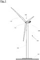
- FIG 1 shows a schematic representation of a wind energy installation 100.
- the wind energy installation 100 has a tower 102.
- the tower 102 is fastened to a base by means of a foundation 104.
- a gondola 106 is rotatably mounted on an end of the tower 102 opposite the subsurface.
- the nacelle 106 has, for example, a generator which is coupled to a rotor 108 via a rotor shaft (not shown).
- the rotor 108 has one or more (wind turbine) rotor blades 110 which are arranged on a rotor hub 112.
- the rotor 108 is set in rotation during operation by an air flow, for example wind. This rotational movement is transmitted to the generator via the rotor shaft and, if necessary, a gearbox. The generator converts the kinetic energy of the rotor 108 into electrical energy.
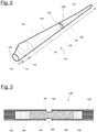
- FIG. 2 shows an exemplary wind turbine rotor blade 110.
- the rotor blade 110 has the shape of a conventional rotor blade and has a rotor blade root region 114 which faces the rotor hub 112.
- the rotor blade root region 114 typically has a substantially circular cross section.
- a transition area 116 and a profile area 118 of the rotor blade 110 adjoin the rotor blade root area 114.
- the rotor blade 110 has a pressure side 122 and an opposite suction side 124 with respect to a longitudinal extension direction 120 (also main extension direction).
- the rotor blade 110 is essentially hollow on the inside.
- a rotor blade connection end 126 with a flange connection 128 is located in the rotor blade root region 114 provided, by means of which the rotor blade 110 is mechanically connected to a pitch bearing or an extender.
- the rotor blade 110 has a dividing point 130 at which a blade root-side rotor blade segment 132 and a blade tip-side rotor blade segment 134 are connected to one another.
- the two segments 132, 134 each have a segment connection area 136, 138 (also connection ends).
- the rotor blade 110 is thus a divided rotor blade as described above.
- Each connection end 136, 138 has a multiplicity of bearing sleeves 140, 142 which are arranged following the profile and have internal threads for receiving screw bolts, also called bearing bolts or connecting bolts.
- the first bearing sleeves 140 have left-hand threads (first internal threads) and the second bearing sleeves 142 have right-hand threads (second internal threads) or vice versa.
- connection end 136, 138 is implemented, for example, as a flange insert, which is inserted as an insert into a production mold for producing the rotor blade 110.
- a connection end 136, 138 is implemented, for example, as a flange insert, which is inserted as an insert into a production mold for producing the rotor blade 110.
- no flange insert is provided and the bearing sleeves are embedded and laminated directly into the rotor blade half-shells.
- the bearing sleeves are, for example, steel sleeves.
- connection between the two rotor blade segments 132, 134 is described in more detail below, this being explained by way of example using a single bolt connection.
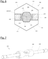
- Figure 3 shows a schematic sectional view in a partial area of two connected rotor blade segments 132, 134 at the dividing point 130, with a single bolt connection 148 is shown.
- the first connection end 136 of the first rotor blade segment 132 has a multiplicity of first bearing sleeves 140, as described above.
- the second connection end 138 of the second rotor blade segment 134 has a multiplicity of second bearing sleeves 142.
- a connecting bolt 146 is screwed into a pair of first and second bearing sleeves 140, 142 that are aligned with one another and mechanically firmly connects the two connection ends 136, 138 and thus the two rotor blade segments 132, 134.
- a pressure piece 144 is clamped between the two connection ends 136, 138 for each bolt connection 148.
- Figures 4 to 8 illustrate an exemplary embodiment of a kit 150 for a bolt connection 148 for connecting the two rotor blade segments 132, 134 according to an exemplary embodiment of the invention.
- the kit 150 comprises a connecting bolt 146, a pressure piece 144 and two mounting pieces 152.
- the connecting bolt 146 has a (central) longitudinal axis 154.
- the connecting bolt 146 each has an external thread 156 at opposite ends with respect to the longitudinal axis 154.
- the two external threads 156 are designed to correspond to the internal threads of the bearing sleeves 140, 142, for example differently, one external thread 156 being a right-hand thread and the other external thread 156 being a left-hand thread.
- the connecting bolt 146 has a mounting section 158 along the longitudinal axis 154, which in the exemplary embodiment is arranged approximately centrally with respect to both ends. in the In the assembly section 158, the connecting bolt 146 has a hexagon 160 or the connecting bolt 146 is hexagonal.
- the mounting section 158 is the area in which screw forces are transmitted to the connecting bolt 146.
- the pressure piece 144 is designed as a cylindrical sleeve and made from a simple semi-finished pipe product.
- the pressure piece 144 has a (central) longitudinal axis 145 and a continuous bore 162 (generally an opening).
- the bore 162 is designed in such a way that a minimum opening diameter is always larger than a maximum outside diameter of the connecting bolt 146, at least in the area of the mounting section 158.
- the pressure piece 144 is designed such that it can be pushed onto the connecting bolt 146.
- the pressure piece 144 has two recesses 164 evenly distributed over the circumference.
- the two mounting pieces 152 are designed such that they can each be inserted in a detachable form-fitting manner into a recess 164, so that there is only one degree of freedom in the radial direction with respect to the longitudinal axis 154.
- the assembly pieces 152 can be removed from the recesses 164 again.
- Each assembly piece 152 is designed to enter into a form fit with the connecting bolt 146 in the inserted state.
- the mounting piece 152 is provided on the side facing the connecting bolt 146 with a groove 166 which can grip around the hexagon 160 of the connecting bolt 146 in a form-fitting manner.
- the assembly pieces 152 are used to apply an assembly tool for screwing the connecting bolt 146, as will be explained below.
- Figure 5 shows an intended assembly state of the kit 150 for connecting the two rotor blade segments 132, 134 (not shown for reasons of clarity).
- the pressure piece 144 is pushed onto the connecting bolt 146 in such a way that the assembly section 158 of the connecting bolt 146 lies in the region of the recesses 164.
- the two assembly pieces 152 are inserted into the recesses 164, so that the form-fitting connections described above to the pressure piece 144 on the one hand and the connecting bolt 146 on the other hand are given.
- Figure 6 shows schematically a cross section along a cutting plane 168 (see Figure 5 ) in the intended assembly state of the kit 150.
- the grooves 166 of the assembly pieces 152 engage with fitting surfaces 170 around the hexagon 160 of the connecting bolt 146 in a form-fitting manner.
- the mounting pieces 152 themselves are designed in the manner of a hexagon on their outer sides and each have two corresponding tool application surfaces 172 that run at an angle to one another.
- a corresponding assembly tool such as a hydraulic clamping tool, is now attached to the tool engagement surfaces 172 in the assembly state shown.
- the assembly tool particularly engages around the assembly pieces 152 in a form-fitting manner, so that the assembly pieces 152 and thus the pressure piece 144 are set in rotation about the longitudinal axis 145 and 154, respectively. Due to the positive fit of the mounting pieces 152 with the connecting bolt 146, the latter is set in rotation and screwed or screwed with the external threads 156 into the internal threads of the bearing sleeves 140, 142, respectively braced, so that in particular the pressure piece 144 is braced between the two rotor blade segments 132, 134.
- Figure 7 shows an intended installation state of the kit 150, in which the two rotor blade segments 132, 134 are firmly connected to one another (not shown for reasons of clarity).
- the assembly pieces 152 are removed again from the recesses 164 of the pressure piece 144 and can be reused for a further bolt connection 148.
- Figure 8 shows a sectional view along the sectional plane 168 in the installed state with the assembly pieces 152 removed. It can be clearly seen that there is no contact between the connecting bolt 146 and the pressure piece 144. Rather, a gap 174 is formed between the connecting bolt 146 and the pressure piece 144 (see also Figure 6 ).
- a rotor blade segment for example the first rotor blade segment 132, is in an initial situation.
- the kit 150 is provided.
- a second step S2 the connecting bolt 146 is partially inserted into a first internal thread of the first connection end 136 of the first rotor blade segment 132 screwed in so that the connecting bolt 146 protrudes from the first connection end 136.
- step S4 the second connection end 138 of the second rotor blade segment 134 is brought up to the first connection end 136 of the first rotor blade segment 132.
- a next step S5 the connecting bolt 146 is partially screwed into a second internal thread of the second connection end 138 that corresponds to the first internal thread.
- the pressure piece 144 is arranged in such a way that the recesses 164 lie in the area of the mounting section 158 of the connecting bolt 146.
- a next step S6 the assembly pieces 152 are inserted into the recesses 164, so that they are each engaged with the connecting bolt 146 in a form-fitting manner and with the pressure piece 144 in a form-fitting manner.
- a next step S7 an assembly tool is attached to the assembly pieces 152 and / or the pressure piece 144 in a form-fitting manner and the connecting bolt 146 and the pressure piece 144 are screwed or clamped as described above.
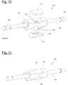
- Figures 10 and 11 show a second embodiment of a kit 150 for connecting two rotor blade segments 132, 134 in an exploded view.
- the kit 150 is essentially the same as the kit described in accordance with FIG Figures 4 to 8 .
- both the pressure piece 144 itself and the assembly pieces 152 are designed in the shape of a hexagon.
- the pressure piece 144 and the assembly pieces 152 are designed with regard to their external shape in such a way that the assembly pieces 152 are received flush in the recesses 164 in the assembled state (see the intended assembly state according to FIG Figure 11 ).
- the pressure piece 144 and the mounting pieces 152 thus form a common outer contour, the Mounting pieces 152 in particular do not protrude beyond the outer dimensions of the pressure piece 144 (in the radial direction with respect to the longitudinal axis 145).
- Figures 12 to 14 show a further exemplary embodiment of a kit 150 which essentially corresponds to the exemplary embodiments already described. In contrast to the above, a so-called tongue and groove connection is implemented with three mounting pieces 152.
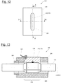
- Figure 12 shows a schematic plan view of the kit 150 in the intended assembly state, with no connecting bolt 146 being shown.
- a pressure piece 144 and a feather key 176 can be seen as an assembly piece 152.
- FIG. 13 shows a schematic longitudinal sectional view of the kit 150 according to the section plane AA of FIG Figure 12 .
- Figure 14 shows a schematic cross section of the kit 150 according to the section plane BB of FIG Figure 12 .
- the connecting bolt 146 is shown.
- three feather keys 176 are provided as mounting pieces 152 to be detachably mounted. In the assembled state, the feather keys 176 are evenly distributed over the circumference of the pressure piece 144 in correspondingly shaped recesses 164 of the pressure piece 144 and are releasably positively inserted.
- the feather keys 176 are connected to the connecting bolt 146 in a form-fitting manner in a manner similar to above in the assembly section 158. For this purpose, the feather keys 176 engage in correspondingly shaped grooves 166 of the connecting bolt 146.
- the connecting bolt 146 in the mounting section 158 is therefore not shaped like a hexagon.
- the parallel keys 176 each have a tool engagement surface 172 and are designed in such a way that a corresponding hexagonal assembly tool 180 (see FIG Figure 14 ) can start.
- screwing of the bolt 146 is again made possible via the assembly pieces 152, that is to say the feather keys 176.
- the feather keys 176 can again be removed so that the pressure piece 144 is mechanically decoupled from the bolt 146.
- the mounting pieces 152 optionally have one or more magnets 178, by means of which the mounting pieces 152 adhere to the connecting bolt 146.
- the adhesive force is such that a simple falling out of the assembly pieces 152 from the pressure pieces 144 is prevented, the detachability of the assembly pieces 152 while releasing the magnetic adhesive force is nevertheless ensured.
- the feather keys 176 optionally have an anti-loss device 182.
- the feather keys 176 are connected to the assembly tool 180 via a cable connection so that they are not lost or out of reach when they are released from the pressure piece 144 for a further assembly of another bolt connection 148.
- the pressure piece 144 optionally has a centering means 184 in the form of a centering sleeve or a centering ring, as described above.
- Figure 15 shows in one too Figure 14 analogous view of a further exemplary embodiment of a kit 150, which is shown in FIG Essentially according to the example Figures 12 to 14 is equivalent to.
- the feather keys 176 each have two tool engagement surfaces 172 which are arranged at an angle to one another, which are adapted to corners of a corresponding hexagonal assembly tool 180 and which engage in these for screwing the bolt 146.
- kits 150 of the described exemplary embodiments have in common is that two or more assembly pieces 152 are provided, which are inserted into recesses 164 of a pressure piece 144, so that both a positive connection to the pressure piece 144 and to the connecting bolt 146 is established.
- the assembly pieces 152 are releasably assembled and can easily be removed from the recesses 164 again.
- mounting pieces 152 and corresponding recesses 164 are also provided in alternative exemplary embodiments. It should also be mentioned that other shapes are conceivable for the connecting bolts 146 in the assembly section 185, the pressure pieces 144 and / or the assembly pieces 152, as long as corresponding positive connections are enabled that ensure the assembly and functionalities described. It should also be mentioned that all the features of the kits 150 described can be combined in accordance with the exemplary embodiments. For example, the mounting pieces 152 of the exemplary embodiments according to FIGS Figures 1 to 8, 10 and 11 Magnets conceivable.
Landscapes
- Engineering & Computer Science (AREA)
- Life Sciences & Earth Sciences (AREA)
- Sustainable Development (AREA)
- Sustainable Energy (AREA)
- Chemical & Material Sciences (AREA)
- Combustion & Propulsion (AREA)
- Mechanical Engineering (AREA)
- General Engineering & Computer Science (AREA)
- Wind Motors (AREA)
Priority Applications (3)
| Application Number | Priority Date | Filing Date | Title |
|---|---|---|---|
| ES20181436T ES2946911T3 (es) | 2020-06-22 | 2020-06-22 | Ensamble y procedimiento para conectar dos segmentos de hoja de rotor de una hoja de rotor de planta de energía eólica |
| EP20181436.5A EP3929431B1 (fr) | 2020-06-22 | 2020-06-22 | Module et procédé de raccordement de deux segments de pale de rotor d'une pale de rotor d'éolienne |
| DK20181436.5T DK3929431T3 (da) | 2020-06-22 | 2020-06-22 | Kit og fremgangsmåde til at forbinde to vindenergianlægsrotorblads rotorbladssegmenter |
Applications Claiming Priority (1)
| Application Number | Priority Date | Filing Date | Title |
|---|---|---|---|
| EP20181436.5A EP3929431B1 (fr) | 2020-06-22 | 2020-06-22 | Module et procédé de raccordement de deux segments de pale de rotor d'une pale de rotor d'éolienne |
Publications (2)
| Publication Number | Publication Date |
|---|---|
| EP3929431A1 true EP3929431A1 (fr) | 2021-12-29 |
| EP3929431B1 EP3929431B1 (fr) | 2023-03-22 |
Family
ID=71120116
Family Applications (1)
| Application Number | Title | Priority Date | Filing Date |
|---|---|---|---|
| EP20181436.5A Active EP3929431B1 (fr) | 2020-06-22 | 2020-06-22 | Module et procédé de raccordement de deux segments de pale de rotor d'une pale de rotor d'éolienne |
Country Status (3)
| Country | Link |
|---|---|
| EP (1) | EP3929431B1 (fr) |
| DK (1) | DK3929431T3 (fr) |
| ES (1) | ES2946911T3 (fr) |
Cited By (3)
| Publication number | Priority date | Publication date | Assignee | Title |
|---|---|---|---|---|
| WO2023169677A1 (fr) * | 2022-03-10 | 2023-09-14 | Nordex Energy Se & Co. Kg | Pale de rotor d'éolienne et procédé d'assemblage de deux segments de pale de rotor |
| WO2024000905A1 (fr) * | 2022-06-30 | 2024-01-04 | 江苏金风科技有限公司 | Pale et ensemble générateur éolien |
| DE102023135559A1 (de) * | 2023-12-18 | 2025-06-18 | Nordex Energy Se & Co. Kg | Verfahren zum Verbinden zweier Rotorblattsegmente eines Windenergieanlagenrotorblatts |
Families Citing this family (1)
| Publication number | Priority date | Publication date | Assignee | Title |
|---|---|---|---|---|
| WO2025103562A1 (fr) * | 2023-11-13 | 2025-05-22 | Adc Connection Solutions Gmbh | Dispositif et procédé de compensation de tolérances d'ensembles de liaison précontraints |
Citations (6)
| Publication number | Priority date | Publication date | Assignee | Title |
|---|---|---|---|---|
| JP2006329109A (ja) * | 2005-05-27 | 2006-12-07 | Fuji Heavy Ind Ltd | 水平軸風車のブレード |
| EP2199604A2 (fr) * | 2008-12-18 | 2010-06-23 | General Electric Company | Un module d'une pale du rotor, une pale du rotor modulaire et une méthode d'assemblage d'une pale du rotor modulaire |
| WO2015124568A1 (fr) | 2014-02-18 | 2015-08-27 | Lm Wp Patent Holding A/S | Système de manchon de pale de turbine éolienne |
| US20190032634A1 (en) * | 2016-04-04 | 2019-01-31 | Nabrawind Technologies SL | Apparatus for joining a modular blade |
| DE102018108695A1 (de) * | 2018-04-12 | 2019-10-17 | Wobben Properties Gmbh | Windenergieanlagen-Rotorblatt und Windenergieanlage |
| EP3581790A1 (fr) * | 2018-06-14 | 2019-12-18 | Siemens Gamesa Renewable Energy A/S | Pale de rotor d'éolienne |
-
2020
- 2020-06-22 EP EP20181436.5A patent/EP3929431B1/fr active Active
- 2020-06-22 ES ES20181436T patent/ES2946911T3/es active Active
- 2020-06-22 DK DK20181436.5T patent/DK3929431T3/da active
Patent Citations (6)
| Publication number | Priority date | Publication date | Assignee | Title |
|---|---|---|---|---|
| JP2006329109A (ja) * | 2005-05-27 | 2006-12-07 | Fuji Heavy Ind Ltd | 水平軸風車のブレード |
| EP2199604A2 (fr) * | 2008-12-18 | 2010-06-23 | General Electric Company | Un module d'une pale du rotor, une pale du rotor modulaire et une méthode d'assemblage d'une pale du rotor modulaire |
| WO2015124568A1 (fr) | 2014-02-18 | 2015-08-27 | Lm Wp Patent Holding A/S | Système de manchon de pale de turbine éolienne |
| US20190032634A1 (en) * | 2016-04-04 | 2019-01-31 | Nabrawind Technologies SL | Apparatus for joining a modular blade |
| DE102018108695A1 (de) * | 2018-04-12 | 2019-10-17 | Wobben Properties Gmbh | Windenergieanlagen-Rotorblatt und Windenergieanlage |
| EP3581790A1 (fr) * | 2018-06-14 | 2019-12-18 | Siemens Gamesa Renewable Energy A/S | Pale de rotor d'éolienne |
Cited By (3)
| Publication number | Priority date | Publication date | Assignee | Title |
|---|---|---|---|---|
| WO2023169677A1 (fr) * | 2022-03-10 | 2023-09-14 | Nordex Energy Se & Co. Kg | Pale de rotor d'éolienne et procédé d'assemblage de deux segments de pale de rotor |
| WO2024000905A1 (fr) * | 2022-06-30 | 2024-01-04 | 江苏金风科技有限公司 | Pale et ensemble générateur éolien |
| DE102023135559A1 (de) * | 2023-12-18 | 2025-06-18 | Nordex Energy Se & Co. Kg | Verfahren zum Verbinden zweier Rotorblattsegmente eines Windenergieanlagenrotorblatts |
Also Published As
| Publication number | Publication date |
|---|---|
| DK3929431T3 (da) | 2023-06-26 |
| ES2946911T3 (es) | 2023-07-27 |
| EP3929431B1 (fr) | 2023-03-22 |
Similar Documents
| Publication | Publication Date | Title |
|---|---|---|
| EP4038271B1 (fr) | Pale de rotor d'éolienne et procédé de liaison de deux segments de pale de rotor | |
| EP1398499B1 (fr) | Fixation des aubes sur le moyeu d'éolienne | |
| EP3929431B1 (fr) | Module et procédé de raccordement de deux segments de pale de rotor d'une pale de rotor d'éolienne | |
| EP2788617B1 (fr) | Pale de rotor et dispositif d'assemblage | |
| EP1975405B1 (fr) | Raccordement des éléments d'une installation d'énergie éolienne, utilization et procédé | |
| EP2283231B2 (fr) | Procédé de fabrication d'un raccord de pale de rotor, raccord de pale et élément de fixation pour un raccord de pale | |
| EP2126353B1 (fr) | Assemblage de composants d'une éolienne et procédé | |
| EP2420670B1 (fr) | Dispositif de verrouillage de rotor et procédé d'arrêt d'un rotor d'une éolienne | |
| EP2154367B1 (fr) | Procédé de montage d'un moyeu d'hélice sur un arbre de rotor d'une éolienne et éolienne | |
| EP3855014B1 (fr) | Pale de rotor divisée d'une éolienne ainsi que segment de pale de rotor | |
| DE102011002488A1 (de) | Anordnung von Bauteilen einer Windenergieanlage | |
| DE102010046518A1 (de) | Rotorblatt oder Rotorsegment für eine Windenergieanlage | |
| EP3559417B1 (fr) | Procédé de fabrication d'une pale de rotor d'éolienne et pale de rotor d'éolienne | |
| DE102017106875B4 (de) | Windkraftanlage und Verfahren zu dessen Montage | |
| EP3204633B1 (fr) | Pale de rotor d'éolienne | |
| EP4155530A1 (fr) | Pale de rotor pour éolienne et procédé de montage d'une pale de rotor pour éolienne | |
| DE102016123346B3 (de) | Faserverbundbauteil, Faserverbundstruktur und Herstellung derselben | |
| EP2365209A2 (fr) | Roue de turbine dotée d'ailettes reliées par complémentarité de forme et de force | |
| EP4400712A1 (fr) | Insert pour une pale de rotor d'éolienne et pale de rotor d'éolienne | |
| EP3710691B1 (fr) | Attachement d'une pale d'éolienne avec le moyeu d'une éolienne | |
| EP4400713A1 (fr) | Pale de rotor d'éolienne divisée et procédé de liaison de deux segments de pale de rotor d'une pale de rotor d'éolienne | |
| EP3653872A1 (fr) | Procédé de fabrication de deux segments de pale de rotor, segment de pale de rotor ainsi que pale de rotor divisée | |
| DE102023135559A1 (de) | Verfahren zum Verbinden zweier Rotorblattsegmente eines Windenergieanlagenrotorblatts | |
| DE102017126970A1 (de) | Rotorblatt und Rotor für eine Windenergieanlage, Windenergieanlage, Verfahren zur Herstellung eines Rotorblatts, zur Verbindung eines Rotorblatts mit einer Rotornabe und zur Reparatur eines Rotors einer Windenergieanlage |
Legal Events
| Date | Code | Title | Description |
|---|---|---|---|
| PUAI | Public reference made under article 153(3) epc to a published international application that has entered the european phase |
Free format text: ORIGINAL CODE: 0009012 |
|
| STAA | Information on the status of an ep patent application or granted ep patent |
Free format text: STATUS: THE APPLICATION HAS BEEN PUBLISHED |
|
| AK | Designated contracting states |
Kind code of ref document: A1 Designated state(s): AL AT BE BG CH CY CZ DE DK EE ES FI FR GB GR HR HU IE IS IT LI LT LU LV MC MK MT NL NO PL PT RO RS SE SI SK SM TR |
|
| B565 | Issuance of search results under rule 164(2) epc |
Effective date: 20201207 |
|
| STAA | Information on the status of an ep patent application or granted ep patent |
Free format text: STATUS: REQUEST FOR EXAMINATION WAS MADE |
|
| RIN1 | Information on inventor provided before grant (corrected) |
Inventor name: WERNER, MARKUS Inventor name: LIPKA, THOMAS |
|
| 17P | Request for examination filed |
Effective date: 20220516 |
|
| RBV | Designated contracting states (corrected) |
Designated state(s): AL AT BE BG CH CY CZ DE DK EE ES FI FR GB GR HR HU IE IS IT LI LT LU LV MC MK MT NL NO PL PT RO RS SE SI SK SM TR |
|
| GRAP | Despatch of communication of intention to grant a patent |
Free format text: ORIGINAL CODE: EPIDOSNIGR1 |
|
| STAA | Information on the status of an ep patent application or granted ep patent |
Free format text: STATUS: GRANT OF PATENT IS INTENDED |
|
| RIC1 | Information provided on ipc code assigned before grant |
Ipc: F03D 13/10 20160101ALI20220906BHEP Ipc: F03D 1/06 20060101AFI20220906BHEP |
|
| INTG | Intention to grant announced |
Effective date: 20221010 |
|
| GRAS | Grant fee paid |
Free format text: ORIGINAL CODE: EPIDOSNIGR3 |
|
| GRAA | (expected) grant |
Free format text: ORIGINAL CODE: 0009210 |
|
| STAA | Information on the status of an ep patent application or granted ep patent |
Free format text: STATUS: THE PATENT HAS BEEN GRANTED |
|
| AK | Designated contracting states |
Kind code of ref document: B1 Designated state(s): AL AT BE BG CH CY CZ DE DK EE ES FI FR GB GR HR HU IE IS IT LI LT LU LV MC MK MT NL NO PL PT RO RS SE SI SK SM TR |
|
| REG | Reference to a national code |
Ref country code: GB Ref legal event code: FG4D Free format text: NOT ENGLISH |
|
| REG | Reference to a national code |
Ref country code: CH Ref legal event code: EP |
|
| REG | Reference to a national code |
Ref country code: DE Ref legal event code: R096 Ref document number: 502020002782 Country of ref document: DE |
|
| REG | Reference to a national code |
Ref country code: IE Ref legal event code: FG4D Free format text: LANGUAGE OF EP DOCUMENT: GERMAN |
|
| REG | Reference to a national code |
Ref country code: AT Ref legal event code: REF Ref document number: 1555432 Country of ref document: AT Kind code of ref document: T Effective date: 20230415 |
|
| P01 | Opt-out of the competence of the unified patent court (upc) registered |
Effective date: 20230515 |
|
| REG | Reference to a national code |
Ref country code: DK Ref legal event code: T3 Effective date: 20230623 |
|
| REG | Reference to a national code |
Ref country code: LT Ref legal event code: MG9D |
|
| REG | Reference to a national code |
Ref country code: NL Ref legal event code: MP Effective date: 20230322 |
|
| REG | Reference to a national code |
Ref country code: ES Ref legal event code: FG2A Ref document number: 2946911 Country of ref document: ES Kind code of ref document: T3 Effective date: 20230727 |
|
| PG25 | Lapsed in a contracting state [announced via postgrant information from national office to epo] |
Ref country code: RS Free format text: LAPSE BECAUSE OF FAILURE TO SUBMIT A TRANSLATION OF THE DESCRIPTION OR TO PAY THE FEE WITHIN THE PRESCRIBED TIME-LIMIT Effective date: 20230322 Ref country code: NO Free format text: LAPSE BECAUSE OF FAILURE TO SUBMIT A TRANSLATION OF THE DESCRIPTION OR TO PAY THE FEE WITHIN THE PRESCRIBED TIME-LIMIT Effective date: 20230622 Ref country code: LV Free format text: LAPSE BECAUSE OF FAILURE TO SUBMIT A TRANSLATION OF THE DESCRIPTION OR TO PAY THE FEE WITHIN THE PRESCRIBED TIME-LIMIT Effective date: 20230322 Ref country code: LT Free format text: LAPSE BECAUSE OF FAILURE TO SUBMIT A TRANSLATION OF THE DESCRIPTION OR TO PAY THE FEE WITHIN THE PRESCRIBED TIME-LIMIT Effective date: 20230322 Ref country code: HR Free format text: LAPSE BECAUSE OF FAILURE TO SUBMIT A TRANSLATION OF THE DESCRIPTION OR TO PAY THE FEE WITHIN THE PRESCRIBED TIME-LIMIT Effective date: 20230322 |
|
| PG25 | Lapsed in a contracting state [announced via postgrant information from national office to epo] |
Ref country code: SE Free format text: LAPSE BECAUSE OF FAILURE TO SUBMIT A TRANSLATION OF THE DESCRIPTION OR TO PAY THE FEE WITHIN THE PRESCRIBED TIME-LIMIT Effective date: 20230322 Ref country code: NL Free format text: LAPSE BECAUSE OF FAILURE TO SUBMIT A TRANSLATION OF THE DESCRIPTION OR TO PAY THE FEE WITHIN THE PRESCRIBED TIME-LIMIT Effective date: 20230322 Ref country code: GR Free format text: LAPSE BECAUSE OF FAILURE TO SUBMIT A TRANSLATION OF THE DESCRIPTION OR TO PAY THE FEE WITHIN THE PRESCRIBED TIME-LIMIT Effective date: 20230623 Ref country code: FI Free format text: LAPSE BECAUSE OF FAILURE TO SUBMIT A TRANSLATION OF THE DESCRIPTION OR TO PAY THE FEE WITHIN THE PRESCRIBED TIME-LIMIT Effective date: 20230322 |
|
| PG25 | Lapsed in a contracting state [announced via postgrant information from national office to epo] |
Ref country code: SM Free format text: LAPSE BECAUSE OF FAILURE TO SUBMIT A TRANSLATION OF THE DESCRIPTION OR TO PAY THE FEE WITHIN THE PRESCRIBED TIME-LIMIT Effective date: 20230322 Ref country code: RO Free format text: LAPSE BECAUSE OF FAILURE TO SUBMIT A TRANSLATION OF THE DESCRIPTION OR TO PAY THE FEE WITHIN THE PRESCRIBED TIME-LIMIT Effective date: 20230322 Ref country code: PT Free format text: LAPSE BECAUSE OF FAILURE TO SUBMIT A TRANSLATION OF THE DESCRIPTION OR TO PAY THE FEE WITHIN THE PRESCRIBED TIME-LIMIT Effective date: 20230724 Ref country code: EE Free format text: LAPSE BECAUSE OF FAILURE TO SUBMIT A TRANSLATION OF THE DESCRIPTION OR TO PAY THE FEE WITHIN THE PRESCRIBED TIME-LIMIT Effective date: 20230322 |
|
| PG25 | Lapsed in a contracting state [announced via postgrant information from national office to epo] |
Ref country code: SK Free format text: LAPSE BECAUSE OF FAILURE TO SUBMIT A TRANSLATION OF THE DESCRIPTION OR TO PAY THE FEE WITHIN THE PRESCRIBED TIME-LIMIT Effective date: 20230322 Ref country code: PL Free format text: LAPSE BECAUSE OF FAILURE TO SUBMIT A TRANSLATION OF THE DESCRIPTION OR TO PAY THE FEE WITHIN THE PRESCRIBED TIME-LIMIT Effective date: 20230322 Ref country code: IS Free format text: LAPSE BECAUSE OF FAILURE TO SUBMIT A TRANSLATION OF THE DESCRIPTION OR TO PAY THE FEE WITHIN THE PRESCRIBED TIME-LIMIT Effective date: 20230722 |
|
| REG | Reference to a national code |
Ref country code: DE Ref legal event code: R097 Ref document number: 502020002782 Country of ref document: DE |
|
| PG25 | Lapsed in a contracting state [announced via postgrant information from national office to epo] |
Ref country code: MC Free format text: LAPSE BECAUSE OF FAILURE TO SUBMIT A TRANSLATION OF THE DESCRIPTION OR TO PAY THE FEE WITHIN THE PRESCRIBED TIME-LIMIT Effective date: 20230322 |
|
| PLBE | No opposition filed within time limit |
Free format text: ORIGINAL CODE: 0009261 |
|
| STAA | Information on the status of an ep patent application or granted ep patent |
Free format text: STATUS: NO OPPOSITION FILED WITHIN TIME LIMIT |
|
| PG25 | Lapsed in a contracting state [announced via postgrant information from national office to epo] |
Ref country code: SI Free format text: LAPSE BECAUSE OF FAILURE TO SUBMIT A TRANSLATION OF THE DESCRIPTION OR TO PAY THE FEE WITHIN THE PRESCRIBED TIME-LIMIT Effective date: 20230322 Ref country code: MC Free format text: LAPSE BECAUSE OF FAILURE TO SUBMIT A TRANSLATION OF THE DESCRIPTION OR TO PAY THE FEE WITHIN THE PRESCRIBED TIME-LIMIT Effective date: 20230322 Ref country code: CZ Free format text: LAPSE BECAUSE OF FAILURE TO SUBMIT A TRANSLATION OF THE DESCRIPTION OR TO PAY THE FEE WITHIN THE PRESCRIBED TIME-LIMIT Effective date: 20230322 |
|
| REG | Reference to a national code |
Ref country code: CH Ref legal event code: PL |
|
| REG | Reference to a national code |
Ref country code: BE Ref legal event code: MM Effective date: 20230630 |
|
| 26N | No opposition filed |
Effective date: 20240102 |
|
| PG25 | Lapsed in a contracting state [announced via postgrant information from national office to epo] |
Ref country code: LU Free format text: LAPSE BECAUSE OF NON-PAYMENT OF DUE FEES Effective date: 20230622 |
|
| REG | Reference to a national code |
Ref country code: IE Ref legal event code: MM4A |
|
| PG25 | Lapsed in a contracting state [announced via postgrant information from national office to epo] |
Ref country code: LU Free format text: LAPSE BECAUSE OF NON-PAYMENT OF DUE FEES Effective date: 20230622 |
|
| PG25 | Lapsed in a contracting state [announced via postgrant information from national office to epo] |
Ref country code: IE Free format text: LAPSE BECAUSE OF NON-PAYMENT OF DUE FEES Effective date: 20230622 |
|
| PG25 | Lapsed in a contracting state [announced via postgrant information from national office to epo] |
Ref country code: IE Free format text: LAPSE BECAUSE OF NON-PAYMENT OF DUE FEES Effective date: 20230622 Ref country code: CH Free format text: LAPSE BECAUSE OF NON-PAYMENT OF DUE FEES Effective date: 20230630 |
|
| PG25 | Lapsed in a contracting state [announced via postgrant information from national office to epo] |
Ref country code: IT Free format text: LAPSE BECAUSE OF FAILURE TO SUBMIT A TRANSLATION OF THE DESCRIPTION OR TO PAY THE FEE WITHIN THE PRESCRIBED TIME-LIMIT Effective date: 20230322 Ref country code: FR Free format text: LAPSE BECAUSE OF NON-PAYMENT OF DUE FEES Effective date: 20230630 Ref country code: BE Free format text: LAPSE BECAUSE OF NON-PAYMENT OF DUE FEES Effective date: 20230630 |
|
| PG25 | Lapsed in a contracting state [announced via postgrant information from national office to epo] |
Ref country code: BG Free format text: LAPSE BECAUSE OF FAILURE TO SUBMIT A TRANSLATION OF THE DESCRIPTION OR TO PAY THE FEE WITHIN THE PRESCRIBED TIME-LIMIT Effective date: 20230322 |
|
| PG25 | Lapsed in a contracting state [announced via postgrant information from national office to epo] |
Ref country code: BG Free format text: LAPSE BECAUSE OF FAILURE TO SUBMIT A TRANSLATION OF THE DESCRIPTION OR TO PAY THE FEE WITHIN THE PRESCRIBED TIME-LIMIT Effective date: 20230322 |
|
| GBPC | Gb: european patent ceased through non-payment of renewal fee |
Effective date: 20240622 |
|
| PG25 | Lapsed in a contracting state [announced via postgrant information from national office to epo] |
Ref country code: GB Free format text: LAPSE BECAUSE OF NON-PAYMENT OF DUE FEES Effective date: 20240622 |
|
| PGFP | Annual fee paid to national office [announced via postgrant information from national office to epo] |
Ref country code: DE Payment date: 20250618 Year of fee payment: 6 |
|
| PGFP | Annual fee paid to national office [announced via postgrant information from national office to epo] |
Ref country code: DK Payment date: 20250618 Year of fee payment: 6 |
|
| PGFP | Annual fee paid to national office [announced via postgrant information from national office to epo] |
Ref country code: AT Payment date: 20250721 Year of fee payment: 5 |
|
| PG25 | Lapsed in a contracting state [announced via postgrant information from national office to epo] |
Ref country code: CY Free format text: LAPSE BECAUSE OF FAILURE TO SUBMIT A TRANSLATION OF THE DESCRIPTION OR TO PAY THE FEE WITHIN THE PRESCRIBED TIME-LIMIT; INVALID AB INITIO Effective date: 20200622 |
|
| PG25 | Lapsed in a contracting state [announced via postgrant information from national office to epo] |
Ref country code: HU Free format text: LAPSE BECAUSE OF FAILURE TO SUBMIT A TRANSLATION OF THE DESCRIPTION OR TO PAY THE FEE WITHIN THE PRESCRIBED TIME-LIMIT; INVALID AB INITIO Effective date: 20200622 |
|
| PGFP | Annual fee paid to national office [announced via postgrant information from national office to epo] |
Ref country code: ES Payment date: 20250718 Year of fee payment: 6 |
|
| PG25 | Lapsed in a contracting state [announced via postgrant information from national office to epo] |
Ref country code: TR Free format text: LAPSE BECAUSE OF FAILURE TO SUBMIT A TRANSLATION OF THE DESCRIPTION OR TO PAY THE FEE WITHIN THE PRESCRIBED TIME-LIMIT Effective date: 20230322 |