EP3825730A1 - Affectation de chaque point d'un nuage de points à une position de dispositif de balayage d'une pluralité de différentes positions de dispositif de balayage dans un nuage de points - Google Patents
Affectation de chaque point d'un nuage de points à une position de dispositif de balayage d'une pluralité de différentes positions de dispositif de balayage dans un nuage de points Download PDFInfo
- Publication number
- EP3825730A1 EP3825730A1 EP19306500.0A EP19306500A EP3825730A1 EP 3825730 A1 EP3825730 A1 EP 3825730A1 EP 19306500 A EP19306500 A EP 19306500A EP 3825730 A1 EP3825730 A1 EP 3825730A1
- Authority
- EP
- European Patent Office
- Prior art keywords
- point
- scanner
- point cloud
- disk
- output
- Prior art date
- Legal status (The legal status is an assumption and is not a legal conclusion. Google has not performed a legal analysis and makes no representation as to the accuracy of the status listed.)
- Withdrawn
Links
Images


Classifications
-
- G—PHYSICS
- G01—MEASURING; TESTING
- G01S—RADIO DIRECTION-FINDING; RADIO NAVIGATION; DETERMINING DISTANCE OR VELOCITY BY USE OF RADIO WAVES; LOCATING OR PRESENCE-DETECTING BY USE OF THE REFLECTION OR RERADIATION OF RADIO WAVES; ANALOGOUS ARRANGEMENTS USING OTHER WAVES
- G01S17/00—Systems using the reflection or reradiation of electromagnetic waves other than radio waves, e.g. lidar systems
- G01S17/88—Lidar systems specially adapted for specific applications
- G01S17/89—Lidar systems specially adapted for specific applications for mapping or imaging
-
- G—PHYSICS
- G01—MEASURING; TESTING
- G01S—RADIO DIRECTION-FINDING; RADIO NAVIGATION; DETERMINING DISTANCE OR VELOCITY BY USE OF RADIO WAVES; LOCATING OR PRESENCE-DETECTING BY USE OF THE REFLECTION OR RERADIATION OF RADIO WAVES; ANALOGOUS ARRANGEMENTS USING OTHER WAVES
- G01S7/00—Details of systems according to groups G01S13/00, G01S15/00, G01S17/00
- G01S7/48—Details of systems according to groups G01S13/00, G01S15/00, G01S17/00 of systems according to group G01S17/00
- G01S7/4808—Evaluating distance, position or velocity data
-
- G—PHYSICS
- G06—COMPUTING OR CALCULATING; COUNTING
- G06T—IMAGE DATA PROCESSING OR GENERATION, IN GENERAL
- G06T7/00—Image analysis
- G06T7/50—Depth or shape recovery
- G06T7/521—Depth or shape recovery from laser ranging, e.g. using interferometry; from the projection of structured light
-
- G—PHYSICS
- G06—COMPUTING OR CALCULATING; COUNTING
- G06T—IMAGE DATA PROCESSING OR GENERATION, IN GENERAL
- G06T7/00—Image analysis
- G06T7/60—Analysis of geometric attributes
-
- G—PHYSICS
- G06—COMPUTING OR CALCULATING; COUNTING
- G06T—IMAGE DATA PROCESSING OR GENERATION, IN GENERAL
- G06T7/00—Image analysis
- G06T7/70—Determining position or orientation of objects or cameras
- G06T7/73—Determining position or orientation of objects or cameras using feature-based methods
-
- G—PHYSICS
- G06—COMPUTING OR CALCULATING; COUNTING
- G06F—ELECTRIC DIGITAL DATA PROCESSING
- G06F16/00—Information retrieval; Database structures therefor; File system structures therefor
- G06F16/50—Information retrieval; Database structures therefor; File system structures therefor of still image data
- G06F16/58—Retrieval characterised by using metadata, e.g. metadata not derived from the content or metadata generated manually
- G06F16/583—Retrieval characterised by using metadata, e.g. metadata not derived from the content or metadata generated manually using metadata automatically derived from the content
-
- G—PHYSICS
- G06—COMPUTING OR CALCULATING; COUNTING
- G06T—IMAGE DATA PROCESSING OR GENERATION, IN GENERAL
- G06T2200/00—Indexing scheme for image data processing or generation, in general
- G06T2200/04—Indexing scheme for image data processing or generation, in general involving 3D image data
-
- G—PHYSICS
- G06—COMPUTING OR CALCULATING; COUNTING
- G06T—IMAGE DATA PROCESSING OR GENERATION, IN GENERAL
- G06T2207/00—Indexing scheme for image analysis or image enhancement
- G06T2207/10—Image acquisition modality
- G06T2207/10028—Range image; Depth image; 3D point clouds
-
- G—PHYSICS
- G06—COMPUTING OR CALCULATING; COUNTING
- G06T—IMAGE DATA PROCESSING OR GENERATION, IN GENERAL
- G06T2207/00—Indexing scheme for image analysis or image enhancement
- G06T2207/30—Subject of image; Context of image processing
- G06T2207/30244—Camera pose
Definitions
- the present disclosure relates generally to processing point clouds, and more specifically to assigning each point of a point cloud to a scanner position of a plurality of different scanner positions in the point cloud to process the point cloud.
- Particular applications may automatically generate a high-resolution 3D mesh of a scene from photographs and/or from one or more point clouds as captured by scanners, e.g., Light Detection and Ranging (LiDAR) scanners.
- scanners e.g., Light Detection and Ranging (LiDAR) scanners.
- the particular applications may need to know the position of each scanner in the environment, i.e., scene, and may also need visibility information for each point of the point cloud, e.g., which scanner has visibility to each point of the point cloud.
- the metadata which typical stores the visibility information, may not be provided with the file/object that stores point cloud (e.g., point cloud data). Therefore, and according to traditional techniques, the point cloud cannot be processed by the applications to generate the high-resolution 3D mesh of the scene because of the missing visibility information.
- a plurality of scanners such as LiDAR scanners, may scan a scene to capture a point cloud.
- a process may utilize the position information (e.g., x, y, and z coordinates) of the points of the point cloud and the positions (e.g., x, y, and z coordinates) of the scanners to assign each point of the point cloud to a scanner position of a plurality of different scanner positions in the point cloud according to one or more embodiments described herein.
- the process may compute a scale for each point of the point cloud based on a distance from the point to its N/2 closest neighbor.
- the scale may represent a local size of the point, which may be based on the size of the point's local neighborhood.
- N may be selected as a design parameter and may be a value such as, but not limited to, a number between 15 and 50.
- the process may apply a non-linear normalization by setting the bottom c% scales to the c th percentile value and by setting the top c% scales to the 100 -c th percentile value.
- the process may compute a non-orientated normal value utilizing a known principal component analysis (PCA) algorithm.
- PCA principal component analysis
- the process may then create a disk for each point of the point cloud, where a size of the disk is based on the computed scale for the point and the orientation of the disk in space is based on the computed non-orientated normal for the point.
- the center of the disk may lie at the position of the point (e.g., x, y, and z coordinates) and the radius of the disk may be the computed scale for the point.
- the non-oriented normal computed for the point may be used for orientating the disk in space.
- the process may then insert each disk, representing a different point of the point cloud, in a search structure that may be utilized for the efficient computation of the intersection of an input value with a set of objects.
- the search structure may be an Axis Aligned Bounding Box (AABB) tree (that is utilized to determine which disks, representing different points, intersect a segment (i.e., path) in space between a point and a particular scanner.
- AABB Axis Aligned Bounding Box
- the process may create L segments for a given point of the point cloud, where L is equal to the number of scanners in the point cloud and each of the L segments is a pair that includes the position of the given point and the position of a different scanner in the point cloud. That is, the L segments represent the paths in space between the position of the given point (e.g., x, y, and z coordinates) and each of the different scanner positions (e.g., x, y, and z, coordinates) in the point cloud.
- the process may then query the search structure, utilizing each of the L segments for the given point, to obtain the disks, if any, that intersect each segment, e.g., each path between the given point and a different scanner. Therefore, the process may obtain a listing of the one or more disks, if any, that intersect/occlude each path from the given point to a different scanner in the point cloud.
- the process may then create L outputs for the given point, where each output corresponds to a different scanner and includes at least the number, if any, of intersecting (i.e., occluding) disks in the path from the point to the different scanner, and the distance from the point to the different scanner.
- the process may then exclude particular disks, from the total number of disks for each of the L outputs, which are determined to be false positives, e.g., intersecting disks that may be created because of noise that may be inherent to point clouds captured by LiDAR scanners.
- the process may utilize the distances between a particular scanner and the given point, the distance between the given point and a particular intersecting disk, and the distance between the particular scanner and the particular intersecting disk to determine whether the particular disk is a false positive and should be excluded.
- the process may then adjust (e.g., decrease) the number of intersecting disks for the output based on the exclusion of a disk determined to be a false positive.
- the process may implement a sorting algorithm that compares the values in a plurality of the L outputs to identify a scanner, of the plurality of scanner in the point cloud, which has the best view of the given point (e.g., clearest line of sight with the least occlusions to the given point).
- the process may then assign the given point to the scanner position, i.e., the position of the scanner determined to have the best view of the given point.
- the process may assign each of the plurality of points of the point cloud, in parallel or serially, to a scanner position of a plurality of different scanner positions according to the one or more embodiments described herein.
- the process may create one or more data structures, e.g., one or more visibility data structures, which store the assignment of each point of the point cloud to a scanner position.
- the process may then orient the normal of each point based on a dot product of the computed non-oriented normal value for the point and the direction to the scanner position the point is assigned to. If the dot product is a positive value, then the orientation of the computed normal value is correct. However, if the dot product is a negative value, the process may invert the sign of computed normal value for the point.
- particular applications may process point clouds without the metadata that typically stores the visibility information.
- the application may receive the point cloud (i.e., point cloud data) captured for a scene from multiple scanners and may also obtain the positions of the multiple scanners.
- the application may process the point cloud, utilizing the assignment of each point of the point cloud to a scanner position performed according to the one or more embodiments described herein, to generate a high-resolution 3D mesh of the scene.
- the one or more embodiments described herein provide an improvement in the existing technological field of point cloud processing since the particular applications, which require the visibility information, can process point cloud utilizing the assignment of each point of the point cloud to a scanner position performed according to the one or more embodiments described herein.
- the one or more embodiments described herein have a practical application since the particular applications, which require that the visibility information, can process the point cloud with the assignment of each point of the point cloud to a scanner position performed according to the one or more embodiments described herein.
- Fig. 1 is a high-level block diagram of an example environment 100 according to one or more embodiments described herein.
- the environment 100 includes a plurality of scanners 105 and one or more end user computing devices 110 that may communicate via network 114.
- the scanners 105 may be, for example, LiDAR scanners, or other type of scanners that capture source data, such as a point cloud, that includes a plurality of points in space representing the external surfaces of objects in a scene in which the scanners 105 are located and operating.
- source data such as a point cloud
- Each end user computing device 110 in environment 100 may include processors, memory, storage systems, and other hardware (not shown).
- the one or more end user computing devices 110 may include one or more graphical user interfaces (GUIs) that allows a user to interact with an application 125 executing on the end user computing device 110.
- GUIs graphical user interfaces
- the application 125 may be, but is not limited to, 3D modeling software.
- the 3D modeling software may be the ContextCaptureTM application available from Bentley Systems, Inc., which processes point clouds to generate high-resolution 3D meshes of a scene.
- the application 125 may receive a file/object including the point cloud without visibility information from the scanners 105 over the network 114.
- the end user computing device 110 may receive the file/object including the point cloud without the visibility information in any of a variety of different ways.
- the file/object may be stored on a storage device (e.g., solid-state drive (SSD), hard drive, etc.) and transferred to the end user computing device 110.
- the application 125 may include visibility process 118 that implements one or more embodiments described herein. Specifically, visibility process 118 may assign each point of a point cloud to a scanner position of a plurality of different scanner positions in the point cloud.
- the end user computing device 110 may store visibility data structure(s) 800 that stores an assignment of each point of the point cloud to a scanner position according to the one or more embodiments described herein.
- the application 125 may utilize, for example, the assignment of each point of the point cloud to a scanner position to process a point cloud and generate a 3D mesh of a scene in which the scanners 105 are located and operating.
- Figs. 2A and 2B are a flow diagram of a sequence of steps for assigning each point of a point cloud to a scanner position of a plurality of different scanner positions in the point cloud according to one or more embodiments described herein.
- the examples described herein may refer to a point cloud including a particular number of scanners, however it expressly contemplated that the one or more embodiment described herein may assign each point of the point cloud to a scanner position in a point cloud having any number of scanners.
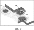
- Fig. 3 is a diagram illustrating an example scene in which scanners 105 are located and operating according to one or more embodiments described herein.
- Scanners 105 may operate in scene 300 that, for example, includes a plurality of objects (e.g., walls, ground, etc.).
- the scanners 105 may be a LiDAR scanner that captures a point cloud that includes a plurality of points in space representing the external surfaces of the objects in scene 300. For example, and as depicted in Fig.
- the point cloud captured from the scan of scene 300 by the scanners 105a, 105b, and 105c may include a plurality of points that each having a position (e.g., x, y, and z coordinates) relative to the scanners 105.
- each scanner, 105a, 105b, and 105c may be known and/or determined.
- the end user computing device 110 obtains the point cloud and the position of the scanners 105.
- the scanners 105a, 105b, and 105c may provide the point cloud to the end user computing device 110 over network 114.
- the end user computing device 110 may receive the point cloud in any of a variety of different ways.
- the point cloud may be stored on a storage device (e.g., solid-state drive (SSD), hard drive, etc.) and transferred to the end user computing device 110.
- SSD solid-state drive
- the end user computing device 110 may receive the point cloud without visibility information, e.g., which scanner has visibility to each point of the point cloud.
- the end user computing device 110 may receive or obtain (e.g., determine) the position of each scanner (e.g., 105a, 105b, and 105c) in the point cloud.
- the end user computing device 110 may receive the position of each scanner over the network 114 from the scanners (e.g., 105a, 105b, and 105c).
- the end user computing device 110 may receive the position of each scanner in any of a variety of different ways.
- the position of each scanner may be stored on a storage device and transferred to the end user computing device 110.
- the visibility process 118 computes a scale for each point of the point cloud.
- the visibility process may compute a scale for a point of the point cloud based on a distance from the point to its N/2 closest neighbor.
- the scale may represent a local size of the point, which may be based on the size of the point's local neighborhood.
- N may be selected as a design parameter and may be value such as, but not limited to, a number between 15 and 50. In an embodiment, N is 25.
- the visibility process 118 computes the distance from the point to its 25 th closest neighbor and divides that distance by 2 to compute the scale for the point.
- the visibility process 118 computes the scale for each point of the point cloud in a similar manner and according to one or more embodiments described herein.
- the visibility process 118 may apply a non-linear normalization by setting the bottom c% scales to the c th percentile value and by setting the top c% scales to the 100 - c th percentile value.
- c may be 5.
- the visibility process 118 may set the bottom 5% of the computed scale values to the 5 th percentile computed scale value, and may also set the top 5% of the computed scale values to the 95 th percentile computed scale value.
- the procedure continues to step 225 and the visibility process 118 may compute a non-oriented normal value for each point of the point cloud.
- the visibility process 118 may utilize a known principal component analysis (PCA) algorithm with parameters, e.g., number of neighboring points, to compute the non-oriented normal value for each point of the point cloud.
- PCA principal component analysis
- the procedure continues to step 230 and the visibility process creates a disk for each point of the point cloud.
- points of a point cloud are discreet information such that each point of the point cloud does not have a volume/area.
- the visibility process 118 may create a disk for each point of the point cloud.
- a coarse representation of the surface is created and that can be utilized to determine if the path between a point and a scanner is obstructed by the surface, as will be described in further detail below.
- the visibility process 118 may create a disk for each of the other points of the point cloud in a similar manner and according to one or more embodiments described herein.
- the procedure continues to step 235 and the visibility process 118 inserts each disk, created for and representing a different point of the point cloud, in a search structure that may be utilized for the efficient computation of the intersection of an input value with a set of objects.
- the search structure may be an axis aligned bounding box (AABB) tree that is utilized to determine which disks, representing different points, intersect a segment (i.e., path) in space between a point and a particular scanner.
- AABB axis aligned bounding box
- L may be equal to the number of scanners in the point cloud and each of the L segments is a pair that includes the position of the given point and the position of a different scanner in the point cloud. That is, the L segments represent the paths in space between the given point (e.g., x, y, and z coordinates) and each of the different scanner positions (e.g., x, y, and z, coordinates) in the point cloud.
- the visibility process 118 may create 3 segments for a given point of the point cloud, since there are three scanners (105a, 105b, and 105c) in the point cloud. Specifically, the visibility process 118 may create a first segment for the path from the position of the given point to the position of the first scanner 105a. Thus, the first segment includes a pair that consists of the position of the given point and the position of the first scanner 105a. In addition, the visibility process 118 may create a second segment for the path from the position of the given point to the position of the second scanner 105b. Thus, the second segment includes a pair that consists of the position of the given point and the position of the second scanner 105b.
- the visibility process 118 may create a third segment for the path from the position of the given point to the position of the third scanner 105c.
- the third segment includes a pair that consists of the position of the given point and the position of the third scanner 105c.
- the visibility process 118 queries the search structure, utilizing each of the L segment for the given point, to obtain the disks, if any, which intersect each path between the given point and a different scanner.
- the visibility process may utilize the three segments created for the given point as input to the AABB tree.
- the AABB tree determines if there are any disks, representing other points of the point cloud, that intersect the path from the position of the given point to the position of first scanner 105a. If so, the AABB tree provides as output the listing of the one or more disk that intersect the path from the position of the given point to the position of the first scanner 105a.
- the AABB tree determines if there are any disks, representing other points of the point cloud, that intersect the paths from the position of the given point to the positions of the second scanner 105b and third scanner 105c. If so, the AABB tree provides as output the listing of the one or more disks that intersect the paths from the position of the given point to the positions of the second scanner 105b and the path from the position of the given point to the position of the third scanner 105c. Therefore, the visibility process 118 may obtain a listing of the one or more disks, if any, that intersect/occlude the path from the given point to each of the different scanners (e.g., 105a, 105b, and 105c) in the point cloud.
- the different scanners e.g., 105a, 105b, and 105c
- each output corresponds to a different scanner in the point cloud.
- Each output may include at least the number, if any, of intersecting (i.e., occluding) disks in the path from the point to the different scanner and the distance from the point to the different scanner.
- the visibility process 118 creates three outputs for the given point of the point cloud.
- the first output corresponds to the first scanner 105a and includes the number of disks, if any, that intersect the path from the position of the given point to the position of the first scanner 105a.
- the first output includes the distance from the given point to the position of the first scanner 105a.
- the first output indicates that 6 disks intersect the path from the position of the given point to the position of the first scanner 105a, and the distance from the position of the given point to the position of the first scanner 105a is 50 cm.
- the second output corresponds to the second scanner 105b and includes the number of disks, if any, that intersect the path from the position of the given point to the position of the second scanner 105b.
- the second output includes the distance from the given point to the position of the second scanner 105b. In this example, let it be assumed that the second output indicates that 0 disks intersect the path from the position of the given point to the position of the second scanner 105b, and the distance from the position of the given point to the position of the second scanner 105b is 100 cm.
- the third output corresponds to the third scanner 105c and includes the number of disks, if any, that intersect the path from the position of the given point to the position of the third scanner 105c.
- the third output includes the distance from the given point to the position of the third scanner 105c. In this example, let it be assumed that the third output indicates that 4 disks intersect the path from the position of the given point to the position of the third scanner 105a, and the distance from the position of the given point to the position of the third scanner 105c is 25 cm.
- the visibility process 118 excludes particular disks, from the number of intersecting disks in each of the L outputs, which are determined to be false positives, e.g., intersecting disks that are created because of noise that may be inherent to point clouds captured by LiDAR scanners. Specifically, points that lie on a same surface may not be perfectly aligned due to noise (e.g., due to noise a first point on a horizontal plane may appear as being above the horizontal plane while a second point on the horizontal plane may appear as being below the horizontal plane). As a result, the two disks representing the two points that in fact lie on the same plane would incorrectly intersect with each other due to the noise. Thus, and to account for the noise that is inherent to point clouds, the visibility process 118 may exclude particular disks that are determined to be associated with noise by considering the distances between the scanner, a given point, and particular disks.
- the visibility process 118 may utilize the distances between a particular scanner and a given point (d1), the distance between the given point and a particular intersecting disk (d2), and the distance between the particular scanner and the particular intersecting disk (d3) to determine whether the particular disk is a false positive and should thus be excluded from the output.
- the visibility process 118 may determine that a particular disk is a "true" occluding disk and not a false positive if: The following two conditions are met: d 2 ⁇ d 1 , and d 3 ⁇ d 1 ; and at least one of the following conditions is false: d 2 ⁇ 30 cm , or the absolute value of the dot product of the compute non-oriented normal value for the given point and the computed non-oriented normal value for the point corresponding to the particular disk is > .6. If the above conditions are not satisfied, the visibility process 118 determines that the particular disk is a false positive and adjusts (e.g., decrease) the number of disks in the output.
- the visibility process 118 implements the above conditions to exclude those disks that are classified as noise and adjust the number of intersecting disks included in each of the L outputs.
- the visibility process 118 adjusts the first output such that the number of intersecting disks is decreased from 6 to 5.
- the first output now indicates that 5 disks intersect the path from the position of the given point to the position of the first scanner 105a, and the distance from the position of the given point to the position of the first scanner 105a is 50 cm.
- the visibility process 118 implements a sorting algorithm that compares the values in the L outputs to identify a scanner of the plurality of scanners in the point cloud.
- the sorting algorithm may compare the values of the L outputs to rank the outputs from best to worst, and thus identify the particular scanner of the plurality of scanners that has a "best", e.g., clearest line of sight with the least occlusions, to the given point.
- the visibility process may determine which of the three different scanners has the "best" view to the given point.
- the visibility process 118 may implement the following sorting algorithm with a necessary number of pairs of the L outputs to sort and rank the L outputs from best to worst:
- the visibility process 118 implements the above sorting algorithm with the first output (e.g., 5 intersecting disks and 50 cm from given point to the first scanner 105a), the second output, (e.g., 0 intersecting disks and 100 cm from given point to the second scanner 105b), and the third output (4 intersecting disks and 25 cm from the given point to the third scanner).
- the visibility process 118 may first implement the sorting algorithm with any two outputs. In this example, let it be assumed that the visibility process 118 implements the sorting algorithm with the first output as p and the second output as q.
- the visibility process 118 determines that the second output is superior to the first output.
- the visibility process 118 may then implement the sorting algorithm with a different pair of outputs.
- the visibility process 118 implements the sorting algorithm with the second output as p and the third output as q.
- the visibility process determines that the second output is superior to the third output.
- the second output corresponding to the second scanner 105b, is determined to be the best output.
- the visibility process 118 may implement the sorting algorithm with the last different pair of outputs.
- the visibility process 118 implements the sorting algorithm with the first output as p and the third output as q.
- Np is 5, Nq, is 4, p segment is 50 cm, and q segment is 25 cm. Therefore, Np (5) is not less than Nq - 1 (3).
- Np (5) is less than or equal to Nq+1 (5), but the p segment (50 cm) is not shorter than the q segment 25(cm).
- the third output corresponding to the third scanner is determined to be superior to the first output corresponding to the first scanner.
- the visibility process 118 determines that the second output, corresponding to the second scanner 105b, is the best output of the three outputs. In addition, and in this example, the visibility process 118 determines that the third output is the next best output and the first output is the worst output of the three outputs.
- the procedure continues to step 265 and the visibility process 118, based on implementation of the sorting algorithm, assigs the given point to a scanner position of the plurality of scanner positions in the point cloud. Specifically, the visibility process 118 assigns the given point to the scanner position of the scanner that corresponds to the output ranked as the best. Continuing with the above example, the visibility process 118 determines and ranks the second output, corresponding to the second scanner 105b, as the best output. As such, the visibility process 118 assigns the given point to the position of the second scanner 105b in the point cloud.
- the visibility process 118 may assign each of the plurality of points of the point cloud, in parallel or serially, to a scanner position of a plurality of different scanner positions according to the one or more embodiments described herein.
- the visibility process 118 may create visibility data structure 400, stored at the end user computing device 110, which store the assignment of each point of the point cloud to a scanner position of a plurality of different scanner positions.
- Fig. 4 is an exemplary visibility data structure according to one or more embodiment described herein.
- the visibility data structure 400 may include a first column 405 that stores an identifier of each point of the point cloud and a second column 410 that stores a position of the scanner the point is assigned to.
- the identifier stored in first column 405 may be the x, y, and z coordinates of the point or a different unique identifier associated with the point.
- the value stored in the second column 410 may be the x, y, and z, coordinates for the scanner.
- the visibility process 118 orients the normal for each point of the point cloud based on a dot product of the computed non-oriented normal value and the direction to the scanner position the point is assigned to. Specifically, and continuing with the above example, the visibility process 118 computes the dot product of the non-oriented normal value for the given point and the direction to the second scanner 105b. If the dot product is a positive value, then the orientation of computed normal value is correct. However, if the dot product is a negative value, the visibility process 118 may invert the sign of the computed normal value.
- step 275 the application processes the object/file, storing the point cloud but missing the visibility information, utilizing the assignment of each point of the point cloud to a scanner position.
- the application 125 may generate a high-resolution 3D mesh of the scene.
- particular applications e.g., ContextCaptureTM, which require the visibility information
- the one or more embodiments described herein have a practical application since the particular applications, which require that the visibility information, can process the point cloud with the assignment of each point of the point cloud to a scanner position performed according to the one or more embodiments described herein.
- the procedure ends at step 280.
Landscapes
- Engineering & Computer Science (AREA)
- Physics & Mathematics (AREA)
- General Physics & Mathematics (AREA)
- Computer Vision & Pattern Recognition (AREA)
- Theoretical Computer Science (AREA)
- Computer Networks & Wireless Communication (AREA)
- Radar, Positioning & Navigation (AREA)
- Remote Sensing (AREA)
- Optics & Photonics (AREA)
- Geometry (AREA)
- Electromagnetism (AREA)
- Processing Or Creating Images (AREA)
Priority Applications (2)
| Application Number | Priority Date | Filing Date | Title |
|---|---|---|---|
| EP19306500.0A EP3825730A1 (fr) | 2019-11-21 | 2019-11-21 | Affectation de chaque point d'un nuage de points à une position de dispositif de balayage d'une pluralité de différentes positions de dispositif de balayage dans un nuage de points |
| US16/779,898 US11650319B2 (en) | 2019-11-21 | 2020-02-03 | Assigning each point of a point cloud to a scanner position of a plurality of different scanner positions in a point cloud |
Applications Claiming Priority (1)
| Application Number | Priority Date | Filing Date | Title |
|---|---|---|---|
| EP19306500.0A EP3825730A1 (fr) | 2019-11-21 | 2019-11-21 | Affectation de chaque point d'un nuage de points à une position de dispositif de balayage d'une pluralité de différentes positions de dispositif de balayage dans un nuage de points |
Publications (1)
| Publication Number | Publication Date |
|---|---|
| EP3825730A1 true EP3825730A1 (fr) | 2021-05-26 |
Family
ID=68917815
Family Applications (1)
| Application Number | Title | Priority Date | Filing Date |
|---|---|---|---|
| EP19306500.0A Withdrawn EP3825730A1 (fr) | 2019-11-21 | 2019-11-21 | Affectation de chaque point d'un nuage de points à une position de dispositif de balayage d'une pluralité de différentes positions de dispositif de balayage dans un nuage de points |
Country Status (2)
| Country | Link |
|---|---|
| US (1) | US11650319B2 (fr) |
| EP (1) | EP3825730A1 (fr) |
Families Citing this family (3)
| Publication number | Priority date | Publication date | Assignee | Title |
|---|---|---|---|---|
| US11790606B2 (en) | 2021-07-06 | 2023-10-17 | Bentley Systems, Incorporated | Determining camera rotations based on known translations |
| US12299815B2 (en) | 2022-11-08 | 2025-05-13 | Bentley Systems, Incorporated | Systems, methods, and media for filtering points of a point cloud utilizing visibility factors to generate a model of a scene |
| AU2024205978A1 (en) * | 2023-01-06 | 2025-07-24 | BrightAI Corporation | Method and system for combining multiple scans into a single data set |
Family Cites Families (17)
| Publication number | Priority date | Publication date | Assignee | Title |
|---|---|---|---|---|
| US5988862A (en) | 1996-04-24 | 1999-11-23 | Cyra Technologies, Inc. | Integrated system for quickly and accurately imaging and modeling three dimensional objects |
| US8472715B2 (en) * | 2007-10-26 | 2013-06-25 | Panasonic Corporation | Situation determining apparatus, situation determining method, situation determining program, abnormality determining apparatus, abnormality determining method, abnormality determining program, and congestion estimating apparatus |
| ATE519184T1 (de) | 2008-05-20 | 2011-08-15 | Oticon As | Vorrichtung und verfahren zur darstellung einer gescannten fläche |
| US7999923B2 (en) * | 2009-02-19 | 2011-08-16 | Northrop Grumman Systems Corporation | Systems and methods for detecting and analyzing objects |
| US9652852B2 (en) | 2013-09-24 | 2017-05-16 | Faro Technologies, Inc. | Automated generation of a three-dimensional scanner video |
| US10574974B2 (en) * | 2014-06-27 | 2020-02-25 | A9.Com, Inc. | 3-D model generation using multiple cameras |
| US9934590B1 (en) * | 2015-06-25 | 2018-04-03 | The United States Of America As Represented By The Secretary Of The Air Force | Tchebichef moment shape descriptor for partial point cloud characterization |
| US11567201B2 (en) | 2016-03-11 | 2023-01-31 | Kaarta, Inc. | Laser scanner with real-time, online ego-motion estimation |
| GB2559157A (en) | 2017-01-27 | 2018-08-01 | Ucl Business Plc | Apparatus, method and system for alignment of 3D datasets |
| US10663590B2 (en) * | 2017-05-01 | 2020-05-26 | Symbol Technologies, Llc | Device and method for merging lidar data |
| EP3624059A4 (fr) * | 2017-05-10 | 2020-05-27 | Fujitsu Limited | Procédé, dispositif, système de reconnaissance d'objet cible, et programme |
| US10776111B2 (en) * | 2017-07-12 | 2020-09-15 | Topcon Positioning Systems, Inc. | Point cloud data method and apparatus |
| WO2019060450A1 (fr) * | 2017-09-19 | 2019-03-28 | The Broad Institute, Inc. | Procédés et systèmes de reconstruction de paysages de développement par analyse de transport optimale |
| CA3099443A1 (fr) | 2017-11-02 | 2019-05-09 | Airworks Solutions, Inc. | Procedes et appareil pour definir automatiquement des fichiers de conception assistee par ordinateur a l'aide d'un apprentissage automatique, d'une analyse d'images et/ou d'une vi sion artificielle |
| US20200027266A1 (en) * | 2018-07-17 | 2020-01-23 | Uti Limited Partnership | Building contour generation from point clouds |
| US11257199B2 (en) | 2018-10-18 | 2022-02-22 | Wisconsin Alumni Research Foundation | Systems, methods, and media for detecting manipulations of point cloud data |
| US10924721B2 (en) * | 2018-12-20 | 2021-02-16 | Intel Corporation | Volumetric video color assignment |
-
2019
- 2019-11-21 EP EP19306500.0A patent/EP3825730A1/fr not_active Withdrawn
-
2020
- 2020-02-03 US US16/779,898 patent/US11650319B2/en active Active
Non-Patent Citations (3)
| Title |
|---|
| CYRIL NOVEL ET AL: "Comparing Aerial Photogrammetry and 3D Laser Scanning Methods for Creating 3D Models of Complex Objects. A Bentley Systems White Paper", 30 April 2016 (2016-04-30), pages 1 - 9, XP055704887, Retrieved from the Internet <URL:https://www.bentley.com/~/asset/14/9089.ashx> [retrieved on 20200615] * |
| MATTHEW BERGER ET AL: "A Survey of Surface Reconstruction from Point Clouds", COMPUTER GRAPHICS FORUM, vol. 36, no. 1, 1 January 2017 (2017-01-01), pages 301 - 329, XP055449379, ISSN: 0167-7055, DOI: 10.1111/cgf.12802 * |
| S. BECHTOLD ET AL: "HELIOS: A MULTI-PURPOSE LIDAR SIMULATION FRAMEWORK FOR RESEARCH, PLANNING AND TRAINING OF LASER SCANNING OPERATIONS WITH AIRBORNE, GROUND-BASED MOBILE AND STATIONARY PLATFORMS", ISPRS ANNALS OF PHOTOGRAMMETRY, REMOTE SENSING AND SPATIAL INFORMATION SCIENCES, vol. III-3, 3 June 2016 (2016-06-03), pages 161 - 168, XP055702604, DOI: 10.5194/isprsannals-III-3-161-2016 * |
Also Published As
| Publication number | Publication date |
|---|---|
| US20210157001A1 (en) | 2021-05-27 |
| US11650319B2 (en) | 2023-05-16 |
Similar Documents
| Publication | Publication Date | Title |
|---|---|---|
| CN114359042B (zh) | 点云拼接方法和装置、三维扫描仪及电子设备 | |
| CN103810744B (zh) | 在点云中回填点 | |
| CN109977466B (zh) | 一种三维扫描视点规划方法、装置及计算机可读存储介质 | |
| US12573217B2 (en) | Server, method and computer program for generating spatial model from panoramic image | |
| CN111553946B (zh) | 用于去除地面点云的方法及装置、障碍物检测方法及装置 | |
| US11650319B2 (en) | Assigning each point of a point cloud to a scanner position of a plurality of different scanner positions in a point cloud | |
| US11480661B2 (en) | Determining one or more scanner positions in a point cloud | |
| JP4916548B2 (ja) | 画像のドミナントライン(dominantline)の確定及び使用 | |
| EP1865729A2 (fr) | Procédé et dispositif pour la génération d'une carte de disparités à partir d'images stéréo, procédé de correspondance en stéréo et son dispositif | |
| US9036044B1 (en) | Adjusting camera parameters associated with a plurality of images | |
| CN113298871B (zh) | 地图生成方法、定位方法及其系统、计算机可读存储介质 | |
| TW201436552A (zh) | 用於使用至少一較高訊框率之影像流而增加影像流之訊框率之方法及裝置 | |
| EP3809314A1 (fr) | Détection d'objets 3d à partir d'un arrière-plan d'images 2d étalonnées | |
| CN113628343B (zh) | 三维网格的合并处理方法和装置、存储介质 | |
| CN109840558A (zh) | 基于密度峰值-核心融合的自适应聚类方法 | |
| US8311320B2 (en) | Computer readable recording medium storing difference emphasizing program, difference emphasizing method, and difference emphasizing apparatus | |
| CN108460797A (zh) | 深度相机相对位姿及场景平面高度计算方法及装置 | |
| CN116017129B (zh) | 一种补光灯角度调整方法、装置、系统、设备和介质 | |
| US20210166053A1 (en) | Merging object detections using graphs | |
| US11321914B1 (en) | System for generating a navigational map of an environment | |
| CN113689555B (zh) | 一种双目图像特征匹配方法及系统 | |
| CN116310533A (zh) | 一种实景三维模型的分类方法、装置及设备 | |
| CN115359375A (zh) | 目标地图的构建方法、装置、计算机设备及可读存储介质 | |
| US12299815B2 (en) | Systems, methods, and media for filtering points of a point cloud utilizing visibility factors to generate a model of a scene | |
| CN116686281B (zh) | 图像显示方法、终端、芯片及存储介质 |
Legal Events
| Date | Code | Title | Description |
|---|---|---|---|
| PUAI | Public reference made under article 153(3) epc to a published international application that has entered the european phase |
Free format text: ORIGINAL CODE: 0009012 |
|
| STAA | Information on the status of an ep patent application or granted ep patent |
Free format text: STATUS: THE APPLICATION HAS BEEN PUBLISHED |
|
| AK | Designated contracting states |
Kind code of ref document: A1 Designated state(s): AL AT BE BG CH CY CZ DE DK EE ES FI FR GB GR HR HU IE IS IT LI LT LU LV MC MK MT NL NO PL PT RO RS SE SI SK SM TR |
|
| STAA | Information on the status of an ep patent application or granted ep patent |
Free format text: STATUS: THE APPLICATION IS DEEMED TO BE WITHDRAWN |
|
| 18D | Application deemed to be withdrawn |
Effective date: 20211127 |