EP3826384A1 - Procédé et appareil de détermination de synchronisation de liaison montante dans un système de communication sans fil - Google Patents
Procédé et appareil de détermination de synchronisation de liaison montante dans un système de communication sans fil Download PDFInfo
- Publication number
- EP3826384A1 EP3826384A1 EP20207072.8A EP20207072A EP3826384A1 EP 3826384 A1 EP3826384 A1 EP 3826384A1 EP 20207072 A EP20207072 A EP 20207072A EP 3826384 A1 EP3826384 A1 EP 3826384A1
- Authority
- EP
- European Patent Office
- Prior art keywords
- base station
- timing
- absolute time
- subframe
- prach
- Prior art date
- Legal status (The legal status is an assumption and is not a legal conclusion. Google has not performed a legal analysis and makes no representation as to the accuracy of the status listed.)
- Pending
Links
Images


Classifications
-
- H—ELECTRICITY
- H04—ELECTRIC COMMUNICATION TECHNIQUE
- H04W—WIRELESS COMMUNICATION NETWORKS
- H04W56/00—Synchronisation arrangements
- H04W56/004—Synchronisation arrangements compensating for timing error of reception due to propagation delay
- H04W56/0045—Synchronisation arrangements compensating for timing error of reception due to propagation delay compensating for timing error by altering transmission time
-
- G—PHYSICS
- G04—HOROLOGY
- G04R—RADIO-CONTROLLED TIME-PIECES
- G04R20/00—Setting the time according to the time information carried or implied by the radio signal
- G04R20/02—Setting the time according to the time information carried or implied by the radio signal the radio signal being sent by a satellite, e.g. GPS
-
- H—ELECTRICITY
- H04—ELECTRIC COMMUNICATION TECHNIQUE
- H04W—WIRELESS COMMUNICATION NETWORKS
- H04W56/00—Synchronisation arrangements
- H04W56/001—Synchronization between nodes
- H04W56/0015—Synchronization between nodes one node acting as a reference for the others
-
- H—ELECTRICITY
- H04—ELECTRIC COMMUNICATION TECHNIQUE
- H04W—WIRELESS COMMUNICATION NETWORKS
- H04W56/00—Synchronisation arrangements
- H04W56/004—Synchronisation arrangements compensating for timing error of reception due to propagation delay
- H04W56/005—Synchronisation arrangements compensating for timing error of reception due to propagation delay compensating for timing error by adjustment in the receiver
-
- H—ELECTRICITY
- H04—ELECTRIC COMMUNICATION TECHNIQUE
- H04W—WIRELESS COMMUNICATION NETWORKS
- H04W56/00—Synchronisation arrangements
- H04W56/0055—Synchronisation arrangements determining timing error of reception due to propagation delay
-
- H—ELECTRICITY
- H04—ELECTRIC COMMUNICATION TECHNIQUE
- H04W—WIRELESS COMMUNICATION NETWORKS
- H04W56/00—Synchronisation arrangements
- H04W56/0055—Synchronisation arrangements determining timing error of reception due to propagation delay
- H04W56/0065—Synchronisation arrangements determining timing error of reception due to propagation delay using measurement of signal travel time
-
- H—ELECTRICITY
- H04—ELECTRIC COMMUNICATION TECHNIQUE
- H04W—WIRELESS COMMUNICATION NETWORKS
- H04W72/00—Local resource management
- H04W72/04—Wireless resource allocation
- H04W72/044—Wireless resource allocation based on the type of the allocated resource
- H04W72/0446—Resources in time domain, e.g. slots or frames
-
- H—ELECTRICITY
- H04—ELECTRIC COMMUNICATION TECHNIQUE
- H04W—WIRELESS COMMUNICATION NETWORKS
- H04W72/00—Local resource management
- H04W72/12—Wireless traffic scheduling
- H04W72/1263—Mapping of traffic onto schedule, e.g. scheduled allocation or multiplexing of flows
- H04W72/1268—Mapping of traffic onto schedule, e.g. scheduled allocation or multiplexing of flows of uplink data flows
-
- H—ELECTRICITY
- H04—ELECTRIC COMMUNICATION TECHNIQUE
- H04W—WIRELESS COMMUNICATION NETWORKS
- H04W72/00—Local resource management
- H04W72/20—Control channels or signalling for resource management
- H04W72/21—Control channels or signalling for resource management in the uplink direction of a wireless link, i.e. towards the network
-
- H—ELECTRICITY
- H04—ELECTRIC COMMUNICATION TECHNIQUE
- H04W—WIRELESS COMMUNICATION NETWORKS
- H04W72/00—Local resource management
- H04W72/20—Control channels or signalling for resource management
- H04W72/23—Control channels or signalling for resource management in the downlink direction of a wireless link, i.e. towards a terminal
- H04W72/231—Control channels or signalling for resource management in the downlink direction of a wireless link, i.e. towards a terminal the control data signalling from the layers above the physical layer, e.g. RRC or MAC-CE signalling
-
- H—ELECTRICITY
- H04—ELECTRIC COMMUNICATION TECHNIQUE
- H04W—WIRELESS COMMUNICATION NETWORKS
- H04W72/00—Local resource management
- H04W72/50—Allocation or scheduling criteria for wireless resources
- H04W72/54—Allocation or scheduling criteria for wireless resources based on quality criteria
- H04W72/542—Allocation or scheduling criteria for wireless resources based on quality criteria using measured or perceived quality
-
- H—ELECTRICITY
- H04—ELECTRIC COMMUNICATION TECHNIQUE
- H04W—WIRELESS COMMUNICATION NETWORKS
- H04W74/00—Wireless channel access
- H04W74/08—Non-scheduled access, e.g. ALOHA
- H04W74/0833—Random access procedures, e.g. with 4-step access
Definitions
- This disclosure generally relates to wireless communication networks, and more particularly, to a method and apparatus for uplink determination in a wireless communication system.
- IP Internet Protocol
- An exemplary network structure is an Evolved Universal Terrestrial Radio Access Network (E-UTRAN).
- E-UTRAN Evolved Universal Terrestrial Radio Access Network
- the E-UTRAN system can provide high data throughput in order to realize the above-noted voice over IP and multimedia services.
- a new radio technology for the next generation e.g., 5G
- 5G next generation
- changes to the current body of 3GPP standard are currently being submitted and considered to evolve and finalize the 3GPP standard.
- the UE performs an Uplink (UL) transmission of an UL signal to a base station in an UL subframe wherein the UL subframe begins at a timing derived based on an absolute time.
- UL Uplink
- Wireless communication systems are widely deployed to provide various types of communication such as voice, data, and so on. These systems may be based on code division multiple access (CDMA), time division multiple access (TDMA), orthogonal frequency division multiple access (OFDMA), 3GPP LTE (Long Term Evolution) wireless access, 3GPP LTE-A or LTE-Advanced (Long Term Evolution Advanced), 3GPP2 UMB (Ultra Mobile Broadband), WiMax, 3GPP NR (New Radio), or some other modulation techniques.
- CDMA code division multiple access
- TDMA time division multiple access
- OFDMA orthogonal frequency division multiple access
- 3GPP LTE Long Term Evolution
- 3GPP LTE-A or LTE-Advanced Long Term Evolution Advanced
- 3GPP2 UMB User Mobile Broadband
- WiMax Wireless Broadband
- 3GPP NR New Radio
- the exemplary wireless communication systems devices described below may be designed to support one or more standards such as the standard offered by a consortium named " 3rd Generation Partnership Project” referred to herein as 3GPP, including: TS 38.211 V15.7.0 (2019-09), “NR; Physical channels and modulation (Release 15) “; TS 38.214 V15.7.0 (2019-09), “NR; Physical layer procedures for data (Release 15) “; TS 38.321 V15.7.0 (2019-09), “NR; Medium Access Control (MAC) protocol specification (Release 15) “; TS 38.213 V15.7.0 (2019-09), “NR; Physical layer procedures for control (Release 15) “; TS 38.821 V0.7.0 (2019-05), “Solutions for NR to support non-terrestrial networks (NTN) (Release 16) "; R1-1911249, "Final Report of 3GPP TSG RAN WG1 #98 V2.0.0 (Prague, Czech Rep,
- FIG. 1 shows a multiple access wireless communication system according to one embodiment of the invention.
- An access network 100 includes multiple antenna groups, one including 104 and 106, another including 108 and 110, and an additional including 112 and 114. In FIG. 1 , only two antennas are shown for each antenna group, however, more or fewer antennas may be utilized for each antenna group.
- Access terminal 116 is in communication with antennas 112 and 114, where antennas 112 and 114 transmit information to access terminal 116 over forward link 120 and receive information from access terminal 116 over reverse link 118.
- Access terminal (AT) 122 is in communication with antennas 106 and 108, where antennas 106 and 108 transmit information to access terminal (AT) 122 over forward link 126 and receive information from access terminal (AT) 122 over reverse link 124.
- communication links 118, 120, 124 and 126 may use different frequency for communication.
- forward link 120 may use a different frequency then that used by reverse link 118.
- antenna groups each are designed to communicate to access terminals in a sector of the areas covered by access network 100.
- the transmitting antennas of access network 100 may utilize beamforming in order to improve the signal-to-noise ratio of forward links for the different access terminals 116 and 122. Also, an access network using beamforming to transmit to access terminals scattered randomly through its coverage causes less interference to access terminals in neighboring cells than an access network transmitting through a single antenna to all its access terminals.
- An access network may be a fixed station or base station used for communicating with the terminals and may also be referred to as an access point, a Node B, a base station, an enhanced base station, an evolved Node B (eNB), or some other terminology.
- An access terminal may also be called user equipment (UE), a wireless communication device, terminal, access terminal or some other terminology.
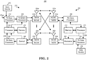
- FIG. 2 is a simplified block diagram of an embodiment of a transmitter system 210 (also known as the access network) and a receiver system 250 (also known as access terminal (AT) or user equipment (UE)) in a MIMO system 200.
- a transmitter system 210 also known as the access network
- a receiver system 250 also known as access terminal (AT) or user equipment (UE)
- traffic data for a number of data streams is provided from a data source 212 to a transmit (TX) data processor 214.
- TX transmit
- each data stream is transmitted over a respective transmit antenna.
- TX data processor 214 formats, codes, and interleaves the traffic data for each data stream based on a particular coding scheme selected for that data stream to provide coded data.
- the coded data for each data stream may be multiplexed with pilot data using OFDM techniques.
- the pilot data is typically a known data pattern that is processed in a known manner and may be used at the receiver system to estimate the channel response.
- the multiplexed pilot and coded data for each data stream is then modulated (i.e., symbol mapped) based on a particular modulation scheme (e.g., BPSK, QPSK, M-PSK, or M-QAM) selected for that data stream to provide modulation symbols.
- a particular modulation scheme e.g., BPSK, QPSK, M-PSK, or M-QAM
- the data rate, coding, and modulation for each data stream may be determined by instructions performed by processor 230.
- TX MIMO processor 220 may further process the modulation symbols (e.g., for OFDM).
- TX MIMO processor 220 then provides N T modulation symbol streams to N T transmitters (TMTR) 222a through 222t.
- TMTR TX MIMO processor 220 applies beamforming weights to the symbols of the data streams and to the antenna from which the symbol is being transmitted.
- Each transmitter 222 receives and processes a respective symbol stream to provide one or more analog signals, and further conditions (e.g., amplifies, filters, and upconverts) the analog signals to provide a modulated signal suitable for transmission over the MIMO channel.
- N T modulated signals from transmitters 222a through 222t are then transmitted from N T antennas 224a through 224t, respectively.
- the transmitted modulated signals are received by N R antennas 252a through 252r and the received signal from each antenna 252 is provided to a respective receiver (RCVR) 254a through 254r.
- Each receiver 254 conditions (e.g., filters, amplifies, and downconverts) a respective received signal, digitizes the conditioned signal to provide samples, and further processes the samples to provide a corresponding "received" symbol stream.
- An RX data processor 260 then receives and processes the N R received symbol streams from N R receivers 254 based on a particular receiver processing technique to provide N T "detected" symbol streams.
- the RX data processor 260 then demodulates, deinterleaves, and decodes each detected symbol stream to recover the traffic data for the data stream.
- the processing by RX data processor 260 is complementary to that performed by TX MIMO processor 220 and TX data processor 214 at transmitter system 210.
- a processor 270 periodically determines which pre-coding matrix to use (discussed below). Processor 270 formulates a reverse link message comprising a matrix index portion and a rank value portion.
- the reverse link message may comprise various types of information regarding the communication link and/or the received data stream.
- the reverse link message is then processed by a TX data processor 238, which also receives traffic data for a number of data streams from a data source 236, modulated by a modulator 280, conditioned by transmitters 254a through 254r, and transmitted back to transmitter system 210.
- the modulated signals from receiver system 250 are received by antennas 224, conditioned by receivers 222, demodulated by a demodulator 240, and processed by a RX data processor 242 to extract the reserve link message transmitted by the receiver system 250.
- Processor 230 determines which pre-coding matrix to use for determining the beamforming weights then processes the extracted message.
- FIG. 3 shows an alternative simplified functional block diagram of a communication device according to one embodiment of the invention.
- the communication device 300 in a wireless communication system can be utilized for realizing the UEs (or ATs) 116 and 122 in FIG. 1 or the base station (or AN) 100 in FIG. 1 , and the wireless communications system is preferably the NR system.
- the communication device 300 may include an input device 302, an output device 304, a control circuit 306, a central processing unit (CPU) 308, a memory 310, a program code 312, and a transceiver 314.
- the control circuit 306 executes the program code 312 in the memory 310 through the CPU 308, thereby controlling an operation of the communications device 300.
- the communications device 300 can receive signals input by a user through the input device 302, such as a keyboard or keypad, and can output images and sounds through the output device 304, such as a monitor or speakers.
- the transceiver 314 is used to receive and transmit wireless signals, delivering received signals to the control circuit 306, and outputting signals generated by the control circuit 306 wirelessly.
- the communication device 300 in a wireless communication system can also be utilized for realizing the AN 100 in FIG. 1 .
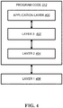
- FIG. 4 is a simplified block diagram of the program code 312 shown in FIG. 3 in accordance with one embodiment of the invention.
- the program code 312 includes an application layer 400, a Layer 3 portion 402, and a Layer 2 portion 404, and is coupled to a Layer 1 portion 406.
- the Layer 3 portion 402 generally performs radio resource control.
- the Layer 2 portion 404 generally performs link control.
- the Layer 1 portion 406 generally performs physical connections.
- New RAT New RAT
- time and frequency resource e.g. from ultra-low latency ( ⁇ 0.5 ms) to delay-tolerant traffic for MTC, from high peak rate for eMBB to very low data rate for MTC.
- ultra-low latency ⁇ 0.5 ms
- delay-tolerant traffic for MTC from high peak rate for eMBB to very low data rate for MTC.
- An important focus of this study is low latency aspect, e.g. short TTI, while other aspect of mixing or adapting different TTIs can also be considered in the study.
- forward compatibility is an important consideration in initial NR frame structure design as not all features of NR would be included in the beginning phase or release.
- Reducing latency of protocol is an important improvement between different generations or releases, which can improve efficiency as well as meeting new application requirements, e.g. real-time service.
- An effective method frequently adopted to reduce latency is to reduce the length of TTIs, from 10 ms in 3G to 1 ms in LTE.
- LTE numerology As an example, it comprises 14 OFDM symbol in 1 ms and a subcarrier spacing of 15 KHz.
- the subcarrier spacing goes to 30KHz, under the assumption of same FFT size and same CP structure, there would be 28 OFDM symbols in 1 ms, equivalently the TTI become 0.5 ms if the number of OFDM symbol in a TTI is kept the same. This implies the design between different TTI lengths can be kept common, with good scalability performed on the subcarrier spacing.
- subcarrier spacing selection e.g. FFT size, definition or number of PRB, the design of CP, supportable system bandwidth, etc.
- NR considers larger system bandwidth, and larger coherence bandwidth, inclusion of a larger sub carrier spacing is a nature choice.
- RAN1 works as band agnostic manner, i.e. a scheme or feature would be assumed to be applicable for all frequency bands and in the following RAN4 would derive relevant test case considering if some combination is unrealistic or deployment can be done reasonably. This rule would still be assumed in NR, while some companies do see there would be restriction for sure as the frequency range of NR is quite high:
- 3GPP TS 38.211 provides the following additional details of NR frame structure, channel and numerology design:
- Each frame is divided into two equally-sized half-frames of five subframes each with half-frame 0 consisting of subframes 0-4 and half-frame 1 consisting of subframes 5-9.
- slots are numbered n s ⁇ ⁇ 0 , ... , N slot subframe , ⁇ ⁇ 1 in increasing order within a subframe and n s , f ⁇ ⁇ 0 , ... , N slot frame , ⁇ ⁇ 1 in increasing order within a frame.
- N symb slot consecutive OFDM symbols in a slot where N symb slot depends on the cyclic prefix as given by Tables 4.3.2-1 and 4.3.2-2.
- the start of slot n s ⁇ in a subframe is aligned in time with the start of OFDM symbol n s ⁇ N symb slot in the same subframe.
- OFDM symbols in a slot can be classified as 'downlink', 'flexible', or 'uplink'. Signaling of slot formats is described in subclause 11.1 of [5, TS 38.213].
- the UE shall assume that downlink transmissions only occur in 'downlink' or 'flexible' symbols.
- the UE In a slot in an uplink frame, the UE shall only transmit in 'uplink' or 'flexible' symbols.
- a UE not capable of full-duplex communication and not supporting simultaneous transmission and reception as defined by parameter simultaneousRxTxInterBandENDC, simultaneousRxTxlnterBandCA or simultaneousRxTxSUL [10, TS 38.306] among all cells within a group of cells is not expected to transmit in the uplink in one cell within the group of cells earlier than N Rx - T x T c after the end of the last received downlink symbol in the same or different cell within the group of cells where N Rx-Tx is given by Table 4.3.2-3.
- a UE not capable of full-duplex communication and not supporting simultaneous transmission and reception as defined by parameter simultaneousRxTxInterBandENDC, simultaneousRxTxInterBandCA or simultaneousRxTxSUL [10, TS 38.306] among all cells within a group of cells is not expected to receive in the downlink in one cell within the group of cells earlier than N Tx-Rx T c after the end of the last transmitted uplink symbol in the same or different cell within the group of cells where N Tx-Rx is given by Table 4.3.2-3.
- a UE not capable of full-duplex communication is not expected to transmit in the uplink earlier than N Rx-Tx T c after the end of the last received downlink symbol in the same cell where N Rx-Tx is given by Table 4.3.2-3.
- a UE not capable of full-duplex communication is not expected to receive in the downlink earlier than N Tx-Rx T c after the end of the last transmitted uplink symbol in the same cell where N Tx-Rx is given by Table 4.3.2-3.
- An antenna port is defined such that the channel over which a symbol on the antenna port is conveyed can be inferred from the channel over which another symbol on the same antenna port is conveyed.
- the channel over which a PDSCH symbol on one antenna port is conveyed can be inferred from the channel over which a DM-RS symbol on the same antenna port is conveyed only if the two symbols are within the same resource as the scheduled PDSCH, in the same slot, and in the same PRG as described in clause 5.1.2.3 of [6, TS 38.214].
- the channel over which a PDCCH symbol on one antenna port is conveyed can be inferred from the channel over which a DM-RS symbol on the same antenna port is conveyed only if the two symbols are within resources for which the UE may assume the same precoding being used as described in clause 7.3.2.2.
- the channel over which a PBCH symbol on one antenna port is conveyed can be inferred from the channel over which a DM-RS symbol on the same antenna port is conveyed only if the two symbols are within a SS/PBCH block transmitted within the same slot, and with the same block index according to clause 7.4.3.1.
- Two antenna ports are said to be quasi co-located if the large-scale properties of the channel over which a symbol on one antenna port is conveyed can be inferred from the channel over which a symbol on the other antenna port is conveyed.
- the large-scale properties include one or more of delay spread, Doppler spread, Doppler shift, average gain, average delay, and spatial Rx parameters.
- a resource grid of N grid , x size , ⁇ N sc RB subcarriers and N symb subframe , ⁇ OFDM symbols is defined, starting at common resource block N grid start , ⁇ indicated by higher-layer signalling.
- the carrier bandwidth N grid size , ⁇ for subcarrier spacing configuration ⁇ is given by the higher-layer parameter carrierBandwidth in the SCS-SpecificCarrier IE.
- the starting position N grid start , ⁇ for subcarrier spacing configuration ⁇ is given by the higher-layer parameter offsetToCarrier in the SCS-SpecificCarrier IE.
- the frequency location of a subcarrier refers to the center frequency of that subcarrier.
- the higher-layer parameter txDirectCurrentLocation in the SCS-SpecificCarrier IE indicates the location of the transmitter DC subcarrier in the downlink for each of the numerologies configured in the downlink. Values in the range 0 - 3299 represent the number of the DC subcarrier and the value 3300 indicates that the DC subcarrier is located outside the resource grid.
- the higher-layer parameter txDirectCurrentLocation in the UplinkTxDirectCurrentBWP IE indicates the location of the transmitter DC subcarrier in the uplink for each of the configured bandwidth parts, including whether the DC subcarrier location is offset by 7.5 kHz relative to the center of the indicated subcarrier or not.
- Values in the range 0 - 3299 represent the number of the DC subcarrier
- the value 3300 indicates that the DC subcarrier is located outside the resource grid
- the value 3301 indicates that the position of the DC subcarrier in the uplink is undetermined.
- Each element in the resource grid for antenna port p and subcarrier spacing configuration ⁇ is called a resource element and is uniquely identified by ( k , l ) p, ⁇ where k is the index in the frequency domain and l refers to the symbol position in the time domain relative to some reference point.
- Resource element ( k, l ) p, ⁇ corresponds to a physical resource and the complex value a k , l p ⁇ .
- the indices p and ⁇ may be dropped, resulting in a k , l p or a k,l .
- Point A serves as a common reference point for resource block grids and is obtained from:
- Common resource blocks are numbered from 0 and upwards in the frequency domain for subcarrier spacing configuration ⁇ .
- the center of subcarrier 0 of common resource block 0 for subcarrier spacing configuration ⁇ coincides with 'point A'.
- n CRB ⁇ ⁇ k N sc RB ⁇
- Physical resource blocks for subcarrier configuration ⁇ are defined within a bandwidth part and numbered from 0 to N BWP , i size , ⁇ ⁇ 1 where i is the number of the bandwidth part.
- the index ⁇ may be dropped.
- Virtual resource blocks are defined within a bandwidth part and numbered from 0 to N BWP , i size ⁇ 1 where i is the number of the bandwidth part.
- a bandwidth part is a subset of contiguous common resource blocks defined in subclause 4.4.4.3 for a given numerology ⁇ i in bandwidth part i on a given carrier.
- the starting position N BWP , i start , ⁇ and the number of resource blocks N BWP , i size , ⁇ in a bandwidth part shall fulfil N grid , x start , ⁇ ⁇ N BWP , i start , ⁇ ⁇ N grid , x start , ⁇ + N grid , x size , ⁇ and N grid , x start , ⁇ ⁇ N BWP , i start , ⁇ + N BWP , i size , ⁇ ⁇ N grid , x start , ⁇ + N grid , x size , ⁇ , respectively.
- Configuration of a bandwidth part is described in clause 12 of [5, TS 38.213].
- a UE can be configured with up to four bandwidth parts in the downlink with a single downlink bandwidth part being active at a given time.
- the UE is not expected to receive PDSCH, PDCCH, or CSI-RS (except for RRM) outside an active bandwidth part.
- a UE can be configured with up to four bandwidth parts in the uplink with a single uplink bandwidth part being active at a given time. If a UE is configured with a supplementary uplink, the UE can in addition be configured with up to four bandwidth parts in the supplementary uplink with a single supplementary uplink bandwidth part being active at a given time.
- the UE shall not transmit PUSCH or PUCCH outside an active bandwidth part. For an active cell, the UE shall not transmit SRS outside an active bandwidth part.
- the index ⁇ may be dropped from N BWP , i start , ⁇ , N BWP , i size , ⁇ , N grid , x start , ⁇ , and N grid , x size , ⁇ .
- Transmissions in multiple cells can be aggregated. Unless otherwise noted, the description in this specification applies to each of the serving cells.
- TA UL timing advance
- TA is a timing difference between UL transmission timing and DL reception timing at UE side.
- TA is a time duration UL timing ahead of DL timing.
- TA could accommodate a round trip time (RTT) between a bases station and a UE. Since UEs served by a bases station would have different RTTs, if all UE transmit it UL as the same timing as receiving its DL, the UL signals from different UEs would cause interference to each other, as they would not arrive at the same time (or around the same time).
- RTT round trip time
- TA is introduced to allow UL signals (e.g.
- a UE closer to a base station it would be likely to have a shorter TA.
- a UE farther from a base station it would be likely to have a longer TA.
- An initial value of TA is obtained before UE perform regular UL transmission.
- the initial TA value is estimated by a random access procedure.
- a UE would firstly synchronize its DL timing to a DL signal, e.g. SSB from a base station.
- a UE transmits a preamble to a base station.
- the preamble is transmitted with TA value equal to 0 or a small offset value relative to the DL timing.
- Design of the preamble sequence allows a base station to estimate TA value of a UE (e.g. amount of time UE needs to advance its transmission timing comparing with transmitting a preamble) when receiving preamble from the UE.
- the base station would then transmit a response, random access response, comprising a TA value (for that preamble and/or that PRACH resource).
- the UE could use the TA value to adjust its following UL transmission timing (e.g. a Msg3 transmission). Whether the TA could be continuously used in the following UL transmission may subject to other condition(s), e.g. whether the random access procedure is successfully complete or not.
- This TA value would be maintained or updated from time to time, e.g. when UL transmission is to be performed.
- the UE may change its location due to mobility, or the path between a base station and the UE changes, resulting in desired TA value change.
- the base station could send a TA adjustment value to update UE's TA value.
- the base station could send an order to request UE to perform a random access procedure.
- the UE could acquire new TA during the random access procedure.
- a TA validity timer is maintained by a UE (as well as by a base station) to judge whether a UE has a valid TA or not. If UE does not have valid TA, it is not allowed to transmit most of the UL signal. For example, if UE does not have valid TA, it is not allowed to transmit PUCCH and/or PUSCH and/or SRS. If UE does not have valid TA, it is allowed to transmit PRACH. More details of procedures related to timing advance are provided below from 3GPP TS 38.213, TS 38.211, and TS 38.321.
- Cell search is the procedure for a UE to acquire time and frequency synchronization with a cell and to detect the physical layer Cell ID of the cell.
- a UE receives the following synchronization signals (SS) in order to perform cell search: the primary synchronization signal (PSS) and secondary synchronization signal (SSS) as defined in [4, TS 38.211].
- PSS primary synchronization signal
- SSS secondary synchronization signal
- a UE assumes that reception occasions of a physical broadcast channel (PBCH), PSS, and SSS are in consecutive symbols, as defined in [4, TS 38.211], and form a SS/PBCH block.
- PBCH physical broadcast channel
- PSS PSS
- SSS SSS
- PBCH DM-RS PBCH DM-RS
- PBCH data have same EPRE.
- the UE may assume that the ratio of PSS EPRE to SSS EPRE in a SS/PBCH block is either 0 dB or 3 dB.
- the UE may assume that the ratio of PDCCH DMRS EPRE to SSS EPRE is within -8 dB and 8 dB when the UE monitors PDCCHs for a DCI format 1_0 with CRC scrambled by SI-RNTI, P-RNTI, or RA-RNTI.
- the first symbol indexes for candidate SS/PBCH blocks are determined according to the SCS of SS/PBCH blocks as follows, where index 0 corresponds to the first symbol of the first slot in a half-frame.
- the applicable cases for a cell depend on a respective frequency band, as provided in [8-1, TS 38.101-1] and [8-2, TS 38.101-2]. A same case applies for all SS/PBCH blocks on the cell.
- Case B applies for frequency bands with only 15 kHz SS/PBCH block SCS as specified in [8-1, TS 38.101-1], and the case specified for 30 kHz SS/PBCH block SCS in [8-1, TS 38.101-1] applies for frequency bands with 30 kHz SS/PBCH block SCS or both 15 kHz and 30 kHz SS/PBCH block SCS as specified in [8-1, TS 38.101-1].
- a UE configured to operate with carrier aggregation over a set of cells in a frequency band of FR2 or with frequency-contiguous carrier aggregation over a set of cells in a frequency band of FR1
- the UE if the UE is provided SCS values by ssbSubcarrierSpacing for receptions of SS/PBCH blocks on any cells from the set of cells, the UE expects the SCS values to be same.
- the candidate SS/PBCH blocks in a half frame are indexed in an ascending order in time from 0 to L max -1.
- a UE can be provided per serving cell by ssb-periodicityServingCell a periodicity of the half frames for reception of the SS/PBCH blocks for the serving cell. If the UE is not configured a periodicity of the half frames for receptions of the SS/PBCH blocks, the UE assumes a periodicity of a half frame. A UE assumes that the periodicity is same for all SS/PBCH blocks in the serving cell.
- a UE may assume that half frames with SS/PBCH blocks occur with a periodicity of 2 frames.
- the UE Upon detection of a SS/PBCH block, the UE determines from MIB that a CORESET for Type0-PDCCH CSS set, as described in Subclause 13, is present if k SSB ⁇ 23 [4, TS 38.211] for FR1 or if k SSB ⁇ 11 for FR2.
- the UE determines from MIB that a CORESET for Type0-PDCCH CSS set is not present if k SSB > 23 for FR1 or if k SSB >11 for FR2; the CORESET for Type0-PDCCH CSS set may be provided by PDCCH-ConfigCommon.
- a UE For a serving cell without transmission of SS/PBCH blocks, a UE acquires time and frequency synchronization with the serving cell based on receptions of SS/PBCH blocks on the PCell, or on the PSCell, of the cell group for the serving cell.
- a UE can be provided a value N TA,offset of a timing advance offset for a serving cell by n-TimingAdvanceOffset for the serving cell. If the UE is not provided n-TimingAdvanceOffset for a serving cell, the UE determines a default value N TA,offset of the timing advance offset for the serving cell as described in [10, TS 38.133].
- a same timing advance offset value N TA,offset applies to both carriers.
- the UE Upon reception of a timing advance command for a TAG, the UE adjusts uplink timing for PUSCH/SRS/PUCCH transmission on all the serving cells in the TAG based on a value N TA,offset that the UE expects to be same for all the serving cells in the TAG and based on the received timing advance command where the uplink timing for PUSCH/SRS/PUCCH transmissions is the same for all the serving cells in the TAG.
- the UE For a band with synchronous contiguous intra-band EN-DC in a band combination with non-applicable maximum transmit timing difference requirements as described in Note 1 of Table 7.5.3-1 of [10, TS 38.133], if the UE indicates ul-TimingAlignmentEUTRA-NR as 'required' and uplink transmission timing based on timing adjustment indication for a TAG from MCG and a TAG from SCG are determined to be different by the UE, the UE adjusts the transmission timing for PUSCH/SRS/PUCCH transmission on all serving cells part of the band with the synchronous contiguous intra-band EN-DC based on timing adjustment indication for a TAG from a serving cell in MCG in the band.
- the UE is not expected to transmit a PUSCH/SRS/PUCCH in one CG when the PUSCH/SRS/PUCCH is overlapping in time, even partially, with random access preamble transmitted in another CG.
- the timing advance command for a TAG indicates the change of the uplink timing relative to the current uplink timing for the TAG in multiples of 16 ⁇ 64 ⁇ T c /2 ⁇ .
- the start timing of the random access preamble is described in [4, TS 38.211].
- N TA is defined in [4, TS 38.211] and is relative to the SCS of the first uplink transmission from the UE after the reception of the random access response.
- the timing advance command value is relative to the largest SCS of the multiple active UL BWPs.
- the applicable N TA_new value for an UL BWP with lower SCS may be rounded to align with the timing advance granularity for the UL BWP with the lower SCS while satisfying the timing advance accuracy requirements in [10, TS38.133].
- Adjustment of an N TA value by a positive or a negative amount indicates advancing or delaying the uplink transmission timing for the TAG by a corresponding amount, respectively.
- N T , 1 is a time duration in msec of N 1 symbols corresponding to a PDSCH processing time for UE processing capability 1 when additional PDSCH DM-RS is configured
- N T,2 is a time duration in msec of N 2 symbols corresponding to a PUSCH preparation time for UE processing capability 1 [6, TS 38.214]
- N TA,max is the maximum timing advance value in msec that can be provided by a TA command field of 12 bits
- N slot subframe , ⁇ is the number of slots per subframe
- T sf is the
- N 1 and N 2 are determined with respect to the minimum SCS among the SCSs of all configured UL BWPs for all uplink carriers in the TAG and of all configured DL BWPs for the corresponding downlink carriers.
- Slot n and N slot subframe , ⁇ are determined with respect to the minimum SCS among the SCSs of all configured UL BWPs for all uplink carriers in the TAG.
- N TA,max is determined with respect to the minimum SCS among the SCSs of all configured UL BWPs for all uplink carriers in the TAG and for all configured initial UL BWPs provided by initialUplinkBWP.
- a UE changes an active UL BWP between a time of a timing advance command reception and a time of applying a corresponding adjustment for the uplink transmission timing
- the UE determines the timing advance command value based on the SCS of the new active UL BWP. If the UE changes an active UL BWP after applying an adjustment for the uplink transmission timing, the UE assumes a same absolute timing advance command value before and after the active UL BWP change.
- the UE changes N TA accordingly.
- Layer 1 Prior to initiation of the physical random access procedure, Layer 1 receives from higher layers a set of SS/PBCH block indexes and provides to higher layers a corresponding set of RSRP measurements.
- Layer 1 Prior to initiation of the physical random access procedure, Layer 1 receives the following information from the higher layers:
- the L1 random access procedure includes the transmission of random access preamble (Msg1) in a PRACH, random access response (RAR) message with a PDCCH/PDSCH (Msg2), and when applicable, the transmission of a PUSCH scheduled by a RAR UL grant, and PDSCH for contention resolution.
- Msg1 random access preamble
- RAR random access response
- Msg2 PDCCH/PDSCH
- a PRACH transmission is with a same SCS as a PRACH transmission initiated by higher layers.
- a UE is configured with two UL carriers for a serving cell and the UE detects a PDCCH order, the UE uses the UL/SUL indicator field value from the detected PDCCH order to determine the UL carrier for the corresponding PRACH transmission.
- Physical random access procedure is triggered upon request of a PRACH transmission by higher layers or by a PDCCH order.
- a configuration by higher layers for a PRACH transmission includes the following:
- a PRACH is transmitted using the selected PRACH format with transmission power P PRACH, b,f,c (i), as described in Subclause 7.4, on the indicated PRACH resource.
- a UE is provided a number N of SS/PBCH blocks associated with one PRACH occasion and a number R of contention based preambles per SS/PBCH block per valid PRACH occasion by ssb-perRACH-OccasionAndCB-PreamblesPerSSB. If N ⁇ 1 , one SS/PBCH block is mapped to 1/ N consecutive valid PRACH occasions and R contention based preambles with consecutive indexes associated with the SS/PBCH block per valid PRACH occasion start from preamble index 0.
- N 1
- R contention based preambles with consecutive indexes associated with SS/PBCH block n 0 ⁇ n ⁇ N -1, per valid PRACH occasion start from preamble index n ⁇ N preamble total / N where N preamble total is provided by totalNumberOfRA-Preambles and is an integer multiple of N .
- a UE For link recovery, a UE is provided N SS/PBCH blocks associated with one PRACH occasion by ssb-perRACH-Occasion in BeamFailureRecoveryConfig.
- N SS/PBCH blocks For a dedicated RACH configuration provided by RACH-ConfigDedicated, if cfra is provided, a UE is provided N SS/PBCH blocks associated with one PRACH occasion by ssb-perRACH-Occasion in occasions. If N ⁇ 1, one SS/PBCH block is mapped to 1/ N consecutive valid PRACH occasions. If N ⁇ 1, all consecutive N SS/PBCH blocks are associated with one PRACH occasion.
- SS/PBCH block indexes provided by ssb-PositionsInBurst in SIB1 or in ServingCellConfigCommon are mapped to valid PRACH occasions in the following order where the parameters are described in [4, TS 38.211].
- An association period, starting from frame 0, for mapping SS/PBCH blocks to PRACH occasions is the smallest value in the set determined by the PRACH configuration period according Table 8.1-1 such that N Tx SSB SS/PBCH blocks are mapped at least once to the PRACH occasions within the association period, where a UE obtains N Tx SSB from the value of ssb-PositionsInBurst in SIB1 or in ServingCellConfigCommon. If after an integer number of SS/PBCH blocks to PRACH occasions mapping cycles within the association period there is a set of PRACH occasions that are not mapped to N Tx SSB SS/PBCH blocks, no SS/PBCH blocks are mapped to the set of PRACH occasions.
- An association pattern period includes one or more association periods and is determined so that a pattern between PRACH occasions and SS/PBCH blocks repeats at most every 160 msec. PRACH occasions not associated with SS/PBCH blocks after an integer number of association periods, if any, are not used for PRACH transmissions.
- the PRACH mask index is indicated by ra-ssb-OccasionMaskIndex which indicates the PRACH occasions for the PRACH transmission where the PRACH occasions are associated with the selected SS/PBCH block index.
- the PRACH occasions are mapped consecutively per corresponding SS/PBCH block index.
- the indexing of the PRACH occasion indicated by the mask index value is reset per mapping cycle of consecutive PRACH occasions per SS/PBCH block index.
- the UE selects for a PRACH transmission the PRACH occasion indicated by PRACH mask index value for the indicated SS/PBCH block index in the first available mapping cycle.
- the ordering of the PRACH occasions is
- a value of ra-OccasionList [12, TS 38.331], if csirs-ResourceList is provided, indicates a list of PRACH occasions for the PRACH transmission where the PRACH occasions are associated with the selected CSI-RS index indicated by csi-RS.
- the indexing of the PRACH occasions indicated by ra-OccasionList is reset per association pattern period.
- a PRACH occasion in a PRACH slot is valid if it does not precede a SS/PBCH block in the PRACH slot and starts at least N gap symbols after a last SS/PBCH block reception symbol, where N gap is provided in Table 8.1-2.
- a PRACH occasion in a PRACH slot is valid if
- N gap 0.
- a UE For single cell operation or for operation with carrier aggregation in a same frequency band, a UE does not transmit PRACH and PUSCH/PUCCH/SRS in a same slot or when a gap between the first or last symbol of a PRACH transmission in a first slot is separated by less than N symbols from the last or first symbol, respectively, of a PUSCH/PUCCH/SRS transmission in a second slot
- a UE In response to a PRACH transmission, a UE attempts to detect a DCI format 1_0 with CRC scrambled by a corresponding RA-RNTI during a window controlled by higher layers [11, TS 38.321].
- the window starts at the first symbol of the earliest CORESET the UE is configured to receive PDCCH for Type1-PDCCH CSS set, as defined in Subclause 10.1, that is at least one symbol, after the last symbol of the PRACH occasion corresponding to the PRACH transmission, where the symbol duration corresponds to the SCS for Type1-PDCCH CSS set as defined in Subclause 10.1.
- the length of the window in number of slots, based on the SCS for Type1-PDCCH CSS set, is provided by ra-ResponseWindow.
- the UE If the UE detects the DCI format 1_0 with CRC scrambled by the corresponding RA-RNTI and a transport block in a corresponding PDSCH within the window, the UE passes the transport block to higher layers.
- the higher layers parse the transport block for a random access preamble identity (RAPID) associated with the PRACH transmission. If the higher layers identify the RAPID in RAR message(s) of the transport block, the higher layers indicate an uplink grant to the physical layer. This is referred to as random access response (RAR) UL grant in the physical layer.
- RAPID random access preamble identity
- the UE may assume same DM-RS antenna port quasi co-location properties, as described in [6, TS 38.214], as for a SS/PBCH block or a CSI-RS resource the UE used for PRACH association, as described in Subclause 8.1, regardless of whether or not the UE is provided TCI-State for the CORESET where the UE receives the PDCCH with the DCI format 1_0.
- the UE may assume that the PDCCH that includes the DCI format 1_0 and the PDCCH order have same DM-RS antenna port quasi co-location properties.
- the UE may assume the DM-RS antenna port quasi co-location properties of the CORESET associated with the Type1-PDCCH CSS set for receiving the PDCCH that includes the DCI format 1_0.
- a RAR UL grant schedules a PUSCH transmission from the UE.
- the contents of the RAR UL grant, starting with the MSB and ending with the LSB, are given in Table 8.2-1.
- the UE transmits the PUSCH without frequency hopping; otherwise, the UE transmits the PUSCH with frequency hopping.
- the UE determines the MCS of the PUSCH transmission from the first sixteen indexes of the applicable MCS index table for PUSCH as described in [6, TS 38.214].
- the TPC command value ⁇ msg 2, b,f,c is used for setting the power of the PUSCH transmission, as described in Subclause 7.1.1, and is interpreted according to Table 8.2-2.
- the CSI request field is reserved.
- the UE receives subsequent PDSCH using same SCS as for the PDSCH reception providing the RAR message.
- the UE procedure is as described in [11, TS 38.321].
- An active UL BWP as described in Subclause 12 and in [4, TS 38.211], for a PUSCH transmission scheduled by a RAR UL grant is indicated by higher layers. For determining the frequency domain resource allocation for the PUSCH transmission within the active UL BWP
- the frequency domain resource allocation is by uplink resource allocation type 1 [6, TS 38.214].
- a UE processes the frequency domain resource assignment field as follows
- a UE determines whether or not to apply transform precoding as described in [6, TS 38.214].
- the frequency offset for the second hop is given in Table 8.3-1.
- a SCS for the PUSCH transmission is provided by subcarrierSpacing in BWP-UplinkCommon.
- a UE transmits PRACH and the PUSCH on a same uplink carrier of a same serving cell.
- a UE transmits a transport block in a PUSCH scheduled by a RAR UL grant in a corresponding RAR message using redundancy version number 0. If a TC-RNTI is provided by higher layers, the scrambling initialization of the PUSCH corresponding to the RAR UL grant in clause 8.2 is by TC-RNTI. Otherwise, the scrambling initialization of the PUSCH corresponding to the RAR UL grant in clause 8.2 is by C-RNTI. Msg3 PUSCH retransmissions, if any, of the transport block, are scheduled by a DCI format 0_0 with CRC scrambled by a TC-RNTI provided in the corresponding RAR message [11, TS 38.321]. The UE always transmits the PUSCH scheduled by a RAR UL grant without repetitions .
- a UE With reference to slots for a PUSCH transmission scheduled by a RAR UL grant, if a UE receives a PDSCH with a RAR message ending in slot n for a corresponding PRACH transmission from the UE, the UE transmits the PUSCH in slot n + k 2 + ⁇ , where k 2 and ⁇ are provided in [6, TS 38.214].
- the UE In response to a PUSCH transmission scheduled by a RAR UL grant when a UE has not been provided a C-RNTI, the UE attempts to detect a DCI format 1_0 with CRC scrambled by a corresponding TC-RNTI scheduling a PDSCH that includes a UE contention resolution identity [11, TS 38.321]. In response to the PDSCH reception with the UE contention resolution identity, the UE transmits HARQ-ACK information in a PUCCH. The PUCCH transmission is within a same active UL BWP as the PUSCH transmission.
- a minimum time between the last symbol of the PDSCH reception and the first symbol of the corresponding PUCCH transmission with the HARQ-ACK information is equal to N T,1 + 0.5 msec.
- the UE may assume the PDCCH carrying the DCI format has the same DM-RS antenna port quasi co-location properties, as described in [6, TS 38.214], as for a SS/PBCH block the UE used for PRACH association, as described in Subclause 8.1, regardless of whether or not the UE is provided TCI-State for the CORESET where the UE receives the PDCCH with the DCI format.
- Each frame is divided into two equally-sized half-frames of five subframes each with half-frame 0 consisting of subframes 0-4 and half-frame 1 consisting of subframes 5-9. There is one set of frames in the uplink and one set of frames in the downlink on a carrier.
- the Random Access procedure described in this clause is initiated by a PDCCH order, by the MAC entity itself, or by RRC for the events in accordance with TS 38.300 [2]. There is only one Random Access procedure ongoing at any point in time in a MAC entity.
- the Random Access procedure on an SCell shall only be initiated by a PDCCH order with ra-PreambleIndex different from 0b000000.
- NOTE 1 If a new Random Access procedure is triggered while another is already ongoing in the MAC entity, it is up to UE implementation whether to continue with the ongoing procedure or start with the new procedure (e.g. for SI request).
- RRC configures the following parameters for the Random Access procedure:
- Preambles group B is included for each SSB.
- the MAC entity shall:
- the MAC entity shall: NOTE: When the UE determines if there is an SSB with SS-RSRP above rsrp-ThresholdSSB or a CSI-RS with CSI-RSRP above rsrp-ThresholdCSI-RS, the UE uses the latest unfiltered L1-RSRP measurement.
- the MAC entity shall, for each Random Access Preamble:
- s_id is the index of the first OFDM symbol of the PRACH occasion (0 ⁇ s_id ⁇ 14)
- t_id is the index of the first slot of the PRACH occasion in a system frame (0 ⁇ t_id ⁇ 80)
- the subcarrier spacing to determine t_id is based on the value of ⁇ specified in clause 5.3.2 in TS 38.211 [8]
- f_id is the index of the PRACH occasion in the frequency domain (0 ⁇ f_id ⁇ 8)
- ul_carrier_id is the UL carrier used for Random Access Preamble transmission (0 for NUL carrier, and 1 for SUL carrier).
- the MAC entity shall: NOTE: If within a Random Access procedure, an uplink grant provided in the Random Access Response for the same group of contention-based Random Access Preambles has a different size than the first uplink grant allocated during that Random Access procedure, the UE behavior is not defined.
- the MAC entity may stop ra-ResponseWindow (and hence monitoring for Random Access Response(s)) after successful reception of a Random Access Response containing Random Access Preamble identifiers that matches the transmitted PREAMBLE_INDEX.
- HARQ operation is not applicable to the Random Access Response reception.
- the MAC entity shall:
- the MAC entity Upon completion of the Random Access procedure, the MAC entity shall:
- RRC configures the following parameters for the maintenance of UL time alignment:
- the MAC entity shall:
- the MAC entity When the MAC entity stops uplink transmissions for an SCell due to the fact that the maximum uplink transmission timing difference between TAGs of the MAC entity or the maximum uplink transmission timing difference between TAGs of any MAC entity of the UE is exceeded, the MAC entity considers the timeAlignmentTimer associated with the SCell as expired.
- the MAC entity shall not perform any uplink transmission on a Serving Cell except the Random Access Preamble transmission when the timeAlignmentTimer associated with the TAG to which this Serving Cell belongs is not running. Furthermore, when the timeAlignmentTimer associated with the PTAG is not running, the MAC entity shall not perform any uplink transmission on any Serving Cell except the Random Access Preamble transmission on the SpCell.
- a MAC PDU consists of one or more MAC subPDUs and optionally padding.
- Each MAC subPDU consists one of the following:
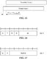
- a MAC subheader with Backoff Indicator consists of five header fields E/T/R/R/BI as described in Figure 6.1.5-1.
- a MAC subPDU with Backoff Indicator only is placed at the beginning of the MAC PDU, if included.
- 'MAC subPDU(s) with RAPID only' and 'MAC subPDU(s) with RAPID and MAC RAR' can be placed anywhere between MAC subPDU with Backoff Indicator only (if any) and padding (if any).
- a MAC subheader with RAPID consists of three header fields E/T/RAPID as described in Figure 6.1.5-2.
- Padding is placed at the end of the MAC PDU if present. Presence and length of padding is implicit based on TB size, size of MAC subPDU(s).
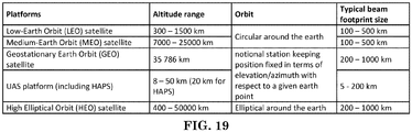
- Satellite communication also known as non-terrestrial network (NTN)
- NTN non-terrestrial network
- High altitude platform station (HAPS) such as drone, unmanned aircraft, or balloon, could be considered as a category or type of NTN, e.g. with a smaller distance from earth.
- HAPS high altitude platform station
- the altitude, shape of orbit, mobility with respect to an earth point could be different.
- the altitude is quite high which would result in higher pathloss as well as higher propagation delay or round trip delay.
- GEO could enjoy the benefit of stationary with respect to an earth point, and could provide coverage for most places around the earth.
- LEO the altitude is relative short and thus the loss and delay are less comparing with GEO. LEO would move around the earth, with respect to an earth point, so that it could cover some area which would be difficult to cover by GEO, such as polar area.
- the speed of movement is very high so that such mobility creates another issue, e.g.
- Satellites covering a certain area would change from time to time with high speed. It is different from convention base station with fixed or almost fixed location. High roundtrip delay and higher base station mobility are major different factors comparing with convention mobile network. The issues induced by the factor need to be solved to make mobile service support via NTN possible.
- Uplink (UL) transmission timing is acquired based on relative timing.
- UL transmission timing is derived based on (or relative to) a Downlink (DL) reception timing.
- DL Downlink
- one-way propagation delay or the RTT could be quite large, e.g. up to hundreds of ms, since a distance between base station (e.g. satellite) could be quite large (e.g. 300 ⁇ 36,000km). Therefore, the latency of obtaining Timing Advance (TA) could be larger than conventional system.
- TA Timing Advance
- one or two round trip(s) is required to obtain an initial TA value or to update TA value, e.g. via random access procedure or a TA command Medium Access Control (MAC) Control Element (CE).
- MAC Medium Access Control
- CE Medium Access Control Element
- Synchronization Signal Block (SSB) periodicity is selected by a base station. The value could be up to 160ms. A 160ms SSB periodicity corresponds to an average of ⁇ 80 ms DL synchronization acquisition delay (e.g. for the case UE has not obtained DL synchronization).
- a relative timing based UL timing determination would induce delay comprising UL TA obtaining delay and/or DL sync delay.
- a first general concept of this invention is that a UE determines UL transmission timing of an UL signal based on absolute time.
- the absolute time is based on a clock of the UE.
- the absolute time may not be derived from a DL reception timing.
- the absolute time may comprise hour, minute, second, millisecond, microsecond, and/or nanosecond.
- the UE could determine a timing UL transmission begins or starts based on absolute time.
- the UE could also determine an UL subframe begins or starts based on absolute time.
- the UE could determine an UL slot begins or starts based on absolute time.
- An UL transmission could begin or start at the absolute time.
- An UL slot could begin or start at the absolute time.
- An UL subframe could begin or start at the absolute time.
- the UE could determine a timing advance based on absolute time.
- the absolute time could be an UL reception time of the signal at the base station.
- the absolute time could be derived based on an UL reception time of the signal at the base station, or based on an UL reception time at the base station a propagation delay between the UE and a base station.
- the absolute timing could be a beginning or start of UL subframe at the base station.
- the absolute time could be derived based on a beginning or start of UL subframe at the base station, or based on a beginning or start of UL subframe at the base station and a propagation delay between the UE and a base station.
- the absolute time could be a beginning or start of UL slot at the base station.
- the absolute time could be derived based on a beginning or start of UL slot at the base station, based on a beginning or start of UL slot at the base station and a propagation delay between the UE and a base station, or based on a propagation delay between the UE and a base station.
- the absolute time could be X-Y (e.g. 14:53:18.565000).
- a beginning of UL subframe or UL slot at the UE side could be set to X-Y.
- a UE could determine a beginning of UL subframe or UL slot based on an absolute time and a propagation delay between the UE and a base station.
- a beginning of UL reception time of a UL signal at base station is X (absolute time, e.g. 14:53:21.235000) and a propagation delay between the UE and a base station is Y (e.g. 2.67 ms)
- the absolute time could be X-Y (e.g. 14:53:18.565000).
- a beginning of UL transmission time of the UL signal at the UE side could be set to X-Y.
- a UE could determine UL transmission timing of an UL signal based on an absolute time and a propagation delay between the UE and a base station.
- the absolute timing could be fixed in the standard.
- the absolute time could be derived based on indication from a base station (or from another base station).
- the absolute time could be beginning or start of a DL subframe or a DL slot at the base station.
- the absolute time could be derived based on beginning or start of a DL subframe or a DL slot at the base station.
- the absolute time could be derived based on a timing difference between UL timing and DL timing at the base station.
- the absolute time could be derived based on a timing difference between (a boundary of) UL subframe and (a boundary of) DL subframe at the base station.
- the absolute timing could be stored by the UE.
- the absolute time could be derived from a procedure(s), e.g. a DL synchronization procedure and/or a random access procedure, during a previous attempt to access a cell.
- the absolute time is 14:53:21.235000, where 14 corresponds to hour. 53 corresponds to minute, and 21.235000 corresponds to second.
- An UL transmission or an UL subframe or an UL slot starts or begins at 14:53:21.235000.
- the absolute time is 0.235000 sec.
- An UL transmission or an UL subframe or an UL slot starts or begins at 14:53:21.235000, 14:53:22.235000 and so on.
- the absolute time is 0.235000 sec.
- An UL transmission or an UL subframe or an UL slot starts or begins at 14:53:21.235000, 14:53:22.235000, ....
- the absolute time is X.XXX000 sec., where each X represents a decimal digit corresponding to an integer between 0 and 9.
- An UL transmission or an UL subframe or an UL slot starts or begins at 14:53:21.235000, 14:53:22.236000, 14:53:22.237000, .
- the absolute time is 000 nanosecond.
- An UL transmission or an UL subframe or an UL slot starts or begins at 14:53:21.235000, 14:53:22.236000, 14:53:22.237000, ....
- the method could be used under some cases (e.g. (up-to-date) GPS information (such as location and/or satellite ephemeris) is available and/or UE's clock is precise and/or the absolute time could be derived and/or the UE is in connected mode and/or the UE has performed random access procedure (in the cell)).
- Conventional method to obtain UL transmission timing e.g. based on TA or relative timing
- GPS information (such as location and/or satellite ephemeris) is not available and/or UE's clock is not precise and/or the absolute time could not be derived and/or the UE is in idle mode and/or the UE has not performed random access procedure (in the cell)).
- a second general concept is part of a procedure for timing synchronization is performed based on absolute time. Another part of the procedure for timing synchronization is performed based on relative time.
- DL synchronization could be performed based on absolute time.
- the random access procedure could be performed based on relative time.
- a UE could determine DL reception timing based on absolute time, based on its clock, based a DL transmission time at a base station, based on a propagation delay between a base station and the UE, or based a DL transmission time at a base station and a propagation delay between a base station and the UE.
- the DL transmission timing at the base station is in absolute time.
- the DL transmission timing at the base station could be indicated by the base station (or another base station).
- the DL transmission timing at the base station could be stored by the UE.
- the DL transmission timing at the base station could be derived from a procedure(s), e.g. a DL synchronization procedure and/or a random access procedure, during a previous attempt to access a cell.
- a UE could determine (boundary of) DL subframe or DL slot based on absolute timing, based on its clock, based a (boundary of) DL subframe or DL slot at a base station, based on a propagation delay between a base station and the UE, based a (boundary of) DL subframe or DL slot at a base station and a propagation delay between a base station and the UE.
- the (boundary of) DL subframe or DL slot at the base station could be in absolute time.
- the (boundary of) DL subframe or DL slot at the base station could be indicated by the base station (or another base station).
- a (boundary of) DL subframe or DL slot at the base station could be stored by the UE.
- a (boundary of) DL subframe or DL slot at the base station could be derived from a procedure(s), e.g. a DL synchronization procedure and/or a random access procedure, during a previous attempt
- the UE could directly derive (boundary) DL subframe or DL slot based on the determined DL reception timing before acquiring SSB or without acquiring SSB or when the UE does not synchronized with the cell.
- the UE could directly send a preamble to the base station based on the determined DL reception timing before acquiring SSB or without acquiring SSB or when the UE does not synchronized with the cell.
- the UE could directly send PRACH without waiting for SSB.
- a UE could determine which cell to access (e.g. to transmit preamble) base on its GPS information (e.g. location and/or satellite ephemeris).
- a UE could determine which beam to access (e.g. to select PRACH resource) base on its GPS information (e.g. location and/or satellite ephemeris).
- a UE could determine a propagation delay between a base station and the UE based on its GPS information (e.g. location and/or satellite ephemeris).
- a UE could adjust its clock based on its GPS information (e.g. location and/or satellite ephemeris and/or GPS time). For example, the UE could acquire GPS time from 4 satellites. The UE could derive a timing error of its clock based on the 4 satellites. Three (3) satellites could be used to obtain UE's location on earth assuming UE's clock is very precise. The 4 th satellite could be used to derive the timing error. After compensate the timing error, UE's clock is precise.
- GPS information e.g. location and/or satellite ephemeris and/or GPS time.
- the UE could acquire GPS time from 4 satellites.
- the UE could derive a timing error of its clock based on the 4 satellites.
- Three (3) satellites could be used to obtain UE's location on earth assuming UE's clock is very precise.
- the 4 th satellite could be used to derive the timing error. After compensate the timing error, UE's clock is precise.
- the UE could derive 4 equations as follows:
- a UE could perform UL transmission of an UL signal in an UL subframe wherein the UL subframe begin at a timing derived based on an absolute time.
- the absolute time could be based on a clock of the UE.
- the absolute time may comprise one or more of time units.
- a time unit could be hour, minute, second, millisecond, microsecond or nanosecond.
- the absolute time could be derived based on an absolute time when a UL subframe begins at a base station.
- the absolute time could be an absolute time when a UL subframe begins at a base station.
- the absolute time could be derived based on an absolute time when a DL subframe begins at a base station.
- the absolute time could be an absolute time when a DL subframe begins at a base station.
- the absolute time could be derived based on a timing difference between DL subframe and UL subframe at the base station.
- the absolute time could be derived from a propagation delay between a base station and the UE.
- the absolute time could be derived so that an UL signal begins at the beginning of an UL subframe arrives at a base station at the beginning of UL subframe of the base station.
- the absolute time could be derived from an absolute time when a UL subframe begins at a base station subtracting a propagation delay between a base station and the UE.
- the UL subframe may begin at a timing derived from an absolute time and a propagation delay between a base station and the UE.
- the UL subframe may also begin at a timing derived from an absolute time substracting a propagation delay between a base station and the UE.
- the timing could be the absolute time.
- the timing could be based on a clock of the UE.
- the timing time comprises one or more of time units.
- a time unit could be hour, minute, second, millisecond, microsecond or nanosecond.
- the timing could be derived based on an absolute time when a UL subframe begins at a base station.
- the timing could be an absolute time when a UL subframe begins at a base station.
- the timing could be derived based on an absolute time when a DL subframe begins at a base station.
- the timing could be an absolute time when a DL subframe begins at a base station.
- the timing could be derived from a timing difference between DL subframe and UL subframe at the base station.
- the timing could be derived from a propagation delay between a base station and the UE.
- the timing could be derived so that an UL signal begins at the beginning of an UL subframe arrives at a base station at the beginning of UL subframe of the base station.
- the timing could be derived by an absolute time when a UL subframe begins at a base station subtracting a propagation delay between a base station and the UE.
- the timing may not be derived based on a beginning of a DL subframe at the UE.
- the timing may not be derived relative to a beginning of a DL subframe at the UE.
- the UE may not perform DL synchronization procedure.
- the timing may not be derived based on a timing advance value.
- the timing may not be derived based on a synchronization procedure.
- the timing may not be derived based on a random access procedure.
- the UE may receive an indication from a base station indicating the absolute time.
- the UE may receive an indication from a base station indicating an absolute time when a UL subframe begins at a base station, or when a DL subframe begins at a base station.
- the UE may receive an indication from a base station indicating a timing difference between DL subframe and UL subframe at the base station.
- the UE could derive the absolute timing based on a fixed value (e.g. in a standard), on a predefined value (e.g. in a standard), on a stored value, or on a procedure during a previous attempt to access a cell.
- the procedure may comprise a DL synchronization procedure and/or a random access procedure.
- the UE may not have a valid timing advance value. Time alignment timer of the UE may have expired, or may have been set to infinity. The UE could perform UL transmission without a valid Timing advance value.
- the UL signal could be a preamble.
- the UL signal could be PUSCH or PUCCH. The UE may not expect to receive a MAC CE comprising TA command, or a PDCCH order.
- the UE may not start or restart a time alignment timer.
- the UL signal could be a PUCCH for SR, a Msg A of a two-step random access procedure, or a SRS.
- a base station could provide a timing information to a UE.
- the timing information could comprise an absolute time.
- the timing information could be used to assist the UE to derive UL transmission timing.
- the timing information may correspond to when a UL subframe begins at a base station, or when a DL subframe begins at a base station.
- the timing information could also correspond to a timing difference between DL subframe and UL subframe at the base station.
- the timing information may comprise an absolute time when a UL subframe begins at a base station, or when a DL subframe begins at a base station.
- the timing information may also comprise an absolute time a timing difference between DL subframe and UL subframe at the base station.
- the base station may not configure a time alignment timer to the UE.
- the base station may not send a timing advance command to the UE.
- the base station could receive UL signal from the UE.
- the UL signal could be a preamble, a PUSCH, a PUCCH, or a SRS.
- a base station could receive its UL subframe beginning at a fixed or predefined timing.
- the base station could transmit its UL subframe beginning at a fixed or predefined timing.
- the UE could skip DL synchronization and/or random access procedure before UL transmission.
- Any behavior described above for a UE could be symmetrically applied to a base station.
- a UE receives may mean "a base station transmits".
- Any behavior described above for a UE could be correspondingly applied to a base station.
- Any behavior described above described for a base station could be correspondingly applied to a UE.
- a base station would derive a timing in a same or similar way as a UE according to above descriptions, or vice versa.
- the invention describes behavior or operation of a single serving cell unless otherwise noted. Throughout the invention, the invention describes behavior or operation of multiple serving cells unless otherwise noted. Throughout the invention, the invention describes behavior or operation of a single bandwidth part unless otherwise noted. Throughout the invention, a base station configures multiple bandwidth parts to the UE unless otherwise noted. Throughout the invention, a base station configures a single bandwidth part to the UE unless otherwise noted.
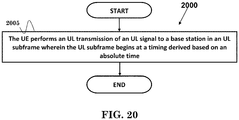
- FIG. 20 is a flow chart 2000 according to one exemplary embodiment from the perspective of a UE.
- the UE performs an UL transmission of an UL signal to a base station in an UL subframe wherein the UL subframe begins at a timing derived based on an absolute time.
- the UE could receive an indication from the base station indicating the absolute time.
- the absolute time could be an absolute time when a DL subframe begins at a base station, or when the UL subframe begins at a base station.
- the UE could derive the timing based on a second absolute time which is based on a clock of the UE.
- the UE could derive a propagation delay based on the absolute time, or on a reception time.
- the reception time could be based on a clock of the UE or a Global Position System (GPS) time.
- the UE could derive the timing based on a propagation delay.
- the UE could derive the timing based on a difference between when the UL subframe begins at the base station and the propagation delay, or on a difference between UL timing and Downlink (DL) timing at the base station.
- the UE could derive the timing without a timing advance command from the base station.
- the UE could derive the timing based on the absolute time if the UE's clock is precise. However, the UE may not derive the timing based on the absolute time if the UE's clock is not precise.
- the absolute time could be based on a clock of the UE.
- the UL subframe could be an UL subframe at the UE.
- the absolute time may comprise one or more of time units.
- a time unit could be one of hour, minute, second, millisecond, microsecond or nanosecond.
- the absolute time could be derived based on a timing difference between DL subframe and UL subframe at the base station.
- the absolute time could also be derived from a propagation delay between the base station and the UE.
- the absolute time could be derived by an absolute time when a UL subframe begins at a base station subtracting a propagation delay between a base station and the UE.
- the timing may not be derived based on a beginning of a DL subframe at the UE. Furthermore, the timing may not be derived relative to a beginning of a DL subframe at the UE. In addition, the timing may not be derived based on a synchronization procedure, or based on a random access procedure.
- the UE 300 includes a program code 312 stored in the memory 310.
- the CPU 308 could execute program code 312 to enable the UE to perform an UL transmission of an UL signal to a base station in an UL subframe wherein the UL subframe begins at a timing derived based on an absolute time. Furthermore, the CPU 308 can execute the program code 312 to perform all of the above-described actions and steps or others described herein.
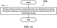
- FIG. 21 is a flow chart 2100 according to one exemplary embodiment from the perspective of a base station.
- the base station transmits a timing information to a UE wherein the timing information comprises an absolute time for the UE to determine the UE's UL transmission timing.
- the absolute time may be an absolute time when a DL subframe begins at a base station, or when the UL subframe begins at a base station.
- the absolute time could be used for deriving a propagation delay between the base station and the UE.
- the base station could indicate a difference between UL timing and Downlink (DL) timing at the base station to the UE.
- the base station may not send a timing advance command to the UE for determining the UE's UL transmission timing.
- the base station 300 includes a program code 312 stored in the memory 310.
- the CPU 308 could execute program code 312 to enable the base station to transmit a timing information to a UE wherein the timing information comprises an absolute time for the UE to determine the UE's UL transmission timing.
- the CPU 308 can execute the program code 312 to perform all of the above-described actions and steps or others described herein.
- concurrent channels may be established based on pulse repetition frequencies.
- concurrent channels may be established based on pulse position or offsets.
- concurrent channels may be established based on time hopping sequences.
- concurrent channels may be established based on pulse repetition frequencies, pulse positions or offsets, and time hopping sequences.
- the various illustrative logical blocks, modules, and circuits described in connection with the aspects disclosed herein may be implemented within or performed by an integrated circuit ("IC"), an access terminal, or an access point.
- the IC may comprise a general purpose processor, a digital signal processor (DSP), an application specific integrated circuit (ASIC), a field programmable gate array (FPGA) or other programmable logic device, discrete gate or transistor logic, discrete hardware components, electrical components, optical components, mechanical components, or any combination thereof designed to perform the functions described herein, and may execute codes or instructions that reside within the IC, outside of the IC, or both.
- a general purpose processor may be a microprocessor, but in the alternative, the processor may be any conventional processor, controller, microcontroller, or state machine.
- a processor may also be implemented as a combination of computing devices, e.g., a combination of a DSP and a microprocessor, a plurality of microprocessors, one or more microprocessors in conjunction with a DSP core, or any other such configuration.
- a software module e.g., including executable instructions and related data
- other data may reside in a data memory such as RAM memory, flash memory, ROM memory, EPROM memory, EEPROM memory, registers, a hard disk, a removable disk, a CD-ROM, or any other form of computer-readable storage medium known in the art.
- a sample storage medium may be coupled to a machine such as, for example, a computer/processor (which may be referred to herein, for convenience, as a "processor") such the processor can read information (e.g., code) from and write information to the storage medium.
- a sample storage medium may be integral to the processor.
- the processor and the storage medium may reside in an ASIC.
- the ASIC may reside in user equipment.
- the processor and the storage medium may reside as discrete components in user equipment.
- any suitable computer-program product may comprise a computer-readable medium comprising codes relating to one or more of the aspects of the disclosure.
- a computer program product may comprise packaging materials.
Landscapes
- Engineering & Computer Science (AREA)
- Computer Networks & Wireless Communication (AREA)
- Signal Processing (AREA)
- Quality & Reliability (AREA)
- Radar, Positioning & Navigation (AREA)
- Remote Sensing (AREA)
- Physics & Mathematics (AREA)
- General Physics & Mathematics (AREA)
- Mobile Radio Communication Systems (AREA)
Applications Claiming Priority (1)
| Application Number | Priority Date | Filing Date | Title |
|---|---|---|---|
| US201962935209P | 2019-11-14 | 2019-11-14 |
Publications (1)
| Publication Number | Publication Date |
|---|---|
| EP3826384A1 true EP3826384A1 (fr) | 2021-05-26 |
Family
ID=73401326
Family Applications (1)
| Application Number | Title | Priority Date | Filing Date |
|---|---|---|---|
| EP20207072.8A Pending EP3826384A1 (fr) | 2019-11-14 | 2020-11-12 | Procédé et appareil de détermination de synchronisation de liaison montante dans un système de communication sans fil |
Country Status (4)
| Country | Link |
|---|---|
| US (1) | US20210153193A1 (fr) |
| EP (1) | EP3826384A1 (fr) |
| KR (3) | KR20210059639A (fr) |
| CN (1) | CN112804745B (fr) |
Families Citing this family (33)
| Publication number | Priority date | Publication date | Assignee | Title |
|---|---|---|---|---|
| EP4108021A4 (fr) * | 2020-02-19 | 2023-03-29 | ZTE Corporation | Système et procédé de relation de synchronisation de liaison descendante - liaison montante |
| WO2021181128A1 (fr) * | 2020-03-13 | 2021-09-16 | Orope France Sarl | Appareil et procédé de communication associé |
| CN115802476A (zh) * | 2020-03-23 | 2023-03-14 | Oppo广东移动通信有限公司 | 一种ta确定方法及装置、终端设备 |
| US12004142B2 (en) * | 2020-03-30 | 2024-06-04 | Qualcomm Incorporated | Uplink timing associated with uplink transmission configuration indication (TCI) state |
| EP3893588B1 (fr) * | 2020-04-10 | 2022-08-31 | ASUSTek Computer Inc. | Procédé d'équipement d'utilisateur, équipement d'utilisateur et support non transitoire lisible par ordinateur pour une procédure d'accès aléatoire de récupération en cas de défaillance du faisceau de cellules secondaires dans un système de communication sans fil |
| US12273874B2 (en) * | 2020-04-24 | 2025-04-08 | Qualcomm Incorporated | Demodulation reference signal (DMRS) and sounding reference signal (SRS) bundling under uplink timing advance (TA) |
| EP4156804A4 (fr) * | 2020-05-22 | 2024-03-06 | Ntt Docomo, Inc. | Terminal et procédé exécuté par le terminal |
| WO2022021353A1 (fr) * | 2020-07-31 | 2022-02-03 | 北京小米移动软件有限公司 | Procédé et appareil d'envoi d'avance temporelle |
| EP4193780A1 (fr) * | 2020-08-06 | 2023-06-14 | Telefonaktiebolaget LM Ericsson (publ) | Définition de fenêtre de réponse rar dans un réseau ntn |
| KR20220018824A (ko) * | 2020-08-07 | 2022-02-15 | 삼성전자주식회사 | 통신 시스템에서 스케줄링 타이밍 결정 방법 및 장치 |
| US20220070811A1 (en) * | 2020-08-31 | 2022-03-03 | Samsung Electronics Co., Ltd. | Management of ephemeris, time, delays, and ta for an ntn |
| US11895603B2 (en) * | 2020-11-25 | 2024-02-06 | Electronics And Telecommunications Research Institute | Frame structure and terminal synchronization method and apparatus in wireless communication system |
| WO2022152297A1 (fr) * | 2021-01-18 | 2022-07-21 | Telefonaktiebolaget Lm Ericsson (Publ) | Procédé et appareil d'avance de temporisation |
| EP4315656B1 (fr) * | 2021-03-31 | 2025-04-23 | Sony Group Corporation | Procédés, dispositif de communication et équipement d'infrastructure pour un réseau non terrestre |
| US11864142B2 (en) * | 2021-03-31 | 2024-01-02 | FG Innovation Company Limited | User equipment and method for timing alignment |
| KR20230170085A (ko) * | 2021-05-06 | 2023-12-18 | 텔레폰악티에볼라겟엘엠에릭슨(펍) | 업링크 전송 타이밍 제어 |
| WO2022236490A1 (fr) * | 2021-05-08 | 2022-11-17 | Apple Inc. | Instant de reprise après défaillance de faisceau dans un réseau non terrestre (ntn) |
| WO2022240133A1 (fr) * | 2021-05-10 | 2022-11-17 | Samsung Electronics Co., Ltd. | Procédé et appareil pour déterminer et appliquer une avance temporelle dans un système de communication |
| US11997629B2 (en) * | 2021-05-11 | 2024-05-28 | Qualcomm Incorporated | Timing offset selection in non-terrestrial network |
| WO2022241351A1 (fr) | 2021-05-11 | 2022-11-17 | Qualcomm Incorporated | Sélection de décalage temporel dans un réseau non terrestre |
| WO2023000146A1 (fr) * | 2021-07-19 | 2023-01-26 | Oppo广东移动通信有限公司 | Procédé et appareil de configuration de porteuse, dispositif terminal et dispositif de réseau |
| US20230043974A1 (en) * | 2021-08-04 | 2023-02-09 | Qualcomm Incorporated | Method for defining uplink (ul) transmission timing accuracy |
| JP7667881B2 (ja) * | 2021-08-05 | 2025-04-23 | 中興通訊股▲ふん▼有限公司 | 時間同期技術 |
| US20230131305A1 (en) * | 2021-10-22 | 2023-04-27 | Samsung Electronics Co., Ltd. | Method and apparatus for timing advance adjustment |
| CN117813878A (zh) * | 2021-11-03 | 2024-04-02 | Oppo广东移动通信有限公司 | 定时器参数的确定方法、装置、设备及存储介质 |
| CN116419385A (zh) * | 2021-12-30 | 2023-07-11 | 华为技术有限公司 | 一种上行定时方法及相关装置 |
| CN116634546A (zh) * | 2022-02-11 | 2023-08-22 | 北京三星通信技术研究有限公司 | 无线通信系统中的方法和设备 |
| CN118743279A (zh) * | 2022-02-28 | 2024-10-01 | 高通股份有限公司 | 定时提前偏置配置 |
| KR20230159103A (ko) * | 2022-05-13 | 2023-11-21 | 삼성전자주식회사 | 위성 통신 시스템에서 데이터를 송수신하는 방법 및 장치 |
| US12484054B2 (en) | 2022-05-26 | 2025-11-25 | Outdoor Wireless Networks LLC | Dual base station frame boundaries |
| CN120858626A (zh) * | 2023-03-21 | 2025-10-28 | 华为技术有限公司 | 用于帧定时的定时指示的系统和方案 |
| US20240334405A1 (en) * | 2023-04-03 | 2024-10-03 | Nokia Technologies Oy | Multiple timing advance operation |
| EP4443992A1 (fr) * | 2023-04-03 | 2024-10-09 | Nokia Technologies Oy | Opération d'avance de synchronisation multiple |
Citations (2)
| Publication number | Priority date | Publication date | Assignee | Title |
|---|---|---|---|---|
| EP3297343A2 (fr) * | 2016-09-19 | 2018-03-21 | ASUSTek Computer Inc. | Procédé et appareil de gestion d'une avance de la temporisation pour la transmission en liaison montante dans un système de communications sans fil |
| US20180124724A1 (en) * | 2016-11-01 | 2018-05-03 | Asustek Computer Inc. | Method and apparatus for identifying uplink timing advance in a wireless communication system |
Family Cites Families (22)
| Publication number | Priority date | Publication date | Assignee | Title |
|---|---|---|---|---|
| US6252543B1 (en) * | 1998-05-28 | 2001-06-26 | Ericsson Inc. | Location system combining ranging measurements from GPS and cellular networks |
| US6188351B1 (en) * | 1998-08-13 | 2001-02-13 | Ericsson Inc. | Method for improving signal acquistion in a global positioning system receiver |
| US6678510B2 (en) * | 2001-02-05 | 2004-01-13 | Nokia Mobile Phones Ltd. | Method, apparatus and system for GPS time synchronization using cellular signal bursts |
| US20040080454A1 (en) * | 2002-10-23 | 2004-04-29 | Camp William O. | Methods and systems for determining the position of a mobile terminal using digital television signals |
| KR20040069444A (ko) * | 2003-01-29 | 2004-08-06 | 삼성전자주식회사 | 무선 단말기의 위치 정보를 획득하기 위한 무선 통신시스템 및 그 방법 |
| US7397365B2 (en) * | 2005-11-21 | 2008-07-08 | Lucent Technologies Inc. | Vehicle speeding alert system for GPS enabled wireless devices |
| US8451819B2 (en) * | 2008-03-26 | 2013-05-28 | Qualcomm Incorporated | Methods and apparatus for uplink frame synchronization in a subscriber station |
| KR101456001B1 (ko) * | 2008-05-23 | 2014-11-03 | 엘지전자 주식회사 | 단말기 및 그 제어 방법 |
| JP2010032256A (ja) * | 2008-07-25 | 2010-02-12 | Seiko Epson Corp | 衛星軌道データの圧縮方法、衛星軌道データの提供方法、衛星軌道データの展開方法、サーバ及び測位装置 |
| US9392521B2 (en) * | 2009-03-18 | 2016-07-12 | Telecommunication Systems, Inc. | System and method for concurrently determining locations of mobile device in wireless communication network |
| EP2622923A1 (fr) * | 2010-09-27 | 2013-08-07 | Fujitsu Limited | Porteuses radio pour communication de type machine |
| US8473196B2 (en) * | 2011-02-11 | 2013-06-25 | GM Global Technology Operations LLC | Use of self and neighboring vehicle GPS/GNSS data to estimate current and approaching sky visibility changes |
| US8805410B2 (en) * | 2011-11-16 | 2014-08-12 | Maple Acquisition Llc | Enhancing A-GPS location accuracy and yield with location measurement units and network timing measurements |
| US9402232B2 (en) * | 2013-05-10 | 2016-07-26 | Mediatek Inc. | Cell reselection enhancement for power saving LTE devices |
| US20180188698A1 (en) * | 2015-06-10 | 2018-07-05 | Smart Energy Instruments Inc. | Accurate time recovery from global navigation satellite system |
| TWI823214B (zh) * | 2015-08-25 | 2023-11-21 | 美商內數位專利控股公司 | 無線傳輸/接收單元及由其執行的方法 |
| WO2017204702A1 (fr) * | 2016-05-24 | 2017-11-30 | Telefonaktiebolaget Lm Ericsson (Publ) | Procédé et premier nœud de réseau pour le maintien de synchronisation temporelle |
| WO2018021824A1 (fr) * | 2016-07-26 | 2018-02-01 | 엘지전자 주식회사 | Procédé de transmission de signal de liaison montante et équipement utilisateur, et procédé de réception de signal de liaison montante et station de base |
| US10694562B2 (en) * | 2017-09-18 | 2020-06-23 | Apple Inc. | Off grid radio service system design |
| CN110278612B (zh) * | 2018-03-16 | 2022-07-12 | 华硕电脑股份有限公司 | 无线通信中处理多个无线电资源控制程序的方法和设备 |
| KR20250057950A (ko) * | 2019-01-11 | 2025-04-29 | 지티이 코포레이션 | 유휴 모드에서 전용 자원들을 사전 구성하기 위한 정보 전송 |
| US11515937B2 (en) * | 2019-08-22 | 2022-11-29 | Skylo Technologies, Inc. | Hub communication with a satellite network or a terrestrial network |
-
2020
- 2020-11-12 US US17/096,124 patent/US20210153193A1/en active Pending
- 2020-11-12 KR KR1020200150968A patent/KR20210059639A/ko not_active Ceased
- 2020-11-12 EP EP20207072.8A patent/EP3826384A1/fr active Pending
- 2020-11-12 CN CN202011261053.0A patent/CN112804745B/zh active Active
-
2023
- 2023-04-05 KR KR1020230044579A patent/KR20230050299A/ko not_active Ceased
-
2025
- 2025-03-18 KR KR1020250034500A patent/KR20250040928A/ko active Pending
Patent Citations (2)
| Publication number | Priority date | Publication date | Assignee | Title |
|---|---|---|---|---|
| EP3297343A2 (fr) * | 2016-09-19 | 2018-03-21 | ASUSTek Computer Inc. | Procédé et appareil de gestion d'une avance de la temporisation pour la transmission en liaison montante dans un système de communications sans fil |
| US20180124724A1 (en) * | 2016-11-01 | 2018-05-03 | Asustek Computer Inc. | Method and apparatus for identifying uplink timing advance in a wireless communication system |
Non-Patent Citations (8)
| Title |
|---|
| "Final Report of 3GPP TSG RAN WG1 #98", RL-1911249, 26 August 2019 (2019-08-26) |
| "Final Report of 3GPP TSG RAN WG1 #98bis", RL-1913275, 14 October 2019 (2019-10-14) |
| "NR; Medium Access Control (MAC) protocol specification (Release 15", TS 38.321, September 2019 (2019-09-01) |
| "NR; Physical channels and modulation (Release 15", TS 38.211, September 2019 (2019-09-01) |
| "NR; Physical layer procedures for control (Release 15", TS 38.213, September 2019 (2019-09-01) |
| "NR; Physical layer procedures for data (Release 15", TS 38.214, September 2019 (2019-09-01) |
| "Solutions for NR to support non-terrestrial networks (NTN) (Release 16", TS 38.821, May 2019 (2019-05-01) |
| CATT: "Discussion on Timing Advance Measurement for Positioning", 3GPP DRAFT; R4-092859_DISCUSSION OF TIMING ADVANCE MEASUREMENT FOR POSITIONING, 3RD GENERATION PARTNERSHIP PROJECT (3GPP), MOBILE COMPETENCE CENTRE ; 650, ROUTE DES LUCIOLES ; F-06921 SOPHIA-ANTIPOLIS CEDEX ; FRANCE, no. Shenzhen, China; 20090818, 18 August 2009 (2009-08-18), XP050354026 * |
Also Published As
| Publication number | Publication date |
|---|---|
| KR20210059639A (ko) | 2021-05-25 |
| KR20250040928A (ko) | 2025-03-25 |
| US20210153193A1 (en) | 2021-05-20 |
| CN112804745A (zh) | 2021-05-14 |
| KR20230050299A (ko) | 2023-04-14 |
| CN112804745B (zh) | 2024-10-15 |
Similar Documents
| Publication | Publication Date | Title |
|---|---|---|
| EP3826384A1 (fr) | Procédé et appareil de détermination de synchronisation de liaison montante dans un système de communication sans fil | |
| EP3609097B1 (fr) | Procédé et appareil permettant d'estimer la perte de trajet de pusch dans un système de communication sans fil | |
| US20220232505A1 (en) | Random Access Preambles Using Transmit Beams of Base Station | |
| EP3800822B1 (fr) | Procédé et appareil pour un grand retard de propagation dans un système de communication sans fil | |
| US11006456B2 (en) | Method and apparatus for transmitting and receiving random access channel | |
| JP6625170B2 (ja) | 無線通信システムにおけるsfi(スロットフォーマット情報)衝突を処理するための方法及び装置 | |
| US11395341B2 (en) | Method for performing random access process and device therefor | |
| US11395344B2 (en) | Method for transmitting and receiving random access channel and uplink channel in non-licensed band and apparatus therefor | |
| EP3609283A2 (fr) | Procédé et appareil d'indication de format de créneau pour un créneau final dans un spectre sans licence dans un système de communication sans fil | |
| JP7240328B2 (ja) | ランダム接続過程を行う方法及びそのための装置 | |
| US11375546B2 (en) | Terminal device, base station device, and communication method for performing random access procedure | |
| US11166322B2 (en) | Method for performing random access process and apparatus therefor | |
| EP3506713A1 (fr) | Procédé et appareil pour la sélection d'une partie de bande passante pour une procédure d'accès aléatoire (ra) dans un système de communication sans fil | |
| EP3525542A1 (fr) | Procédé et appareil de surveillance d'une indication de transmission interrompue dans un système de communication sans fil | |
| US10708947B2 (en) | Timing advance in LBT systems | |
| EP3316632A1 (fr) | Procédé et appareil dans un système de communication sans fil pour identifier une avance de temporisation de liaison montante reçue via une réponse d'accès aléatoire d'une procédure d'accès aléatoire dans une cellule. | |
| EP3340724B1 (fr) | Terminal d'utilisateur et procédé de communication sans fil | |
| CN115720381A (zh) | 发送和接收随机接入信道的方法及其装置 | |
| US20240334281A1 (en) | Communications for Handover Operations in Non-Terrestrial Networks | |
| KR20180050214A (ko) | 무선 통신에서 멀티 빔 기반 랜덤 액세스 절차를 수행하는 방법 및 장치 | |
| EP4598160A1 (fr) | Dispositif terminal, dispositif de station de base et procédé de communication | |
| EP4510719A1 (fr) | Dispositif terminal, dispositif de station de base et procédé de communication | |
| EP4510718A1 (fr) | Dispositif terminal, dispositif de station de base et procédé de communication | |
| US20260088950A1 (en) | User equipments, base stations and methods | |
| WO2025155649A1 (fr) | Ressource de référence d'informations d'état de canal |
Legal Events
| Date | Code | Title | Description |
|---|---|---|---|
| PUAI | Public reference made under article 153(3) epc to a published international application that has entered the european phase |
Free format text: ORIGINAL CODE: 0009012 |
|
| STAA | Information on the status of an ep patent application or granted ep patent |
Free format text: STATUS: THE APPLICATION HAS BEEN PUBLISHED |
|
| AK | Designated contracting states |
Kind code of ref document: A1 Designated state(s): AL AT BE BG CH CY CZ DE DK EE ES FI FR GB GR HR HU IE IS IT LI LT LU LV MC MK MT NL NO PL PT RO RS SE SI SK SM TR |
|
| STAA | Information on the status of an ep patent application or granted ep patent |
Free format text: STATUS: REQUEST FOR EXAMINATION WAS MADE |
|
| 17P | Request for examination filed |
Effective date: 20211029 |
|
| RBV | Designated contracting states (corrected) |
Designated state(s): AL AT BE BG CH CY CZ DE DK EE ES FI FR GB GR HR HU IE IS IT LI LT LU LV MC MK MT NL NO PL PT RO RS SE SI SK SM TR |
|
| STAA | Information on the status of an ep patent application or granted ep patent |
Free format text: STATUS: EXAMINATION IS IN PROGRESS |
|
| 17Q | First examination report despatched |
Effective date: 20230503 |