EP3826801B1 - Découpe de plancher et son procédé de fabrication - Google Patents
Découpe de plancher et son procédé de fabrication Download PDFInfo
- Publication number
- EP3826801B1 EP3826801B1 EP19736634.7A EP19736634A EP3826801B1 EP 3826801 B1 EP3826801 B1 EP 3826801B1 EP 19736634 A EP19736634 A EP 19736634A EP 3826801 B1 EP3826801 B1 EP 3826801B1
- Authority
- EP
- European Patent Office
- Prior art keywords
- cutting
- layer
- flooring
- floor
- sheet
- Prior art date
- Legal status (The legal status is an assumption and is not a legal conclusion. Google has not performed a legal analysis and makes no representation as to the accuracy of the status listed.)
- Active
Links
Images

Classifications
-
- E—FIXED CONSTRUCTIONS
- E04—BUILDING
- E04F—FINISHING WORK ON BUILDINGS, e.g. STAIRS, FLOORS
- E04F15/00—Flooring
- E04F15/02—Flooring or floor layers composed of a number of similar elements
- E04F15/0215—Flooring or floor layers composed of a number of similar elements specially adapted for being adhesively fixed to an underlayer; Fastening means therefor; Fixing by means of plastics materials hardening after application
-
- B—PERFORMING OPERATIONS; TRANSPORTING
- B23—MACHINE TOOLS; METAL-WORKING NOT OTHERWISE PROVIDED FOR
- B23K—SOLDERING OR UNSOLDERING; WELDING; CLADDING OR PLATING BY SOLDERING OR WELDING; CUTTING BY APPLYING HEAT LOCALLY, e.g. FLAME CUTTING; WORKING BY LASER BEAM
- B23K26/00—Working by laser beam, e.g. welding, cutting or boring
- B23K26/36—Removing material
- B23K26/38—Removing material by boring or cutting
-
- B—PERFORMING OPERATIONS; TRANSPORTING
- B32—LAYERED PRODUCTS
- B32B—LAYERED PRODUCTS, i.e. PRODUCTS BUILT-UP OF STRATA OF FLAT OR NON-FLAT, e.g. CELLULAR OR HONEYCOMB, FORM
- B32B27/00—Layered products comprising a layer of synthetic resin
- B32B27/12—Layered products comprising a layer of synthetic resin next to a fibrous or filamentary layer
-
- B—PERFORMING OPERATIONS; TRANSPORTING
- B32—LAYERED PRODUCTS
- B32B—LAYERED PRODUCTS, i.e. PRODUCTS BUILT-UP OF STRATA OF FLAT OR NON-FLAT, e.g. CELLULAR OR HONEYCOMB, FORM
- B32B27/00—Layered products comprising a layer of synthetic resin
- B32B27/32—Layered products comprising a layer of synthetic resin comprising polyolefins
-
- B—PERFORMING OPERATIONS; TRANSPORTING
- B32—LAYERED PRODUCTS
- B32B—LAYERED PRODUCTS, i.e. PRODUCTS BUILT-UP OF STRATA OF FLAT OR NON-FLAT, e.g. CELLULAR OR HONEYCOMB, FORM
- B32B27/00—Layered products comprising a layer of synthetic resin
- B32B27/36—Layered products comprising a layer of synthetic resin comprising polyesters
-
- B—PERFORMING OPERATIONS; TRANSPORTING
- B32—LAYERED PRODUCTS
- B32B—LAYERED PRODUCTS, i.e. PRODUCTS BUILT-UP OF STRATA OF FLAT OR NON-FLAT, e.g. CELLULAR OR HONEYCOMB, FORM
- B32B27/00—Layered products comprising a layer of synthetic resin
- B32B27/40—Layered products comprising a layer of synthetic resin comprising polyurethanes
-
- B—PERFORMING OPERATIONS; TRANSPORTING
- B32—LAYERED PRODUCTS
- B32B—LAYERED PRODUCTS, i.e. PRODUCTS BUILT-UP OF STRATA OF FLAT OR NON-FLAT, e.g. CELLULAR OR HONEYCOMB, FORM
- B32B29/00—Layered products comprising a layer of paper or cardboard
- B32B29/02—Layered products comprising a layer of paper or cardboard next to a fibrous or filamentary layer
-
- B—PERFORMING OPERATIONS; TRANSPORTING
- B32—LAYERED PRODUCTS
- B32B—LAYERED PRODUCTS, i.e. PRODUCTS BUILT-UP OF STRATA OF FLAT OR NON-FLAT, e.g. CELLULAR OR HONEYCOMB, FORM
- B32B3/00—Layered products comprising a layer with external or internal discontinuities or unevennesses, or a layer of non-planar shape; Layered products comprising a layer having particular features of form
- B32B3/02—Layered products comprising a layer with external or internal discontinuities or unevennesses, or a layer of non-planar shape; Layered products comprising a layer having particular features of form characterised by features of form at particular places, e.g. in edge regions
-
- B—PERFORMING OPERATIONS; TRANSPORTING
- B32—LAYERED PRODUCTS
- B32B—LAYERED PRODUCTS, i.e. PRODUCTS BUILT-UP OF STRATA OF FLAT OR NON-FLAT, e.g. CELLULAR OR HONEYCOMB, FORM
- B32B5/00—Layered products characterised by the non- homogeneity or physical structure, i.e. comprising a fibrous, filamentary, particulate or foam layer; Layered products characterised by having a layer differing constitutionally or physically in different parts
- B32B5/02—Layered products characterised by the non- homogeneity or physical structure, i.e. comprising a fibrous, filamentary, particulate or foam layer; Layered products characterised by having a layer differing constitutionally or physically in different parts characterised by structural features of a fibrous or filamentary layer
-
- E—FIXED CONSTRUCTIONS
- E04—BUILDING
- E04F—FINISHING WORK ON BUILDINGS, e.g. STAIRS, FLOORS
- E04F15/00—Flooring
- E04F15/02—Flooring or floor layers composed of a number of similar elements
- E04F15/10—Flooring or floor layers composed of a number of similar elements of other materials, e.g. fibrous or chipped materials, organic plastics, magnesite tiles, hardboard, or with a top layer of other materials
- E04F15/105—Flooring or floor layers composed of a number of similar elements of other materials, e.g. fibrous or chipped materials, organic plastics, magnesite tiles, hardboard, or with a top layer of other materials of organic plastics with or without reinforcements or filling materials
-
- B—PERFORMING OPERATIONS; TRANSPORTING
- B23—MACHINE TOOLS; METAL-WORKING NOT OTHERWISE PROVIDED FOR
- B23K—SOLDERING OR UNSOLDERING; WELDING; CLADDING OR PLATING BY SOLDERING OR WELDING; CUTTING BY APPLYING HEAT LOCALLY, e.g. FLAME CUTTING; WORKING BY LASER BEAM
- B23K2103/00—Materials to be soldered, welded or cut
- B23K2103/16—Composite materials
- B23K2103/166—Multilayered materials
-
- B—PERFORMING OPERATIONS; TRANSPORTING
- B23—MACHINE TOOLS; METAL-WORKING NOT OTHERWISE PROVIDED FOR
- B23K—SOLDERING OR UNSOLDERING; WELDING; CLADDING OR PLATING BY SOLDERING OR WELDING; CUTTING BY APPLYING HEAT LOCALLY, e.g. FLAME CUTTING; WORKING BY LASER BEAM
- B23K2103/00—Materials to be soldered, welded or cut
- B23K2103/30—Organic materials
- B23K2103/42—Plastics other than composite materials
-
- B—PERFORMING OPERATIONS; TRANSPORTING
- B32—LAYERED PRODUCTS
- B32B—LAYERED PRODUCTS, i.e. PRODUCTS BUILT-UP OF STRATA OF FLAT OR NON-FLAT, e.g. CELLULAR OR HONEYCOMB, FORM
- B32B2260/00—Layered product comprising an impregnated, embedded, or bonded layer wherein the layer comprises an impregnation, embedding, or binder material
- B32B2260/02—Composition of the impregnated, bonded or embedded layer
- B32B2260/021—Fibrous or filamentary layer
-
- B—PERFORMING OPERATIONS; TRANSPORTING
- B32—LAYERED PRODUCTS
- B32B—LAYERED PRODUCTS, i.e. PRODUCTS BUILT-UP OF STRATA OF FLAT OR NON-FLAT, e.g. CELLULAR OR HONEYCOMB, FORM
- B32B2260/00—Layered product comprising an impregnated, embedded, or bonded layer wherein the layer comprises an impregnation, embedding, or binder material
- B32B2260/04—Impregnation, embedding, or binder material
- B32B2260/046—Synthetic resin
-
- B—PERFORMING OPERATIONS; TRANSPORTING
- B32—LAYERED PRODUCTS
- B32B—LAYERED PRODUCTS, i.e. PRODUCTS BUILT-UP OF STRATA OF FLAT OR NON-FLAT, e.g. CELLULAR OR HONEYCOMB, FORM
- B32B2262/00—Composition or structural features of fibres which form a fibrous or filamentary layer or are present as additives
- B32B2262/02—Synthetic macromolecular fibres
- B32B2262/0276—Polyester fibres
-
- B—PERFORMING OPERATIONS; TRANSPORTING
- B32—LAYERED PRODUCTS
- B32B—LAYERED PRODUCTS, i.e. PRODUCTS BUILT-UP OF STRATA OF FLAT OR NON-FLAT, e.g. CELLULAR OR HONEYCOMB, FORM
- B32B2262/00—Composition or structural features of fibres which form a fibrous or filamentary layer or are present as additives
- B32B2262/10—Inorganic fibres
- B32B2262/101—Glass fibres
-
- B—PERFORMING OPERATIONS; TRANSPORTING
- B32—LAYERED PRODUCTS
- B32B—LAYERED PRODUCTS, i.e. PRODUCTS BUILT-UP OF STRATA OF FLAT OR NON-FLAT, e.g. CELLULAR OR HONEYCOMB, FORM
- B32B2307/00—Properties of the layers or laminate
- B32B2307/40—Properties of the layers or laminate having particular optical properties
- B32B2307/412—Transparent
-
- B—PERFORMING OPERATIONS; TRANSPORTING
- B32—LAYERED PRODUCTS
- B32B—LAYERED PRODUCTS, i.e. PRODUCTS BUILT-UP OF STRATA OF FLAT OR NON-FLAT, e.g. CELLULAR OR HONEYCOMB, FORM
- B32B2307/00—Properties of the layers or laminate
- B32B2307/70—Other properties
- B32B2307/718—Weight, e.g. weight per square meter
-
- B—PERFORMING OPERATIONS; TRANSPORTING
- B32—LAYERED PRODUCTS
- B32B—LAYERED PRODUCTS, i.e. PRODUCTS BUILT-UP OF STRATA OF FLAT OR NON-FLAT, e.g. CELLULAR OR HONEYCOMB, FORM
- B32B2307/00—Properties of the layers or laminate
- B32B2307/70—Other properties
- B32B2307/732—Dimensional properties
-
- B—PERFORMING OPERATIONS; TRANSPORTING
- B32—LAYERED PRODUCTS
- B32B—LAYERED PRODUCTS, i.e. PRODUCTS BUILT-UP OF STRATA OF FLAT OR NON-FLAT, e.g. CELLULAR OR HONEYCOMB, FORM
- B32B2419/00—Buildings or parts thereof
- B32B2419/04—Tiles for floors or walls
-
- B—PERFORMING OPERATIONS; TRANSPORTING
- B32—LAYERED PRODUCTS
- B32B—LAYERED PRODUCTS, i.e. PRODUCTS BUILT-UP OF STRATA OF FLAT OR NON-FLAT, e.g. CELLULAR OR HONEYCOMB, FORM
- B32B2471/00—Floor coverings
Definitions
- the invention relates to a floor blank according to the preamble of claim 1 (see e.g U.S. 2011/200750 A1 ), and a method for producing such floor blanks from a floor sheet.
- Floor cuts are used, for example, as adhesive goods that are glued to a subfloor in order to create a floor covering.
- Punching tools are also used for cutting. Like the cutting tools, these are also subject to tool wear.
- the U.S. 2014/054275 A1 discloses a technology for manufacturing a cutting tool.
- a predefined profile of the cutting tool is set using a laser.
- a laser beam forms a rounded edge on the side of the tool where the laser beam enters.
- a sharp edge is formed on a side of the tool where the laser beam exits.
- the U.S. 2003/218278 A1 discloses a method for dividing multilayer films and laminated bodies by means of laser radiation.
- cutting lines are cut into the laminate body, so that the laminate body is divided into several discrete pieces. It is provided that the cutting line has a rounded edge directed towards the surface of the laminate body.
- the U.S. 4,469,931A discloses a method of cutting wood or plastic to eliminate chipping or chips. First, a notch is cut into the material surface using a laser beam. The material is then cut with a saw along the notch created by the laser radiation. By previously using laser burned-in notch reduces the formation of chips during the subsequent sawing process.
- the cutting into several floor blanks and the subsequent production of the profiled contour is associated with a certain manufacturing effort.
- the invention is therefore based on the object of providing a floor blank which has at least one profiled edge and is easy to manufacture.
- the floor blank according to the invention has a multi-layer structure, which has a wear layer made of a transparent plastic, a decorative layer, a reinforcement layer and a carrier layer, and with at least one edge that extends from a wear surface to a back of the floor blank and on which a profiled contour is provided.
- the profiled contour has a rounding or chamfer in an upper area or in the area of the useful surface.
- the profiled contour forms an undercut in a lower area of the floor blank.
- the profiled contour is produced entirely by a laser tool with a cutting nozzle, the longitudinal axis of which is aligned perpendicularly to the useful surface when the profiled contour is produced.
- Thermosetting plastics are preferred as the plastic for the wear layer such as polyurethane.
- thermoplastics also come into play Plastics such as PVC, PP, PE or PET in question.
- Plastics such as PU or PVC can also be used as the material for the carrier layer.
- the chamfer or rounding of the edge merges into a convex contact curve. In the case of floor cuts with the same (cut) edge in each case, the respective contact curves of the opposite edges come into contact.
- the convex contact curvature can be provided at the height of the reinforcement layer.
- the chamfer or rounding can roughly correspond to the shape of a quadrant. A radius of this quadrant can be 50 to 700 ⁇ m. The radius of the quadrant preferably corresponds approximately to the thickness of the wear layer.
- the contact curvature is followed by an inclined, essentially rectilinear contour section.
- This straight contour section is in a middle to lower area of the edge.
- an angle of inclination to a main extension of the edge, which runs perpendicularly to the usable surface, is 2 to 10°, preferably 4 to 8°.
- the method according to the invention provides that the laser tool, preferably a CO 2 laser, is used for cutting the floor membrane into the floor blanks, by means of which the profiled contour is produced during the cutting in one operation. While in the production methods known from the prior art the cutting of the floor blanks and the production of the profiled contour mean two separate work steps, according to the invention only a single operation is required to divide the floor sheet into the floor blanks and to produce the profiled contour. Preferably a post-processing or that Attaching sub-contours to the profiled contour is no longer necessary after this combined work step.
- the term "cutting" is to be understood generally as cutting the floor sheet into the floor blanks.
- the laser tool can have a movable laser cutting head that follows a predetermined cutting line (plotter system).
- the floor sheet can be fixed and the laser cutting speed corresponds to the speed of the laser cutting head.
- Curved or arched edges can also be created with the moveable laser cutting head.
- rectangular floor blanks are produced with the method according to the invention, with two longitudinal edges preferably having the profiled contour.
- the transverse edges perpendicular to the longitudinal edges can also have a profiled contour produced by the laser tool.
- the floor sheet can also be cut into the floor sections by a plurality of stationary laser cutting heads of the laser tool, with a laser cutting speed during cutting corresponding to a transport speed of the floor sheet.
- the laser cutting head or a cutting nozzle of the laser cutting head is preferably directed vertically downwards, while the floor sheet is transported in a horizontal direction.
- the laser cutting speed i.e. the relative speed between the laser cutting head and the floor covering, can be 5 to 25 m per minute.
- a thickness of the floor sheet of 2 to 3 mm it is possible, for example, with a power consumption of the laser cutting head of 500 W, to achieve a laser cutting speed of 5 to 10 m per minute.
- a power consumption of 1000 W laser cutting speeds of 10 to 25 m per minute possible. If the power consumption is even higher, values over 25 m per minute can also be achieved.
- the laser cutting heads can be arranged next to one another on a carrier beam, which preferably extends transversely to the transport direction of the floor sheet.
- a floor strip is taken as a basis that has a strip width B of approx. 2 m and a strip length L of 130 cm, with the floor strip being fed to the laser tool along its strip length L (transport direction parallel to strip length L), then in one Produce ten floor cuts, each with a width of approx. 20 cm and a length L of 130 cm, when eleven fixed laser cutting heads are arranged next to each other for eleven longitudinal cuts. All floor cuts, including the floor cuts located at the edge, then have two profiled longitudinal edges. However, there are also two narrow edge waste strips.
- laser cutting heads it has proven to be cost-effective to allocate several laser cutting heads to one energy source. For example, three laser cutting heads with a preferred power consumption of 300 to 800 W each can be supplied by an energy source with a power of 2500 W. With eleven laser cutting heads, for example, four energy sources, each with 2500 W, would then be sufficient.
- the floor sheet is an endless sheet.
- This endless sheet can be, for example, a wound up endless sheet in the form of a roll. It is also possible for the production of the floor web or the endless web to take place immediately before the floor web is cut into the floor blanks, so that there is no need for the endless web to be rolled up or stored in another way in the meantime.
- the floor web is an endless web
- Endless cuts are necessary, which in principle can also be made by the laser tool.
- the laser tool can have additional laser cutting heads.
- the transverse cuts are made by a guillotine or guillotine, which preferably extends across the entire width of the continuous web. The transverse cuts can occur before or after the longitudinal cuts.
- the floor sheet can have a multi-layer structure, with a release layer being produced by applying a liquid polyurethane material to form a transparent wear layer, a decorative sheet to form a decorative layer (which is also intended to include a decorative continuous sheet) and a reinforcing material to form a reinforcing layer can.
- a release layer being produced by applying a liquid polyurethane material to form a transparent wear layer
- a decorative sheet to form a decorative layer (which is also intended to include a decorative continuous sheet)
- a reinforcing material to form a reinforcing layer
- Another plastic preferably also a polyurethane material, can be applied to form a carrier layer.
- the polyurethane material for the backing may include fillers.
- the release layer is again separated from the other layers, resulting in the following layer structure: transparent wear layer, decorative layer, reinforcement layer, carrier layer.
- the release layer can have an embossed surface with elevations and/or depressions. This gives the transparent wear layer a corresponding surface embossing.
- the polyurethane material for the transparent wear layer is preferably composed of aliphatic polyurethane components.
- the polyurethane material for the backing layer is preferably composed of aromatic polyurethane components.
- the decor sheet is a cellulose-based decor paper.
- the decorative sheet can also be a decorative film made from plastic, for example from PP, PE or PET.
- the basis weight of the decorative paper or the decorative film can be 20 to 100 g/m 2 .
- the reinforcement material may comprise a fiberglass mat. It can be, for example, a glass fiber mat, a glass fiber fabric or a glass fiber fabric.
- the polyurethane material for the carrier layer can contain organic or inorganic fillers.
- Sand, chalk, clay, minerals or glass can be used as inorganic fillers.
- Wood, cork, lignin, plant fibers can be used as organic fillers, or polystyrene or granules can be used as polymeric fillers.
- a liquid paper strengthener can be applied to a reverse side of the decal sheet.
- the paper strength agent can be a PU formulation that is preferably halogen-free.
- the paper strength agent may include a flame retardant.
- the flame retardant preferably has a mineral content.
- the backing material Before applying the paper strengthener to the back of the decal sheet, the backing material may be applied to the decal sheet.
- the liquid paper strengthener penetrates into the glass fiber mat and then gets into the decal sheet, as a result of which the decal sheet and glass fiber mat are correspondingly impregnated.
- figure 1 shows a perspective view of a floor blank 10. It is a rectangular floor blank with two parallel longitudinal edges 11, 12 and two transverse edges 13, 14 running perpendicular thereto.
- the length of the floor blank (corresponds to the length of the longitudinal edges 11, 12) can be 50 cm to 150 cm, for example, if it is a tile.
- the floor cut as a panel can have a length of 90 to 200 cm.
- a width of the floor blank 10 can be 25 to 100 cm for a tile and 15 to 25 cm for a panel (the width corresponds to the length of the transverse edges 13, 14).
- figure 1 shows the floor blank 10 only schematically: the edges 12, 13 are shown in simplified form as flat surfaces.
- figure 2 shows a cross section of the in figure 1 shown floor blank 10 along the section line II-II.
- the longitudinal edges 11, 12 each have a profiled contour 20, the profiled contour 20 of the longitudinal edge 12 being mirror-symmetrical to the profiled contour of the edge 11.
- the statements regarding the profiled contour 20 of the longitudinal edge 12 also apply accordingly to the profiled contour of the longitudinal edge 11.
- the profiled contour 20 has a chamfer or rounding 21 in the form of a quadrant in an upper area of the floor blank 10 , which transitions into a convex contact curve 22 .
- the contact curvature 22 is followed by a substantially rectilinear contour section 23 which extends to the underside 16 of the floor blank 10 .
- An angle of inclination between a main extension of the edge 12 (see dotted line 5) and the contour section 23 is denoted by 24 and is 6 to 8°.
- figure 2 shows the cross section of the surface blank 10 only schematically, so that angles, dimensions, thicknesses, etc. are not shown to scale.
- Out of figure 2 also shows the multi-layer structure 30 of the floor blank 10 .
- the structure has a transparent and possibly embossed wear layer 31 made of a polyurethane material with aliphatic polyurethane components. Seen from above, the wear layer 31 is followed by a decorative layer 32, which is mainly formed by a decorative sheet of decorative paper based on cellulose. Below the decorative layer 32 there is a reinforcement layer 33 with a glass fiber mat. A layer 34 is indicated below the reinforcing layer 33, which is intended to represent a paper strength agent in the form of a liquid polyurethane formulation.
- the PU formulation contains a flame retardant with a mineral content.
- the aliphatic polyurethane material is first applied to a horizontally extending release layer (not shown) to form the wear layer 31. This means that when the layer structure 30 is produced, the wear layer 31 represents the bottom layer onto which the other layers are applied.
- the decorative sheet and then the glass fiber mat are then placed on this polyurethane material from above to form the decorative layer 32 .
- the liquid PU formulation is then applied to the glass fiber mat, with the PU formulation penetrating the glass fiber mat and thus also impregnating the decal sheet.
- the polyurethane material for the wear layer also penetrates into the decal sheet, so that the decal sheet and, if necessary, the glass fiber mat are also impregnated from this side.
- the depiction of the paper strength agent 34 below the decorative layer 32 is intended to make it clear that in the preferred production of the layered structure 30, in which case the in figure 2 layer structure shown must be turned upside down, the paper strength agent is applied to the glass fiber mat.
- a highly filled polyurethane material is then placed on the paper strengthener 34, on which finally a polyester fleece 36 is placed.
- the liquid materials applied harden as a result of heat input.
- Heat is preferred introduced into the layer structure 30 exclusively from below, ie through the release layer. Heat can also be introduced into the layer structure 30 from above, for example by means of IR radiators.
- a preferred thickness of the floor blank 10, also independent of the specific layer structure, is 2 to 5 mm.
- the thickness of the wear layer 31 can be 50 to 500 ⁇ m.
- the thickness of the decorative layer 32, the reinforcing layer 33 and the paper strengthener 34 can all be 50 to 350 ⁇ m.
- a predominant part of the thickness of the floor blank 10 is accounted for by the carrier layer 35, which can be 1 to 5 mm, for example.
- the convex contact curvature 22 lies at a height of the layer structure 30 in which the reinforcement layer 33 or the decorative layer 32 is arranged.
- the straight contour section 23 extends practically over the entire height of the carrier layer 35.
- a horizontal extension 25 of the chamfer or rounding 21 corresponds approximately to the thickness of the wear layer 31, for example 250 to 350 ⁇ m.
- the horizontal extent 25 relates to a vertically running tangent (see dot-dash line 5), which is applied to the convex contact curvature 22. If the chamfer or rounding is designed as a quadrant, its radius can be approximately 250 to 350 ⁇ m.
- the convex contact curvature 22 and the inwardly drawn contour section 23 result in an undercut 26 which is delimited by the contour section 23 and the chain-dotted line 5 .
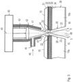
- figure 3 shows a laser cutting head 40 with a cutting nozzle 41.
- a lens 42 is enclosed in the cutting nozzle 41, through which laser beams 43 emerging in parallel from the laser cutting head 40 are bundled into a focus or focal point 44.
- a cutting gas 46 is supplied to the cutting nozzle 41 through a lateral opening 45 and emerges from the cutting nozzle 41 through a nozzle outlet opening 47 .
- an inert gas such as nitrogen is preferred.
- figure 3 10 also shows two floor blanks 10a, 10b which have been separated from one another by the laser cutting head 40. Due to the layer structure 30 comprising the wear layer 31 with the polyurethane material, the layered composite consisting of the decorative paper 32, the glass fiber mat 33 and the paper strengthener 34 with the flame retardant, and the carrier layer 35 made of a highly filled polyurethane and due to a vertical height adjustment of the cutting nozzle 41 in relation to the floor sections 10a, 10b, there is a cutting gap designated 48 with a constriction at the level of the reinforcement layer 33.
- a longitudinal axis 49 of the cutting nozzle 41 is aligned perpendicularly to the useful surface 15 of the floor sections 10a, 10b, so that a to the longitudinal axis 49 mirror-symmetrical configuration of the cutting gap 48 results.
- the shape of the cutting gap 48 thus defines the profiled contours 20 .
- the cutting nozzle 41 separates the floor sections 10a, 10b from above, ie. that the laser beam 43 hits the wear layer 31 first.
- FIG 3 the tangents (see dot-dash line 5) that are applied to the respective contact curvature 22 are also shown.
- the tangents 5 are intended to make it clear how the cutting gap 48 differs from a narrow, rectangular cutting gap which is delimited by the tangents 5 .
- a narrow rectangular cutting gap is not sought, as is usually the goal in laser cutting. Rather, a cutting gap 48 that differs significantly from this and is provided with a constriction is sought in order to obtain the desired profiled edges 20 of the floor blanks 10a, 10b.
- the vertical height of the focal point 44 coincides with the vertical height of the opposing bulges 22.
- the enveloping beams of the laser beam behind the focal point 44 are also drawn in as parallels to the inclined straight contour sections 23 .
- such a geometric constellation is not mandatory for the method according to the invention.
- the vertical height of the focal point can deviate from the vertical height of the attachment curves.
- the inclination of the straight contour sections can also deviate from the course of the enveloping beams of the laser beam. According to the invention, an approximately quarter-circle rounding results, which is delimited at the bottom by the decorative layer 32 or the reinforcement layer 33 .
Landscapes
- Engineering & Computer Science (AREA)
- Architecture (AREA)
- Civil Engineering (AREA)
- Structural Engineering (AREA)
- Physics & Mathematics (AREA)
- Optics & Photonics (AREA)
- Plasma & Fusion (AREA)
- Mechanical Engineering (AREA)
- Laser Beam Processing (AREA)
- Floor Finish (AREA)
Claims (11)
- Découpe de plancher (10) avec une structure (30) multicouche qui présente une couche utile (31) en une matière plastique transparente, une couche décorative (32), une couche de renforcement (33) et une couche porteuse (35), ainsi qu'avec au moins une arête (11, 12) qui s'étend d'une surface utile (15) jusqu'à un dos (16) de la découpe de plancher et au niveau de laquelle un contour profilé (20) est prévu, lequel présente un arrondi ou un chanfrein (21) dans la zone de la surface utile (31) et réalise dans une zone innférieure de la découpe de plancher une contre-dépouille (26), caractérisée en ce que le contour profilé est complètement fabriqué par un outil laser avec une douille de coupe (41), dont l'axe longitudinal (49) est orienté lors de la fabrication du contour profilé (20) perpendiculairement à la surface utile (15), dans laquelle le chanfrein ou l'arrondi (21) passe en une courbure d'appui (22) réalisée de manière convexe, et dans laquelle à la courbure d'appui (22) se raccorde une section de contour (23) inclinée sensiblement en ligne droite, dans laquelle la section de contour (23) en ligne droite s'étend jusqu'au dos (16) de la découpe de plancher (10).
- Procédé de fourniture de découpes de plancher (10) selon la revendication 1 à partir d'une bande de plancher, avec les étapes suivantes :A coupe de la bande de plancher en plusieurs découpes de plancher (10), dans lequel respectivement au moins l'arête (11, 12) apparaît au niveau des découpes de plancher (10) ;B fabrication du contour profilé (20) au niveau de l'arête (11, 12), dans lequel le contour (20) présente le chanfrein ou l'arrondi (21) au niveau d'une zone supérieure de l'arête et réalise la contre-dépouille (26) au niveau de la zone inférieure,dans lequel l'outil laser est utilisé pour la coupe de la bande de plancher, par lequel le contour (20) profilé est fabriqué lors de la coupe dans un cycle de travail.
- Procédé selon la revendication 2, caractérisé en ce que la coupe de la bande de plancher en découpes de plancher (10) est effectuée par une tête de coupe laser (40) mobile qui suit une ligne de coupe prédéterminée.
- Procédé selon la revendication 2 ou 3, caractérisé en ce que la découpe est effectuée par plusieurs têtes de coupe laser (40) fixes de l'outil laser.
- Procédé selon l'une quelconque des revendications 2 à 4, caractérisé en ce que la bande de plancher est une bande sans fin.
- Procédé selon la revendication 2, caractérisé en ce que la bande de plancher (10) est constituée en plusieurs couches et pour sa fabrication sur une couche de libération, du polyuréthane est appliqué pour la formation de la couche utile (31) transparente, pour la formation de la couche décorative (32) une feuille décorative et pour la formation de la couche de renforcement (33) un matériau de renforcement.
- Procédé selon la revendication 6, caractérisé en ce que pour la formation de la couche porteuse (35), du polyuréthane est appliqué avec une substance de remplissage.
- Procédé selon la revendication 6 ou 7, caractérisé en ce que le matériau de renforcement comporte un tapis de fibre de verre.
- Procédé selon l'une quelconque des revendications 6 à 8, caractérisé en ce qu'un agent de consolidation de papier (34) liquide est appliqué sur un côté arrière de la feuille décorative.
- Procédé selon la revendication 9, caractérisé en ce que l'agent de consolidation de papier comporte un agent ignifuge avec une part minérale.
- Procédé selon la revendication 9 ou 10, caractérisé en ce qu'avant l'application de l'agent de consolidation de papier (34) sur le côté arrière de la feuille décorative, le matériau de renforcement est appliqué.
Applications Claiming Priority (2)
| Application Number | Priority Date | Filing Date | Title |
|---|---|---|---|
| DE102018117755.0A DE102018117755A1 (de) | 2018-07-23 | 2018-07-23 | Fußbodenzuschnitt und Verfahren zu dessen Herstellung |
| PCT/EP2019/067394 WO2020020574A1 (fr) | 2018-07-23 | 2019-06-28 | Découpe de plancher et son procédé de fabrication |
Publications (3)
| Publication Number | Publication Date |
|---|---|
| EP3826801A1 EP3826801A1 (fr) | 2021-06-02 |
| EP3826801B1 true EP3826801B1 (fr) | 2023-08-23 |
| EP3826801C0 EP3826801C0 (fr) | 2023-08-23 |
Family
ID=67184988
Family Applications (1)
| Application Number | Title | Priority Date | Filing Date |
|---|---|---|---|
| EP19736634.7A Active EP3826801B1 (fr) | 2018-07-23 | 2019-06-28 | Découpe de plancher et son procédé de fabrication |
Country Status (3)
| Country | Link |
|---|---|
| EP (1) | EP3826801B1 (fr) |
| DE (1) | DE102018117755A1 (fr) |
| WO (1) | WO2020020574A1 (fr) |
Citations (1)
| Publication number | Priority date | Publication date | Assignee | Title |
|---|---|---|---|---|
| US20110200750A1 (en) * | 2008-11-13 | 2011-08-18 | Flooring Industries Limited, Sarl | Methods for manufacturing panels and panel obtained herewith |
Family Cites Families (7)
| Publication number | Priority date | Publication date | Assignee | Title |
|---|---|---|---|---|
| US4469931A (en) * | 1982-09-13 | 1984-09-04 | Macken John A | Laser assisted saw device |
| US20030218278A1 (en) * | 2002-05-21 | 2003-11-27 | Tait Bruce E. | Method for subdividing multilayer optical film cleanly and rapidly |
| SE526651C2 (sv) * | 2003-12-18 | 2005-10-18 | Pergo Europ Ab | Fog för panel innefattande på ovansidan anordnad fogprofil med snäpptungor |
| BE1016464A3 (nl) * | 2005-02-23 | 2006-11-07 | Flooring Ind Ltd | Werkwijze voor het vervaardigen van vloerpanelen, alsmede vloerpaneel dat door middel van zulke werkwijze is verkregen. |
| DE102005063034B4 (de) | 2005-12-29 | 2007-10-31 | Flooring Technologies Ltd. | Paneel, insbesondere Bodenpaneel |
| JP4976576B2 (ja) * | 2010-11-01 | 2012-07-18 | 住友電気工業株式会社 | 切削工具とその製造方法および製造装置 |
| DE202011107236U1 (de) * | 2011-10-28 | 2011-11-24 | Ulrich Windmöller Consulting GmbH | Fußbodenbelag |
-
2018
- 2018-07-23 DE DE102018117755.0A patent/DE102018117755A1/de active Pending
-
2019
- 2019-06-28 WO PCT/EP2019/067394 patent/WO2020020574A1/fr not_active Ceased
- 2019-06-28 EP EP19736634.7A patent/EP3826801B1/fr active Active
Patent Citations (1)
| Publication number | Priority date | Publication date | Assignee | Title |
|---|---|---|---|---|
| US20110200750A1 (en) * | 2008-11-13 | 2011-08-18 | Flooring Industries Limited, Sarl | Methods for manufacturing panels and panel obtained herewith |
Also Published As
| Publication number | Publication date |
|---|---|
| EP3826801A1 (fr) | 2021-06-02 |
| WO2020020574A1 (fr) | 2020-01-30 |
| DE102018117755A1 (de) | 2020-01-23 |
| EP3826801C0 (fr) | 2023-08-23 |
Similar Documents
| Publication | Publication Date | Title |
|---|---|---|
| EP1392481B1 (fr) | Procede de fabrication d'un element plat tridimensionnel deformable en flexion | |
| EP1808311B1 (fr) | Panneau, notamment panneau de plancher | |
| EP1754581B1 (fr) | Procédé de fabrication de panneaux | |
| EP3294510B1 (fr) | Procédé de fabrication de panneaux comportant des évidements | |
| EP1719596B1 (fr) | Procédé de fabrication d'un panneau de plancher | |
| EP1213118B1 (fr) | Panneaux en mousse d'épaisseur élévée | |
| EP1563970B1 (fr) | Procédé de fabrication de panneaux en bois ou matériaux de substitution du bois et panneau ainsi obtenu | |
| DE10106341B4 (de) | Kunststoffschaumplatten großer Dicke | |
| EP0733450A1 (fr) | Procédé et dispositif pour revêtir le cÔté étroit d'une pièce avec des matériaux en bois | |
| AT506045A1 (de) | Schalplatte | |
| DE3906594A1 (de) | Verfahren zur herstellung eines postforming-laminats | |
| DE2830935A1 (de) | Verfahren zur herstellung von bauelementen und -profilen aus ebenen platten und nach diesem verfahren hergestelltes bauelement | |
| EP3650184B1 (fr) | Procédé de fabrication de composants en bois plein, barre continue en bois plein destinée audit procédé et composant en bois plein fabriqué selon ledit procédé | |
| DE10241769B3 (de) | Verfahren zur Herstellung eines Nut-Feder-Profils an den Rändern von Fussbodenpaneelen | |
| EP3826801A1 (fr) | Découpe de plancher et son procédé de fabrication | |
| DE10224912A1 (de) | Vorrichtung und Verfahren zum Zusammenfügen mehrschichtiger Panele, sowie derartige Panele | |
| DE102004052931B3 (de) | Verfahren und Maschine zum Herstellen von formatierten Leichtbauplatten | |
| DE3041870A1 (de) | Kantenseitig mit einer deckschicht ausgestattetes bauteil und verfahren und vorrichtung zu seiner herstellung | |
| DE102005054608B3 (de) | Verfahren zur Bearbeitung der Schmalflächen von Sandwichbauteilen in Leichtbauweise und eine Vorrichtung zur Durchführung des Verfahrens | |
| DE102020006861A1 (de) | Verfahren und Anlage zur Herstellung von Werkstoffplatten | |
| DE102008004108B4 (de) | Paneel für einen Boden-, Wand- und/oder Deckenbelag sowie Verfahren zu dessen Herstellung | |
| DE102011002149B4 (de) | Verfahren zur Herstellung von Paneelen | |
| DE102009012695B4 (de) | Verfahren zur Herstellung eines Boden-, Wand- oder Deckenelementes, Vorrichtung zur Durchführung des Verfahrens und Plattenrohling für ein derartiges Element | |
| DE102017113368A1 (de) | Mehrschichtplatte und Verfahren zu ihrer Herstellung | |
| WO2023094367A1 (fr) | Élément plan tridimensionnel déformable en flexion et son procédé de fabrication |
Legal Events
| Date | Code | Title | Description |
|---|---|---|---|
| STAA | Information on the status of an ep patent application or granted ep patent |
Free format text: STATUS: UNKNOWN |
|
| STAA | Information on the status of an ep patent application or granted ep patent |
Free format text: STATUS: THE INTERNATIONAL PUBLICATION HAS BEEN MADE |
|
| PUAI | Public reference made under article 153(3) epc to a published international application that has entered the european phase |
Free format text: ORIGINAL CODE: 0009012 |
|
| STAA | Information on the status of an ep patent application or granted ep patent |
Free format text: STATUS: REQUEST FOR EXAMINATION WAS MADE |
|
| 17P | Request for examination filed |
Effective date: 20210111 |
|
| AK | Designated contracting states |
Kind code of ref document: A1 Designated state(s): AL AT BE BG CH CY CZ DE DK EE ES FI FR GB GR HR HU IE IS IT LI LT LU LV MC MK MT NL NO PL PT RO RS SE SI SK SM TR |
|
| DAV | Request for validation of the european patent (deleted) | ||
| DAX | Request for extension of the european patent (deleted) | ||
| STAA | Information on the status of an ep patent application or granted ep patent |
Free format text: STATUS: EXAMINATION IS IN PROGRESS |
|
| 17Q | First examination report despatched |
Effective date: 20220307 |
|
| GRAP | Despatch of communication of intention to grant a patent |
Free format text: ORIGINAL CODE: EPIDOSNIGR1 |
|
| STAA | Information on the status of an ep patent application or granted ep patent |
Free format text: STATUS: GRANT OF PATENT IS INTENDED |
|
| INTG | Intention to grant announced |
Effective date: 20230613 |
|
| GRAS | Grant fee paid |
Free format text: ORIGINAL CODE: EPIDOSNIGR3 |
|
| GRAA | (expected) grant |
Free format text: ORIGINAL CODE: 0009210 |
|
| STAA | Information on the status of an ep patent application or granted ep patent |
Free format text: STATUS: THE PATENT HAS BEEN GRANTED |
|
| AK | Designated contracting states |
Kind code of ref document: B1 Designated state(s): AL AT BE BG CH CY CZ DE DK EE ES FI FR GB GR HR HU IE IS IT LI LT LU LV MC MK MT NL NO PL PT RO RS SE SI SK SM TR |
|
| REG | Reference to a national code |
Ref country code: GB Ref legal event code: FG4D Free format text: NOT ENGLISH |
|
| REG | Reference to a national code |
Ref country code: CH Ref legal event code: EP |
|
| REG | Reference to a national code |
Ref country code: DE Ref legal event code: R096 Ref document number: 502019009062 Country of ref document: DE |
|
| REG | Reference to a national code |
Ref country code: IE Ref legal event code: FG4D Free format text: LANGUAGE OF EP DOCUMENT: GERMAN |
|
| U01 | Request for unitary effect filed |
Effective date: 20230830 |
|
| U07 | Unitary effect registered |
Designated state(s): AT BE BG DE DK EE FI FR IT LT LU LV MT NL PT SE SI Effective date: 20230906 |
|
| PG25 | Lapsed in a contracting state [announced via postgrant information from national office to epo] |
Ref country code: GR Free format text: LAPSE BECAUSE OF FAILURE TO SUBMIT A TRANSLATION OF THE DESCRIPTION OR TO PAY THE FEE WITHIN THE PRESCRIBED TIME-LIMIT Effective date: 20231124 |
|
| PG25 | Lapsed in a contracting state [announced via postgrant information from national office to epo] |
Ref country code: IS Free format text: LAPSE BECAUSE OF FAILURE TO SUBMIT A TRANSLATION OF THE DESCRIPTION OR TO PAY THE FEE WITHIN THE PRESCRIBED TIME-LIMIT Effective date: 20231223 |
|
| PG25 | Lapsed in a contracting state [announced via postgrant information from national office to epo] |
Ref country code: RS Free format text: LAPSE BECAUSE OF FAILURE TO SUBMIT A TRANSLATION OF THE DESCRIPTION OR TO PAY THE FEE WITHIN THE PRESCRIBED TIME-LIMIT Effective date: 20230823 Ref country code: NO Free format text: LAPSE BECAUSE OF FAILURE TO SUBMIT A TRANSLATION OF THE DESCRIPTION OR TO PAY THE FEE WITHIN THE PRESCRIBED TIME-LIMIT Effective date: 20231123 Ref country code: IS Free format text: LAPSE BECAUSE OF FAILURE TO SUBMIT A TRANSLATION OF THE DESCRIPTION OR TO PAY THE FEE WITHIN THE PRESCRIBED TIME-LIMIT Effective date: 20231223 Ref country code: HR Free format text: LAPSE BECAUSE OF FAILURE TO SUBMIT A TRANSLATION OF THE DESCRIPTION OR TO PAY THE FEE WITHIN THE PRESCRIBED TIME-LIMIT Effective date: 20230823 Ref country code: GR Free format text: LAPSE BECAUSE OF FAILURE TO SUBMIT A TRANSLATION OF THE DESCRIPTION OR TO PAY THE FEE WITHIN THE PRESCRIBED TIME-LIMIT Effective date: 20231124 |
|
| PG25 | Lapsed in a contracting state [announced via postgrant information from national office to epo] |
Ref country code: PL Free format text: LAPSE BECAUSE OF FAILURE TO SUBMIT A TRANSLATION OF THE DESCRIPTION OR TO PAY THE FEE WITHIN THE PRESCRIBED TIME-LIMIT Effective date: 20230823 |
|
| PG25 | Lapsed in a contracting state [announced via postgrant information from national office to epo] |
Ref country code: ES Free format text: LAPSE BECAUSE OF FAILURE TO SUBMIT A TRANSLATION OF THE DESCRIPTION OR TO PAY THE FEE WITHIN THE PRESCRIBED TIME-LIMIT Effective date: 20230823 |
|
| PG25 | Lapsed in a contracting state [announced via postgrant information from national office to epo] |
Ref country code: SM Free format text: LAPSE BECAUSE OF FAILURE TO SUBMIT A TRANSLATION OF THE DESCRIPTION OR TO PAY THE FEE WITHIN THE PRESCRIBED TIME-LIMIT Effective date: 20230823 Ref country code: RO Free format text: LAPSE BECAUSE OF FAILURE TO SUBMIT A TRANSLATION OF THE DESCRIPTION OR TO PAY THE FEE WITHIN THE PRESCRIBED TIME-LIMIT Effective date: 20230823 Ref country code: ES Free format text: LAPSE BECAUSE OF FAILURE TO SUBMIT A TRANSLATION OF THE DESCRIPTION OR TO PAY THE FEE WITHIN THE PRESCRIBED TIME-LIMIT Effective date: 20230823 Ref country code: CZ Free format text: LAPSE BECAUSE OF FAILURE TO SUBMIT A TRANSLATION OF THE DESCRIPTION OR TO PAY THE FEE WITHIN THE PRESCRIBED TIME-LIMIT Effective date: 20230823 Ref country code: SK Free format text: LAPSE BECAUSE OF FAILURE TO SUBMIT A TRANSLATION OF THE DESCRIPTION OR TO PAY THE FEE WITHIN THE PRESCRIBED TIME-LIMIT Effective date: 20230823 |
|
| REG | Reference to a national code |
Ref country code: DE Ref legal event code: R097 Ref document number: 502019009062 Country of ref document: DE |
|
| PLBE | No opposition filed within time limit |
Free format text: ORIGINAL CODE: 0009261 |
|
| STAA | Information on the status of an ep patent application or granted ep patent |
Free format text: STATUS: NO OPPOSITION FILED WITHIN TIME LIMIT |
|
| U20 | Renewal fee for the european patent with unitary effect paid |
Year of fee payment: 6 Effective date: 20240605 |
|
| 26N | No opposition filed |
Effective date: 20240524 |
|
| PG25 | Lapsed in a contracting state [announced via postgrant information from national office to epo] |
Ref country code: MC Free format text: LAPSE BECAUSE OF FAILURE TO SUBMIT A TRANSLATION OF THE DESCRIPTION OR TO PAY THE FEE WITHIN THE PRESCRIBED TIME-LIMIT Effective date: 20230823 |
|
| REG | Reference to a national code |
Ref country code: CH Ref legal event code: PL |
|
| GBPC | Gb: european patent ceased through non-payment of renewal fee |
Effective date: 20240628 |
|
| U1N | Appointed representative for the unitary patent procedure changed after the registration of the unitary effect |
Representative=s name: PATENTANWAELTE BAUER VORBERG KAYSER; DE |
|
| PG25 | Lapsed in a contracting state [announced via postgrant information from national office to epo] |
Ref country code: IE Free format text: LAPSE BECAUSE OF NON-PAYMENT OF DUE FEES Effective date: 20240628 |
|
| PG25 | Lapsed in a contracting state [announced via postgrant information from national office to epo] |
Ref country code: CH Free format text: LAPSE BECAUSE OF NON-PAYMENT OF DUE FEES Effective date: 20240630 |
|
| PG25 | Lapsed in a contracting state [announced via postgrant information from national office to epo] |
Ref country code: GB Free format text: LAPSE BECAUSE OF NON-PAYMENT OF DUE FEES Effective date: 20240628 |
|
| U20 | Renewal fee for the european patent with unitary effect paid |
Year of fee payment: 7 Effective date: 20250623 |
|
| PG25 | Lapsed in a contracting state [announced via postgrant information from national office to epo] |
Ref country code: CY Free format text: LAPSE BECAUSE OF FAILURE TO SUBMIT A TRANSLATION OF THE DESCRIPTION OR TO PAY THE FEE WITHIN THE PRESCRIBED TIME-LIMIT; INVALID AB INITIO Effective date: 20190628 |
|
| PG25 | Lapsed in a contracting state [announced via postgrant information from national office to epo] |
Ref country code: HU Free format text: LAPSE BECAUSE OF FAILURE TO SUBMIT A TRANSLATION OF THE DESCRIPTION OR TO PAY THE FEE WITHIN THE PRESCRIBED TIME-LIMIT; INVALID AB INITIO Effective date: 20190628 |