EP3826889B1 - Dispositif d'essuie-glace du type à balai plat - Google Patents
Dispositif d'essuie-glace du type à balai plat Download PDFInfo
- Publication number
- EP3826889B1 EP3826889B1 EP18746871.5A EP18746871A EP3826889B1 EP 3826889 B1 EP3826889 B1 EP 3826889B1 EP 18746871 A EP18746871 A EP 18746871A EP 3826889 B1 EP3826889 B1 EP 3826889B1
- Authority
- EP
- European Patent Office
- Prior art keywords
- extension
- rod
- windscreen wiper
- connecting device
- wiper device
- Prior art date
- Legal status (The legal status is an assumption and is not a legal conclusion. Google has not performed a legal analysis and makes no representation as to the accuracy of the status listed.)
- Active
Links
Images




Classifications
-
- B—PERFORMING OPERATIONS; TRANSPORTING
- B60—VEHICLES IN GENERAL
- B60S—SERVICING, CLEANING, REPAIRING, SUPPORTING, LIFTING, OR MANOEUVRING OF VEHICLES, NOT OTHERWISE PROVIDED FOR
- B60S1/00—Cleaning of vehicles
- B60S1/02—Cleaning windscreens, windows or optical devices
- B60S1/04—Wipers or the like, e.g. scrapers
- B60S1/32—Wipers or the like, e.g. scrapers characterised by constructional features of wiper blade arms or blades
- B60S1/38—Wiper blades
- B60S1/3848—Flat-type wiper blade, i.e. without harness
- B60S1/3849—Connectors therefor; Connection to wiper arm; Attached to blade
- B60S1/3851—Mounting of connector to blade assembly
- B60S1/3856—Gripping the blade
-
- B—PERFORMING OPERATIONS; TRANSPORTING
- B60—VEHICLES IN GENERAL
- B60S—SERVICING, CLEANING, REPAIRING, SUPPORTING, LIFTING, OR MANOEUVRING OF VEHICLES, NOT OTHERWISE PROVIDED FOR
- B60S1/00—Cleaning of vehicles
- B60S1/02—Cleaning windscreens, windows or optical devices
- B60S1/04—Wipers or the like, e.g. scrapers
- B60S1/32—Wipers or the like, e.g. scrapers characterised by constructional features of wiper blade arms or blades
- B60S1/40—Connections between blades and arms
- B60S1/4083—Connections between blades and arms for arms provided with a flat end
- B60S1/4087—Connections between blades and arms for arms provided with a flat end the end being provided with protrusions or holes
-
- B—PERFORMING OPERATIONS; TRANSPORTING
- B60—VEHICLES IN GENERAL
- B60S—SERVICING, CLEANING, REPAIRING, SUPPORTING, LIFTING, OR MANOEUVRING OF VEHICLES, NOT OTHERWISE PROVIDED FOR
- B60S1/00—Cleaning of vehicles
- B60S1/02—Cleaning windscreens, windows or optical devices
- B60S1/04—Wipers or the like, e.g. scrapers
- B60S1/32—Wipers or the like, e.g. scrapers characterised by constructional features of wiper blade arms or blades
- B60S1/34—Wiper arms; Mountings therefor
- B60S1/3425—Constructional aspects of the arm
- B60S1/3429—Arm pieces
-
- B—PERFORMING OPERATIONS; TRANSPORTING
- B60—VEHICLES IN GENERAL
- B60S—SERVICING, CLEANING, REPAIRING, SUPPORTING, LIFTING, OR MANOEUVRING OF VEHICLES, NOT OTHERWISE PROVIDED FOR
- B60S1/00—Cleaning of vehicles
- B60S1/02—Cleaning windscreens, windows or optical devices
- B60S1/04—Wipers or the like, e.g. scrapers
- B60S1/32—Wipers or the like, e.g. scrapers characterised by constructional features of wiper blade arms or blades
- B60S1/38—Wiper blades
- B60S1/3848—Flat-type wiper blade, i.e. without harness
- B60S1/3849—Connectors therefor; Connection to wiper arm; Attached to blade
-
- B—PERFORMING OPERATIONS; TRANSPORTING
- B60—VEHICLES IN GENERAL
- B60S—SERVICING, CLEANING, REPAIRING, SUPPORTING, LIFTING, OR MANOEUVRING OF VEHICLES, NOT OTHERWISE PROVIDED FOR
- B60S1/00—Cleaning of vehicles
- B60S1/02—Cleaning windscreens, windows or optical devices
- B60S1/04—Wipers or the like, e.g. scrapers
- B60S1/32—Wipers or the like, e.g. scrapers characterised by constructional features of wiper blade arms or blades
- B60S1/40—Connections between blades and arms
- B60S1/4083—Connections between blades and arms for arms provided with a flat end
Definitions
- the present invention relates to a windscreen wiper device of the flat blade type comprising an elastic, elongated carrier element, as well as an elongated wiper blade of a flexible material, which can be placed in abutment with a windscreen to be wiped, which wiper blade includes at least one longitudinal groove, in which groove at least one longitudinal strip of the carrier element is disposed, which windscreen wiper device comprises a connecting device for a rod-like extension of an oscillating arm, wherein a rod-like extension can be pivotally connected to said connecting device about a pivot axis near one end thereof.
- Said longitudinal strip is also called a "flexor”
- said connecting device is also indicated as a "connector”.
- said wiper blade comprises a spoiler at a side thereof facing away from the windscreen to be wiped.
- the spoiler is also called an "air deflector” and is preferably made in one piece with said wiper blade through extrusion.
- Said longitudinal groove is preferably a central longitudinal groove accommodating said longitudinal strip.
- Said connecting device is preferably fixedly connected to the longitudinal strip(s) particularly through a welding, brazing ("soldering"), gluing or clamping operation or with the help of a pin inserted through said connecting device and said longitudinal strip(s).
- said connecting device is clamped onto the flexible material of the wiper blade, particularly in case the latter is equipped with a central longitudinal groove for the carrier element.
- said oscillating arm is connected to a mounting head mounted on a drive shaft, wherein said oscillating arm at one end thereof is pivotally connected to the mounting head by means of a pivot pin and at another end thereof is connected to said wiper blade placed in abutment with said windscreen to be wiped.
- the shaft rotates alternately in a clockwise and in a counter-clockwise sense carrying the mounting head into rotation also, which in turn draws the oscillating arm into rotation and by means of said connecting device moves the wiper blade.
- Said oscillating arm can thus oscillate to-and-from between a first and second reversal positions.
- the present invention also relates to a connecting device, as well as an oscillating arm with a rod-like extension arranged for use in such a windscreen wiper device.
- a windscreen wiper device is generally known.
- This prior art windscreen wiper device is designed as a so-called “flat blade” or “yokeless blade”, wherein no use is made of several yokes pivotally connected to each other, but wherein the wiper blade is biased by the carrier element, as a result of which it exhibits a specific curvature.
- WO 2017/190762 A1 and WO 2016/119852 A1 disclose windscreen wiper devices according to the preamble of claim 1;
- DE 10 88 375 B discloses an oscillating arm with a rod-like extension according to the preamble of claim 19.
- the object of the invention is to provide an improved windscreen wiper device.
- a windscreen wiper device of the type referred to in the introduction is characterized according to the invention in that said connecting device comprises a channel arranged to receive said rod-like extension, said channel including a first chamber facing towards an entrance of said channel, as well as a second chamber facing away from said entrance, said first chamber having a larger width than said second chamber, wherein said first chamber is arranged to receive a first part of said free end of said rod-like extension, and wherein said second chamber is arranged to receive a second part of said free end of said rod-like extension, said first part of said rod-like extension having a larger width than said second part of said rod-like extension.
- the free end of said rod-like extension has a cut-out in order to form the two parts therein, wherein the first part is wider than the second part.
- the second part forms a longitudinally extending finger to be accommodated in the correspondingly shaped second chamber of the channel.
- the wider first part is to be accommodated in the correspondingly shaped first chamber of the channel. Due to the cut-out there is a larger guiding surface in the connecting device to guide the rod-like extension inside said channel in a reliable yet controlled manner.
- said first and second chambers of the channel have a closed circumference to enhance retention of the rod-like extension therein.
- said channel is arranged to receive two types of said rod-like extension, said types mutually differing in width of said first and second parts thereof, respectively.
- the first part of the first type rod-like extension is wider than the first part of the second type rod-like extension
- the second part of the first type rod-like extension is wider than the second part of the second type rod-like extension.
- Said channel is arranged to accommodate both types of rod-like extension.
- said connecting device comprises a first part and a second part as claimed in claim 9
- said second part acting acts a joint part and differs for each type of rod-like extension.
- the first part is a universal part, whereas there are two types of second part corresponding to the two types of rod-like extensions.
- said connecting device comprises a sidewardly and inwardly extending protrusion arranged to engage into a first recess provided on a longitudinal exterior side of said rod-like extension, wherein said connecting device comprises a resilient tongue arranged to engage into a second recess provided on said longitudinal exterior side of said rod-like extension, and wherein said resilient tongue is hingeable along a hinge axis between an inward position retaining said wiper blade onto said rod-like extension and an outward position releasing said wiper blade from said rod-like extension.
- said channel has a closed circumference. More in particular, said channel is formed by a blind hole having a closed circumference.
- first and second retention means are provided independently from one another, i.e. the first retention means can be used without the second retention means and the second retention means can be used without the first retention means.
- said channel has a length and a width, wherein a plane extending in a direction of the width of said channel and a plane extending through said longitudinal strip along a width thereof at the location of the connecting device enclose an angle ⁇ , wherein preferably 15° ⁇ 60°.
- a centre line of the cross-sectional plane of said channel encloses the angle ⁇ with a symmetry axis of said longitudinal groove. Because of the angle ⁇ less pressure by the oscillating arm on the wiper blade is necessary to maintain high velocity wiping performances.
- said oscillating arm is equipped with said rod-like extension preferably having a rectangular cross-section, wherein said extension is to be inserted in the channel of the connecting device, and wherein said extension has a twisted orientation relative to the oscillating arm preferably having a U-shaped cross-section.
- a twisted arm extension has proven to considerably improve an air flow, to considerably reduce a height of the windscreen wiper device, whereas its design is attractive from a commercial perspective.
- Said channel preferably having a rectangular cross-section as well, has a twisted orientation corresponding to the twisted orientation of the arm extension in order to accommodate said arm extension during use.
- a bottom of said channel does not extend parallel to a windscreen to be wiped (when the oscillating arm in one of said reversal positions is in a central region of the windscreen to be wiped and disregarding any small curvature thereof in that region), but said bottom and said windscreen to be wiped enclose said angle ⁇ in that region.
- the present invention is not restricted to the use of only one longitudinal strip forming the elastic carrier element that is particularly located in a central longitudinal groove of the wiper blade.
- said carrier element may also comprise two longitudinal strips, wherein said strips are disposed in opposite longitudinal grooves of the wiper blade. Said groove(s) may be closed at one outer end.
- said first and second recesses have an open circumference and are spaced-apart in longitudinal direction.
- said resilient tongue is hingeable from said inward position into said outward position by a push button, wherein said push button forms a part of an outer wall of said connecting device.
- said push button is located near a free end of said connecting device facing towards said rod-like extension.
- said connecting device comprises a first part and a second part, wherein said rod-like extension of said oscillating arm can be pivotally connected to said first part about said pivot axis, with the interposition of said second part, wherein said second part comprises said channel, and wherein said first part is connected to said wiper blade and said second part is detachably connected to said first part.
- said first and said second parts are each made in one piece of plastic material.
- said first part and said second part are provided with mutually cooperating pivot means for pivotally connecting said second part to said first part.
- said second part is connected to said first part by pivotally engaging protuberances of said first part, at the location of said pivot axis, in recesses provided in said second part. More in particular, said second part is detachably connected to said first part through a snapping/clipping operation.
- said first part comprises a flat base having legs integral therewith engaging around longitudinal sides of the wiper blade, at the location of said groove.
- said first part comprises two opposite side walls extending in upright direction from said base, and wherein one of said side walls comprises said sidewardly and inwardly extending protrusion.
- said pivotally engaging protuberances of said first part are provided outwardly on said opposite side walls, and wherein said recesses are provided inwardly in opposite walls of said second part. Said protuberances are particularly mutually spaced far apart, so as to reduce angular play and to reduce wear.
- said side walls of said first part are entirely located inside said second part in a working position of said wiper blade.
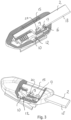
- Figure 1 refers a windscreen wiper device of the flat blade type built up of a wiper blade, in the longitudinal sides of which opposing longitudinal groove are formed, and of longitudinal strips ("flexors") made of spring band steel, which are fitted in said longitudinal grooves. Said strips form a flexible carrier element for the rubber wiper blade, as it were, which is thus biased in a curved position (the curvature in operative position being that of a windscreen to be wiped).
- the windscreen wiper device is furthermore built up of a connecting device 1 of plastic material for a rod-like extension 2 of a windscreen wiper arm.
- Said connecting device 1 comprises a first part 3 and a second part 4 acting as a joint part, wherein said rod-like extension 2 arm can be pivotally connected to said first part 3 about said pivot axis, with the interposition of said second part 4.
- Said first part 3 comprises a flat base 5 having inwardly extending legs 6 integral therewith engaging around longitudinal sides of the wiper blade, at the location of said grooves, as a result of which the first part 1 is firmly attached to the unit consisting of the wiper blade and the strips.
- Said first part 3 comprises two opposite side walls 7,8 extending in upright direction from said flat base 5. On said opposite side walls 7,8 are formed cylindrical protuberances 9,10 extending outwardly.
- said second part 4 comprises a channel 15 arranged to receive (in a linear movement) said rod-like extension 2 of said oscillating arm.
- One of said side walls 8 of said first part 3 comprises a protrusion 16 extending sidewards and inwards and arranged to engage into a first recess 17 having an open circumference and provided on a longitudinal exterior side 18 of said rod-like extension 19.
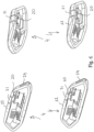
- the connecting device 1 is mounted or dismounting the connecting device 1 from the rod-like extension the second part 4 (and thus the free end of the rod-like extension 2 connected thereto), is pivoted relative to the first part 3, wherein reference is made to figures 1 , 2 middle and bottom.
- the protrusion or cam 16 is no longer in line with the first recess 17, so that the second part 4 and the first part 3 attached thereto can be released from the rod-like extension 2 (see service position seen in figure 2 middle and bottom).
- the protrusion or cam 16 becomes in line with the first recess 17, so that the second part 4 and the first part 3 attached thereto is retained onto the rod-like extension 2 (working position seen in figure 2 top).
- the mutually cooperating protrusion 16 and recess 17 act as second retention means in case first retention means, as explained below, would inadvertently fail.
- the rod-like extension 2 is also provided with a second recess 19 also having an open circumference and also provided on the same longitudinal exterior side 18 of said rod-like extension 2.
- said first and second recesses 17,19 have an open circumference and are spaced-apart in longitudinal direction.
- Said second recess 19 cooperates with a resilient tongue 20 on the second part 4 arranged to engage into a second recess 19, together acting as first retention means in this case.
- Said resilient tongue 20 is hingeable along a hinge axis between an inward position retaining said second part 4 (together with the first part 3 and the wiper blade attached thereon) onto said rod-like extension 2 and an outward position releasing second part 4 (together with the first part 3 and the wiper blade attached thereon) from said rod-like extension 2.
- Said resilient tongue is hingeable (i.e. activated and deactivated) from said inward position into said outward position by a push button 21.
- Said push button 21 forms a part of an outer wall 22 of said second part 4 and is located near a free end of said second part 4 facing towards said rod-like extension 2.
- said channel 15 comprises a first chamber 23 facing towards an entrance 24 of said channel 15, as well as a second chamber 25 facing away from said entrance 24.
- Said first chamber 23 is wider than said second chamber 25.
- Said first chamber 23 is arranged to receive a first part 26 of a free end of said rod-like extension 2, wherein said second chamber 25 is arranged to receive a second part 27 of said free end of said rod-like extension 2.
- the free end of said rod-like extension 2 has a cut-out 28 in order to form said two parts 26,27 therein, wherein the first part 26 is wider than the second part 27.
- the second part 27 forms a longitudinally extending finger, as if it were, to be accommodated in the correspondingly shaped second chamber 25 of the channel 15.
- the wider first part 26 is to be accommodated in the correspondingly shaped first chamber 23 of the channel 15.
- the first part 26 of the rod-like extension 2 comprises the recesses 17,19 cooperating with the protrusion 16 and the resilient tongue 20 of the connecting device 1.
- there two types of rod-like extension 2 to be accommodated in the chambers 23,25 of the channel 15 these types mutually differ in width A,B of said first and second parts 26,27 thereof.
- FIG 6 shows various bottom views of the second part 4 of the connecting device of figure 1 clearly showing how the resilient tongue 20 can be activated or deactivated with the help of the push button 21.
- the resilient tongue 20 By pushing in the push button 21 the resilient tongue 20 is removed from the recess 19, so that the wiper blade 2 may be released from the rod-like extension 2.
Landscapes
- Engineering & Computer Science (AREA)
- Mechanical Engineering (AREA)
- Pivots And Pivotal Connections (AREA)
Claims (19)
- Dispositif d'essuie-glace du type à balai plat comprenant un élément support allongé élastique, ainsi qu'un balai d'essuie-glace allongé constitué d'un matériau souple, qui peut être placé en butée avec un pare-brise à essuyer, lequel balai d'essuie-glace comprend au moins une rainure longitudinale, dans laquelle rainure est disposée au moins une bande longitudinale de l'élément support, lequel dispositif d'essuie-glace comprend un dispositif de raccordement (1) pour une extension en forme de tige (2) d'un bras oscillant, dans lequel ladite extension en forme de tige (2) peut être raccordée de manière pivotante audit dispositif de raccordement (1) autour d'un axe de pivot à proximité d'une extrémité libre de celui-ci,
dans lequel
ledit dispositif de raccordement (1) comprend un canal (15) conçu pour recevoir ladite extension en forme de tige (2), caractérisé en ce que ledit canal (15) comprend une première chambre (23) orientée vers une entrée (24) dudit canal (15), ainsi qu'une seconde chambre (25) orientée à l'opposé de ladite entrée (24), ladite première chambre (23) ayant une largeur supérieure à celle de la seconde chambre (25), dans lequel ladite première chambre (23) est conçue pour recevoir une première partie (26) de ladite extrémité libre de ladite extension en forme de tige (2), et dans lequel ladite seconde chambre (25) est conçue pour recevoir une seconde partie (27) de ladite extrémité libre de ladite extension en forme de tige (2), ladite première partie (26) de ladite extension en forme de tige (2) ayant une largeur supérieure à celle de ladite seconde partie (27) de ladite extension en forme de tige (2). - Dispositif d'essuie-glace selon la revendication 1, dans lequel ledit canal (15) est conçu pour recevoir deux types de ladite extension en forme de tige (2), lesdits types différant mutuellement par la largeur (A, B) desdites première et second parties (26, 27) de celle-ci.
- Dispositif d'essuie-glace selon la revendication 1 ou 2, dans lequel ledit dispositif de raccordement (1) comprend une saillie (16) s'étendant latéralement et vers l'intérieur, conçue pour s'engager dans un premier évidement (17) prévu sur un côté extérieur longitudinal (18) de ladite extension en forme de tige (2), dans lequel ledit dispositif de raccordement (1) comprend une languette élastique (20) conçue pour s'engager dans un second évidement (19) prévu sur ledit côté extérieur longitudinal (18) de ladite extension en forme de tige (2), et dans lequel ladite languette élastique (20) peut être articulée le long d'un axe d'articulation entre une position intérieure retenant ledit balai d'essuie-glace sur ladite extension en forme de tige (2) et une position extérieure libérant ledit balai d'essuie-glace de ladite extension en forme de tige (2).
- Dispositif d'essuie-glace selon la revendication 3, dans lequel ladite saillie (16) est dimensionnée de sorte que- dans une position de travail dudit balai d'essuie-glace pivoté par rapport à ladite extension en forme de tige (2), ladite saillie (16) s'engage dans ledit premier évidement (17) retenant ainsi ledit balai d'essuie-glace sur ladite extension en forme de tige (2) ;- dans une position d'entretien dudit balai d'essuie-glace pivoté par rapport à ladite extension en forme de tige (2), ladite saillie (16) se dégage de dudit premier évidement (17), libérant ainsi ledit balai d'essuie-glace de ladite extension en forme de tige (2).
- Dispositif d'essuie-glace selon la revendication 3 ou 4, dans lequel lesdits premier et second évidements (17, 19) ont une circonférence ouverte et sont espacés dans la direction longitudinale.
- Dispositif d'essuie-glace selon la revendication 3, 4 ou 5, dans lequel ladite languette élastique (20) peut être articulée de ladite position intérieure à ladite position extérieure par un bouton poussoir (21), dans lequel ledit bouton poussoir (21) fait partie d'une paroi extérieure (22) dudit dispositif de raccordement (1).
- Dispositif d'essuie-glace selon la revendication 6, dans lequel ledit bouton poussoir (21) est situé près d'une extrémité libre dudit dispositif de raccordement (1) orientée vers ladite extension en forme de tige (2).
- Dispositif d'essuie-glace selon l'une quelconque des revendications précédentes 3 à 7, dans lequel ledit canal (15) a une longueur et une largeur, et dans lequel un plan s'étendant dans une direction de la largeur dudit canal (15) et un plan s'étendant à travers ladite bande longitudinale le long d'une largeur de celle-ci à l'emplacement du dispositif de raccordement (1) forment un angle α, dans lequel de préférence 15°<α<60°.
- Dispositif d'essuie-glace selon l'une quelconque des revendications 3 à 8 précédentes, dans lequel ledit dispositif de raccordement (1) comprend une première partie (3) et une seconde partie (4), dans lequel ladite extension en forme de tige (2) dudit bras oscillant peut être raccordée de manière pivotante à ladite première partie (3) autour dudit axe de pivot, avec l'interposition de ladite seconde partie (4), dans lequel ladite seconde partie (4) comprend ledit canal (15), et dans lequel ladite première partie (3) est raccordée audit balai d'essuie-glace et ladite seconde partie (4) est raccordée de manière amovible à ladite première partie (3).
- Dispositif d'essuie-glace selon la revendication 9, dans lequel ladite première partie (3) et ladite seconde partie (4) sont pourvues de moyens de pivot coopérant mutuellement pour raccorder de manière pivotante ladite seconde partie (4) à ladite première partie (3).
- Dispositif d'essuie-glace selon la revendication 10, dans lequel ladite seconde partie (4) est raccordée à ladite première partie (3) par des saillies (9, 10) en prise de manière pivotante de ladite première partie (3), à l'emplacement de l'axe de pivot, dans des évidements (11, 12) prévus dans ladite seconde partie (4).
- Dispositif d'essuie-glace (1) selon la revendication 9, 10 ou 11, dans lequel ladite seconde partie (4) est raccordé de manière amovible à ladite première partie (3) par une opération d'emboîtement/clipsage.
- Dispositif d'essuie-glace selon l'une quelconque des revendications 9 à 12 précédentes, dans lequel ladite première partie (3) comprend une base plate (5) comportant des pattes (6) d'un seul tenant avec celle-ci et venant en prise autour des côtés longitudinaux du balai d'essuie-glace, à l'emplacement de ladite rainure.
- Dispositif d'essuie-glace selon la revendication 13, dans lequel ladite première partie (3) comprend deux parois latérales opposées (7, 8) s'étendant vers le haut à partir de ladite base (5), et dans lequel l'une desdites parois latérales (8) comprend ladite saillie (16) s'étendant latéralement et vers l'intérieur.
- Dispositif d'essuie-glace selon la revendication 14, dans lequel lesdites saillies (9, 10) en prise de manière pivotante de ladite première partie (3) sont disposées vers l'extérieur sur lesdites parois latérales opposées (7, 8), et dans lequel lesdits évidements (11, 12) sont disposés vers l'intérieur dans les parois opposées (13, 14) de ladite seconde partie (4).
- Dispositif d'essuie-glace selon la revendication 14 ou 15, dans lequel lesdites parois latérales (7, 8) de ladite première partie (3) sont entièrement situées à l'intérieur de ladite seconde partie (4) dans une position de travail dudit balai d'essuie-glace.
- Dispositif d'essuie-glace selon l'une quelconque des revendications 9 à 16 précédentes, dans lequel ladite première et ladite seconde partie (3, 4) sont chacune constituées en une partie de matériau plastique.
- Dispositif de raccordement (1) agencé pour être utilisé dans un dispositif d'essuie-glace selon l'une quelconque des revendications 1 à 17 précédentes, dans lequel ledit dispositif de raccordement (1) comprend un canal (15) agencé pour recevoir une extension en forme de tige (2) d'un bras oscillant, ledit canal (15) comprenant une première chambre (23) orientée vers une entrée (24) dudit canal (15), ainsi qu'une seconde chambre (25) orientée à l'opposé de ladite entrée (24), ladite première chambre (23) ayant une largeur supérieure à celle de ladite seconde chambre (25), dans lequel ledit dispositif de raccordement (1) comprend une saillie (16) s'étendant latéralement et vers l'intérieur, conçue pour s'engager dans un premier évidement (17) prévu sur un côté extérieur longitudinal (18) de ladite extension en forme de tige (2), dans lequel ledit dispositif de raccordement (1) comprend une languette élastique (20) conçue pour s'engager dans un second évidement (19) prévu sur ledit côté extérieur longitudinal (18) de ladite extension en forme de tige (2), et dans lequel ladite languette élastique (20) peut être articulée le long d'un axe d'articulation entre une position intérieure retenant ledit balai d'essuie-glace sur ladite extension en forme de tige (2) et une position extérieure libérant ledit balai d'essuie-glace de ladite extension en forme de tige (2).
- Bras oscillant avec une extension en forme de tige (2) agencé pour être utilisé dans un dispositif d'essuie-glace selon l'une quelconque des revendications 1 à 17 précédentes, dans lequel ladite extension en forme de tige (2) comprend une seconde partie (27) orientée vers une extrémité libre de celle-ci, ainsi qu'une première partie (26) orientée à l'opposé de ladite extrémité libre de celle-ci, et dans lequel ladite première partie (26) a une largeur supérieure à celle de ladite seconde partie (27) caractérisé en ce que ladite extension en forme de tige (2) comprend un premier évidement (17) prévu sur un côté extérieur longitudinal (18) de celle-ci et agencé pour être mis en prise avec une saillie (16) s'étendant latéralement et intérieurement dudit dispositif de raccordement (1), dans laquelle ladite extension en forme de tige (2) comprend un second évidement (19) prévu sur ledit côté extérieur longitudinal (18) de celle-ci et agencé pour être mis en prise avec une languette élastique (20) dudit dispositif de raccordement (1).
Applications Claiming Priority (1)
| Application Number | Priority Date | Filing Date | Title |
|---|---|---|---|
| PCT/EP2018/069931 WO2020020431A1 (fr) | 2018-07-23 | 2018-07-23 | Dispositif d'essuie-glace du type à balai plat |
Publications (2)
| Publication Number | Publication Date |
|---|---|
| EP3826889A1 EP3826889A1 (fr) | 2021-06-02 |
| EP3826889B1 true EP3826889B1 (fr) | 2023-09-06 |
Family
ID=63047326
Family Applications (1)
| Application Number | Title | Priority Date | Filing Date |
|---|---|---|---|
| EP18746871.5A Active EP3826889B1 (fr) | 2018-07-23 | 2018-07-23 | Dispositif d'essuie-glace du type à balai plat |
Country Status (4)
| Country | Link |
|---|---|
| US (1) | US11465592B2 (fr) |
| EP (1) | EP3826889B1 (fr) |
| CN (1) | CN112469605B (fr) |
| WO (1) | WO2020020431A1 (fr) |
Cited By (1)
| Publication number | Priority date | Publication date | Assignee | Title |
|---|---|---|---|---|
| FR3152138A1 (fr) * | 2024-01-19 | 2025-02-21 | Valeo Systemes D Essuyage | Adaptateur pour balai d’essuie-glace et dispositif d’essuyage |
Families Citing this family (6)
| Publication number | Priority date | Publication date | Assignee | Title |
|---|---|---|---|---|
| CN114245778A (zh) * | 2019-06-28 | 2022-03-25 | 特瑞克产品公司 | 用于擦拭器刮片组件的多个擦拭器刮片转接器 |
| US12415480B2 (en) * | 2020-04-24 | 2025-09-16 | Trico Belgium S.a. | Windscreen wiper device of the flat blade type |
| FR3137037B1 (fr) * | 2022-06-23 | 2024-11-15 | Valeo Systemes Dessuyage | Adaptateur pour balai d’essuie-glace et dispositif d’essuyage |
| FR3143494A1 (fr) * | 2022-12-14 | 2024-06-21 | Valeo Systèmes D’Essuyage | Adaptateur d’un système d’essuyage |
| FR3143495A1 (fr) * | 2022-12-14 | 2024-06-21 | Valeo Systèmes D’Essuyage | Adaptateur d’un système d’essuyage |
| FR3143497B1 (fr) * | 2022-12-14 | 2025-03-28 | Valeo Systemes Dessuyage | Adaptateur pour balai d’essuie-glace et dispositif d’essuyage |
Citations (2)
| Publication number | Priority date | Publication date | Assignee | Title |
|---|---|---|---|---|
| DE1047040B (de) * | 1957-07-06 | 1958-12-18 | Avog Elektro Und Feinmechanik | Vorrichtung zum Befestigen des Wischblattes von Scheibenwischern |
| DE1088375B (de) * | 1957-06-15 | 1960-09-01 | Bosch Gmbh Robert | Einrichtung zum Befestigen der Wischerschiene am Wischerarm von Scheibenwischern |
Family Cites Families (9)
| Publication number | Priority date | Publication date | Assignee | Title |
|---|---|---|---|---|
| GB1126593A (en) * | 1964-12-24 | 1968-09-05 | Anadd Holdings Ltd | Improvements in windscreen wipers |
| GB1126594A (en) * | 1964-12-24 | 1968-09-05 | Anadd Holdings Ltd | Improvements in windscreen wipers |
| ES2337318T3 (es) * | 1999-10-11 | 2010-04-22 | Federal-Mogul S.A. | Dispositivo limpiaparabrisas. |
| EP1568558A1 (fr) * | 2004-02-25 | 2005-08-31 | Federal-Mogul S.A. | Dispositif d'essuie-glace |
| DE102006057024A1 (de) * | 2006-12-04 | 2008-06-05 | Robert Bosch Gmbh | Wischblatt |
| BRPI0704580A2 (pt) * | 2007-06-22 | 2009-02-10 | Dyna Electromecanica | sistema de encaixe de componentes da palheta |
| KR101608373B1 (ko) * | 2014-06-27 | 2016-04-01 | 케이씨더블류 주식회사 | 와이퍼 블레이드 |
| WO2016119852A1 (fr) * | 2015-01-29 | 2016-08-04 | Federal-Mogul S.A. | Dispositif d'essuie-glace du type à balai plat |
| EP3452341B1 (fr) | 2016-05-02 | 2020-05-06 | Federal-Mogul S.a. | Véhicule doté d'au moins deux dispositifs d'essuie-glace du type à balai plat |
-
2018
- 2018-07-23 EP EP18746871.5A patent/EP3826889B1/fr active Active
- 2018-07-23 US US17/262,808 patent/US11465592B2/en active Active
- 2018-07-23 CN CN201880095870.8A patent/CN112469605B/zh active Active
- 2018-07-23 WO PCT/EP2018/069931 patent/WO2020020431A1/fr not_active Ceased
Patent Citations (2)
| Publication number | Priority date | Publication date | Assignee | Title |
|---|---|---|---|---|
| DE1088375B (de) * | 1957-06-15 | 1960-09-01 | Bosch Gmbh Robert | Einrichtung zum Befestigen der Wischerschiene am Wischerarm von Scheibenwischern |
| DE1047040B (de) * | 1957-07-06 | 1958-12-18 | Avog Elektro Und Feinmechanik | Vorrichtung zum Befestigen des Wischblattes von Scheibenwischern |
Cited By (2)
| Publication number | Priority date | Publication date | Assignee | Title |
|---|---|---|---|---|
| FR3152138A1 (fr) * | 2024-01-19 | 2025-02-21 | Valeo Systemes D Essuyage | Adaptateur pour balai d’essuie-glace et dispositif d’essuyage |
| WO2025153728A1 (fr) * | 2024-01-19 | 2025-07-24 | Valeo Systèmes d'Essuyage | Adaptateur pour balai d'essuie-glace et dispositif d'essuyage |
Also Published As
| Publication number | Publication date |
|---|---|
| US20210309184A1 (en) | 2021-10-07 |
| US11465592B2 (en) | 2022-10-11 |
| CN112469605A (zh) | 2021-03-09 |
| CN112469605B (zh) | 2024-08-09 |
| WO2020020431A1 (fr) | 2020-01-30 |
| EP3826889A1 (fr) | 2021-06-02 |
Similar Documents
| Publication | Publication Date | Title |
|---|---|---|
| US11465592B2 (en) | Windscreen wiper device of the flat blade type | |
| EP3844037B1 (fr) | Dispositif d'essuie-glace du type à lame plate | |
| EP3898348B1 (fr) | Dispositif d'essuie-glace de pare brise du type à lame plate | |
| WO2016119852A1 (fr) | Dispositif d'essuie-glace du type à balai plat | |
| EP3452341A1 (fr) | Véhicule doté d'au moins deux dispositifs d'essuie-glace du type à balai plat | |
| KR20170026354A (ko) | 차창용 와이퍼 장치 | |
| EP4126602B1 (fr) | Dispositif d'essuie-glace du type à lame plate | |
| EP4139173B1 (fr) | Dispositif de balai d'essuie-glace du type à lame plate | |
| US11878662B2 (en) | Windscreen wiper device of the flat blade type | |
| US12344199B2 (en) | Windscreen wiper device of the flat blade type | |
| EP4010229B1 (fr) | Dispositif d'essuie-glace du type à lame plate | |
| EP3962787B1 (fr) | Dispositif d'essuie-glace du type à lame plate | |
| US20220176913A1 (en) | A windscreen wiper device of the flat blade type | |
| WO2023217388A1 (fr) | Dispositif d'essuie-glace du type à lame plate | |
| EP4366988A1 (fr) | Dispositif d'essuie-glace du type à balais plats | |
| JP2008162590A (ja) | ブレードラバー |
Legal Events
| Date | Code | Title | Description |
|---|---|---|---|
| STAA | Information on the status of an ep patent application or granted ep patent |
Free format text: STATUS: UNKNOWN |
|
| STAA | Information on the status of an ep patent application or granted ep patent |
Free format text: STATUS: THE INTERNATIONAL PUBLICATION HAS BEEN MADE |
|
| PUAI | Public reference made under article 153(3) epc to a published international application that has entered the european phase |
Free format text: ORIGINAL CODE: 0009012 |
|
| STAA | Information on the status of an ep patent application or granted ep patent |
Free format text: STATUS: REQUEST FOR EXAMINATION WAS MADE |
|
| 17P | Request for examination filed |
Effective date: 20210204 |
|
| AK | Designated contracting states |
Kind code of ref document: A1 Designated state(s): AL AT BE BG CH CY CZ DE DK EE ES FI FR GB GR HR HU IE IS IT LI LT LU LV MC MK MT NL NO PL PT RO RS SE SI SK SM TR |
|
| DAV | Request for validation of the european patent (deleted) | ||
| DAX | Request for extension of the european patent (deleted) | ||
| STAA | Information on the status of an ep patent application or granted ep patent |
Free format text: STATUS: EXAMINATION IS IN PROGRESS |
|
| 17Q | First examination report despatched |
Effective date: 20220707 |
|
| GRAP | Despatch of communication of intention to grant a patent |
Free format text: ORIGINAL CODE: EPIDOSNIGR1 |
|
| STAA | Information on the status of an ep patent application or granted ep patent |
Free format text: STATUS: GRANT OF PATENT IS INTENDED |
|
| INTG | Intention to grant announced |
Effective date: 20230511 |
|
| GRAS | Grant fee paid |
Free format text: ORIGINAL CODE: EPIDOSNIGR3 |
|
| GRAA | (expected) grant |
Free format text: ORIGINAL CODE: 0009210 |
|
| STAA | Information on the status of an ep patent application or granted ep patent |
Free format text: STATUS: THE PATENT HAS BEEN GRANTED |
|
| AK | Designated contracting states |
Kind code of ref document: B1 Designated state(s): AL AT BE BG CH CY CZ DE DK EE ES FI FR GB GR HR HU IE IS IT LI LT LU LV MC MK MT NL NO PL PT RO RS SE SI SK SM TR |
|
| REG | Reference to a national code |
Ref country code: GB Ref legal event code: FG4D |
|
| REG | Reference to a national code |
Ref country code: CH Ref legal event code: EP |
|
| REG | Reference to a national code |
Ref country code: DE Ref legal event code: R096 Ref document number: 602018057009 Country of ref document: DE |
|
| REG | Reference to a national code |
Ref country code: IE Ref legal event code: FG4D |
|
| REG | Reference to a national code |
Ref country code: LT Ref legal event code: MG9D |
|
| REG | Reference to a national code |
Ref country code: NL Ref legal event code: MP Effective date: 20230906 |
|
| PG25 | Lapsed in a contracting state [announced via postgrant information from national office to epo] |
Ref country code: GR Free format text: LAPSE BECAUSE OF FAILURE TO SUBMIT A TRANSLATION OF THE DESCRIPTION OR TO PAY THE FEE WITHIN THE PRESCRIBED TIME-LIMIT Effective date: 20231207 |
|
| PG25 | Lapsed in a contracting state [announced via postgrant information from national office to epo] |
Ref country code: SE Free format text: LAPSE BECAUSE OF FAILURE TO SUBMIT A TRANSLATION OF THE DESCRIPTION OR TO PAY THE FEE WITHIN THE PRESCRIBED TIME-LIMIT Effective date: 20230906 Ref country code: RS Free format text: LAPSE BECAUSE OF FAILURE TO SUBMIT A TRANSLATION OF THE DESCRIPTION OR TO PAY THE FEE WITHIN THE PRESCRIBED TIME-LIMIT Effective date: 20230906 Ref country code: NO Free format text: LAPSE BECAUSE OF FAILURE TO SUBMIT A TRANSLATION OF THE DESCRIPTION OR TO PAY THE FEE WITHIN THE PRESCRIBED TIME-LIMIT Effective date: 20231206 Ref country code: LV Free format text: LAPSE BECAUSE OF FAILURE TO SUBMIT A TRANSLATION OF THE DESCRIPTION OR TO PAY THE FEE WITHIN THE PRESCRIBED TIME-LIMIT Effective date: 20230906 Ref country code: LT Free format text: LAPSE BECAUSE OF FAILURE TO SUBMIT A TRANSLATION OF THE DESCRIPTION OR TO PAY THE FEE WITHIN THE PRESCRIBED TIME-LIMIT Effective date: 20230906 Ref country code: HR Free format text: LAPSE BECAUSE OF FAILURE TO SUBMIT A TRANSLATION OF THE DESCRIPTION OR TO PAY THE FEE WITHIN THE PRESCRIBED TIME-LIMIT Effective date: 20230906 Ref country code: GR Free format text: LAPSE BECAUSE OF FAILURE TO SUBMIT A TRANSLATION OF THE DESCRIPTION OR TO PAY THE FEE WITHIN THE PRESCRIBED TIME-LIMIT Effective date: 20231207 Ref country code: FI Free format text: LAPSE BECAUSE OF FAILURE TO SUBMIT A TRANSLATION OF THE DESCRIPTION OR TO PAY THE FEE WITHIN THE PRESCRIBED TIME-LIMIT Effective date: 20230906 |
|
| REG | Reference to a national code |
Ref country code: AT Ref legal event code: MK05 Ref document number: 1608151 Country of ref document: AT Kind code of ref document: T Effective date: 20230906 |
|
| PG25 | Lapsed in a contracting state [announced via postgrant information from national office to epo] |
Ref country code: NL Free format text: LAPSE BECAUSE OF FAILURE TO SUBMIT A TRANSLATION OF THE DESCRIPTION OR TO PAY THE FEE WITHIN THE PRESCRIBED TIME-LIMIT Effective date: 20230906 |
|
| PG25 | Lapsed in a contracting state [announced via postgrant information from national office to epo] |
Ref country code: IS Free format text: LAPSE BECAUSE OF FAILURE TO SUBMIT A TRANSLATION OF THE DESCRIPTION OR TO PAY THE FEE WITHIN THE PRESCRIBED TIME-LIMIT Effective date: 20240106 |
|
| PG25 | Lapsed in a contracting state [announced via postgrant information from national office to epo] |
Ref country code: AT Free format text: LAPSE BECAUSE OF FAILURE TO SUBMIT A TRANSLATION OF THE DESCRIPTION OR TO PAY THE FEE WITHIN THE PRESCRIBED TIME-LIMIT Effective date: 20230906 |
|
| PG25 | Lapsed in a contracting state [announced via postgrant information from national office to epo] |
Ref country code: ES Free format text: LAPSE BECAUSE OF FAILURE TO SUBMIT A TRANSLATION OF THE DESCRIPTION OR TO PAY THE FEE WITHIN THE PRESCRIBED TIME-LIMIT Effective date: 20230906 |
|
| PG25 | Lapsed in a contracting state [announced via postgrant information from national office to epo] |
Ref country code: SM Free format text: LAPSE BECAUSE OF FAILURE TO SUBMIT A TRANSLATION OF THE DESCRIPTION OR TO PAY THE FEE WITHIN THE PRESCRIBED TIME-LIMIT Effective date: 20230906 Ref country code: RO Free format text: LAPSE BECAUSE OF FAILURE TO SUBMIT A TRANSLATION OF THE DESCRIPTION OR TO PAY THE FEE WITHIN THE PRESCRIBED TIME-LIMIT Effective date: 20230906 Ref country code: IS Free format text: LAPSE BECAUSE OF FAILURE TO SUBMIT A TRANSLATION OF THE DESCRIPTION OR TO PAY THE FEE WITHIN THE PRESCRIBED TIME-LIMIT Effective date: 20240106 Ref country code: ES Free format text: LAPSE BECAUSE OF FAILURE TO SUBMIT A TRANSLATION OF THE DESCRIPTION OR TO PAY THE FEE WITHIN THE PRESCRIBED TIME-LIMIT Effective date: 20230906 Ref country code: EE Free format text: LAPSE BECAUSE OF FAILURE TO SUBMIT A TRANSLATION OF THE DESCRIPTION OR TO PAY THE FEE WITHIN THE PRESCRIBED TIME-LIMIT Effective date: 20230906 Ref country code: CZ Free format text: LAPSE BECAUSE OF FAILURE TO SUBMIT A TRANSLATION OF THE DESCRIPTION OR TO PAY THE FEE WITHIN THE PRESCRIBED TIME-LIMIT Effective date: 20230906 Ref country code: AT Free format text: LAPSE BECAUSE OF FAILURE TO SUBMIT A TRANSLATION OF THE DESCRIPTION OR TO PAY THE FEE WITHIN THE PRESCRIBED TIME-LIMIT Effective date: 20230906 Ref country code: SK Free format text: LAPSE BECAUSE OF FAILURE TO SUBMIT A TRANSLATION OF THE DESCRIPTION OR TO PAY THE FEE WITHIN THE PRESCRIBED TIME-LIMIT Effective date: 20230906 Ref country code: PT Free format text: LAPSE BECAUSE OF FAILURE TO SUBMIT A TRANSLATION OF THE DESCRIPTION OR TO PAY THE FEE WITHIN THE PRESCRIBED TIME-LIMIT Effective date: 20240108 |
|
| PG25 | Lapsed in a contracting state [announced via postgrant information from national office to epo] |
Ref country code: PL Free format text: LAPSE BECAUSE OF FAILURE TO SUBMIT A TRANSLATION OF THE DESCRIPTION OR TO PAY THE FEE WITHIN THE PRESCRIBED TIME-LIMIT Effective date: 20230906 Ref country code: IT Free format text: LAPSE BECAUSE OF FAILURE TO SUBMIT A TRANSLATION OF THE DESCRIPTION OR TO PAY THE FEE WITHIN THE PRESCRIBED TIME-LIMIT Effective date: 20230906 |
|
| REG | Reference to a national code |
Ref country code: DE Ref legal event code: R097 Ref document number: 602018057009 Country of ref document: DE |
|
| PG25 | Lapsed in a contracting state [announced via postgrant information from national office to epo] |
Ref country code: DK Free format text: LAPSE BECAUSE OF FAILURE TO SUBMIT A TRANSLATION OF THE DESCRIPTION OR TO PAY THE FEE WITHIN THE PRESCRIBED TIME-LIMIT Effective date: 20230906 |
|
| PLBE | No opposition filed within time limit |
Free format text: ORIGINAL CODE: 0009261 |
|
| STAA | Information on the status of an ep patent application or granted ep patent |
Free format text: STATUS: NO OPPOSITION FILED WITHIN TIME LIMIT |
|
| PG25 | Lapsed in a contracting state [announced via postgrant information from national office to epo] |
Ref country code: DK Free format text: LAPSE BECAUSE OF FAILURE TO SUBMIT A TRANSLATION OF THE DESCRIPTION OR TO PAY THE FEE WITHIN THE PRESCRIBED TIME-LIMIT Effective date: 20230906 Ref country code: SI Free format text: LAPSE BECAUSE OF FAILURE TO SUBMIT A TRANSLATION OF THE DESCRIPTION OR TO PAY THE FEE WITHIN THE PRESCRIBED TIME-LIMIT Effective date: 20230906 |
|
| 26N | No opposition filed |
Effective date: 20240607 |
|
| PG25 | Lapsed in a contracting state [announced via postgrant information from national office to epo] |
Ref country code: BG Free format text: LAPSE BECAUSE OF FAILURE TO SUBMIT A TRANSLATION OF THE DESCRIPTION OR TO PAY THE FEE WITHIN THE PRESCRIBED TIME-LIMIT Effective date: 20230906 |
|
| PG25 | Lapsed in a contracting state [announced via postgrant information from national office to epo] |
Ref country code: BG Free format text: LAPSE BECAUSE OF FAILURE TO SUBMIT A TRANSLATION OF THE DESCRIPTION OR TO PAY THE FEE WITHIN THE PRESCRIBED TIME-LIMIT Effective date: 20230906 |
|
| PG25 | Lapsed in a contracting state [announced via postgrant information from national office to epo] |
Ref country code: MC Free format text: LAPSE BECAUSE OF FAILURE TO SUBMIT A TRANSLATION OF THE DESCRIPTION OR TO PAY THE FEE WITHIN THE PRESCRIBED TIME-LIMIT Effective date: 20230906 |
|
| REG | Reference to a national code |
Ref country code: CH Ref legal event code: PL |
|
| PG25 | Lapsed in a contracting state [announced via postgrant information from national office to epo] |
Ref country code: LU Free format text: LAPSE BECAUSE OF NON-PAYMENT OF DUE FEES Effective date: 20240723 |
|
| GBPC | Gb: european patent ceased through non-payment of renewal fee |
Effective date: 20240723 |
|
| PG25 | Lapsed in a contracting state [announced via postgrant information from national office to epo] |
Ref country code: LU Free format text: LAPSE BECAUSE OF NON-PAYMENT OF DUE FEES Effective date: 20240723 |
|
| PG25 | Lapsed in a contracting state [announced via postgrant information from national office to epo] |
Ref country code: CH Free format text: LAPSE BECAUSE OF NON-PAYMENT OF DUE FEES Effective date: 20240731 |
|
| PG25 | Lapsed in a contracting state [announced via postgrant information from national office to epo] |
Ref country code: GB Free format text: LAPSE BECAUSE OF NON-PAYMENT OF DUE FEES Effective date: 20240723 |
|
| PG25 | Lapsed in a contracting state [announced via postgrant information from national office to epo] |
Ref country code: IE Free format text: LAPSE BECAUSE OF NON-PAYMENT OF DUE FEES Effective date: 20240723 |
|
| PGFP | Annual fee paid to national office [announced via postgrant information from national office to epo] |
Ref country code: DE Payment date: 20250729 Year of fee payment: 8 |
|
| PGFP | Annual fee paid to national office [announced via postgrant information from national office to epo] |
Ref country code: BE Payment date: 20250728 Year of fee payment: 8 |
|
| PGFP | Annual fee paid to national office [announced via postgrant information from national office to epo] |
Ref country code: FR Payment date: 20250725 Year of fee payment: 8 |
|
| PG25 | Lapsed in a contracting state [announced via postgrant information from national office to epo] |
Ref country code: CY Free format text: LAPSE BECAUSE OF FAILURE TO SUBMIT A TRANSLATION OF THE DESCRIPTION OR TO PAY THE FEE WITHIN THE PRESCRIBED TIME-LIMIT; INVALID AB INITIO Effective date: 20180723 |
|
| PG25 | Lapsed in a contracting state [announced via postgrant information from national office to epo] |
Ref country code: HU Free format text: LAPSE BECAUSE OF FAILURE TO SUBMIT A TRANSLATION OF THE DESCRIPTION OR TO PAY THE FEE WITHIN THE PRESCRIBED TIME-LIMIT; INVALID AB INITIO Effective date: 20180723 |