EP4010229B1 - Dispositif d'essuie-glace du type à lame plate - Google Patents
Dispositif d'essuie-glace du type à lame plate Download PDFInfo
- Publication number
- EP4010229B1 EP4010229B1 EP19752469.7A EP19752469A EP4010229B1 EP 4010229 B1 EP4010229 B1 EP 4010229B1 EP 19752469 A EP19752469 A EP 19752469A EP 4010229 B1 EP4010229 B1 EP 4010229B1
- Authority
- EP
- European Patent Office
- Prior art keywords
- extension
- rod
- windscreen wiper
- wiper device
- channel
- Prior art date
- Legal status (The legal status is an assumption and is not a legal conclusion. Google has not performed a legal analysis and makes no representation as to the accuracy of the status listed.)
- Active
Links
Images


Classifications
-
- B—PERFORMING OPERATIONS; TRANSPORTING
- B60—VEHICLES IN GENERAL
- B60S—SERVICING, CLEANING, REPAIRING, SUPPORTING, LIFTING, OR MANOEUVRING OF VEHICLES, NOT OTHERWISE PROVIDED FOR
- B60S1/00—Cleaning of vehicles
- B60S1/02—Cleaning windscreens, windows or optical devices
- B60S1/04—Wipers or the like, e.g. scrapers
- B60S1/32—Wipers or the like, e.g. scrapers characterised by constructional features of wiper blade arms or blades
- B60S1/38—Wiper blades
- B60S1/3848—Flat-type wiper blade, i.e. without harness
- B60S1/3849—Connectors therefor; Connection to wiper arm; Attached to blade
- B60S1/3863—Connectors having a spoiler
-
- B—PERFORMING OPERATIONS; TRANSPORTING
- B60—VEHICLES IN GENERAL
- B60S—SERVICING, CLEANING, REPAIRING, SUPPORTING, LIFTING, OR MANOEUVRING OF VEHICLES, NOT OTHERWISE PROVIDED FOR
- B60S1/00—Cleaning of vehicles
- B60S1/02—Cleaning windscreens, windows or optical devices
- B60S1/04—Wipers or the like, e.g. scrapers
- B60S1/32—Wipers or the like, e.g. scrapers characterised by constructional features of wiper blade arms or blades
- B60S1/40—Connections between blades and arms
- B60S1/4083—Connections between blades and arms for arms provided with a flat end
- B60S1/4087—Connections between blades and arms for arms provided with a flat end the end being provided with protrusions or holes
-
- B—PERFORMING OPERATIONS; TRANSPORTING
- B60—VEHICLES IN GENERAL
- B60S—SERVICING, CLEANING, REPAIRING, SUPPORTING, LIFTING, OR MANOEUVRING OF VEHICLES, NOT OTHERWISE PROVIDED FOR
- B60S1/00—Cleaning of vehicles
- B60S1/02—Cleaning windscreens, windows or optical devices
- B60S1/04—Wipers or the like, e.g. scrapers
- B60S1/32—Wipers or the like, e.g. scrapers characterised by constructional features of wiper blade arms or blades
- B60S1/38—Wiper blades
- B60S1/3848—Flat-type wiper blade, i.e. without harness
- B60S1/3849—Connectors therefor; Connection to wiper arm; Attached to blade
-
- B—PERFORMING OPERATIONS; TRANSPORTING
- B60—VEHICLES IN GENERAL
- B60S—SERVICING, CLEANING, REPAIRING, SUPPORTING, LIFTING, OR MANOEUVRING OF VEHICLES, NOT OTHERWISE PROVIDED FOR
- B60S1/00—Cleaning of vehicles
- B60S1/02—Cleaning windscreens, windows or optical devices
- B60S1/04—Wipers or the like, e.g. scrapers
- B60S1/32—Wipers or the like, e.g. scrapers characterised by constructional features of wiper blade arms or blades
- B60S1/38—Wiper blades
- B60S1/3848—Flat-type wiper blade, i.e. without harness
- B60S1/3849—Connectors therefor; Connection to wiper arm; Attached to blade
- B60S1/3851—Mounting of connector to blade assembly
- B60S1/3855—Mounting of connector to blade assembly by welding, gluing or the like
-
- B—PERFORMING OPERATIONS; TRANSPORTING
- B60—VEHICLES IN GENERAL
- B60S—SERVICING, CLEANING, REPAIRING, SUPPORTING, LIFTING, OR MANOEUVRING OF VEHICLES, NOT OTHERWISE PROVIDED FOR
- B60S1/00—Cleaning of vehicles
- B60S1/02—Cleaning windscreens, windows or optical devices
- B60S1/04—Wipers or the like, e.g. scrapers
- B60S1/32—Wipers or the like, e.g. scrapers characterised by constructional features of wiper blade arms or blades
- B60S1/40—Connections between blades and arms
- B60S2001/409—Connections between blades and arms characterised by the arm or connecting part mounted on the arm presenting a shaped opening for bearing the pivot axis
Definitions
- the present invention relates to a windscreen wiper device of the flat blade type comprising an elastic, elongated carrier element, as well as an elongated wiper blade of a flexible material, which can be placed in abutment with a windscreen to be wiped, which wiper blade includes at least one longitudinal slit, in which slit at least one longitudinal strip of the carrier element is disposed, which windscreen wiper device comprises a connecting device for a rod-like extension of an oscillating arm, wherein the rod-like extension can be pivotally connected to said connecting device about a pivot axis near one end thereof, wherein said connecting device comprises a first part and a second part, wherein said rod-like extension of said oscillating arm can be pivotally connected to said first part about said pivot axis, with the interposition of said second part, wherein said first part is connected to said wiper blade and said second part is detachably connected to said first part.
- Said longitudinal strip is also called a "flexor”
- said connecting device is also indicated
- said wiper blade comprises a spoiler at a side thereof facing away from the windscreen to be wiped.
- the spoiler is also called an "air deflector” and is preferably made in one piece with said wiper blade through extrusion.
- Said longitudinal slit is preferably a central longitudinal slit accommodating said longitudinal strip.
- Said connecting device is preferably fixedly connected to the longitudinal strip(s) particularly through a welding, brazing ("soldering"), gluing or clamping operation or with the help of a pin inserted through said connecting device and said longitudinal strip(s).
- said connecting device is clamped onto the flexible material of the wiper blade, particularly in case the latter is equipped with a central longitudinal slit for the carrier element.
- said oscillating arm is connected to a mounting head mounted on a drive shaft, wherein said oscillating arm at one end thereof is pivotally connected to the mounting head by means of a pivot pin and at another end thereof is connected to said wiper blade placed in abutment with said windscreen to be wiped.
- the shaft rotates alternately in a clockwise and in a counterclockwise sense carrying the mounting head into rotation also, which in turn draws the oscillating arm into rotation and by means of said connecting device moves the wiper blade.
- Said oscillating arm can thus oscillate to-and-from between first and second reversal positions.
- a windscreen wiper device is generally known.
- This prior art windscreen wiper device is designed as a so-called “flat blade” or “yokeless blade”, wherein no use is made of several yokes pivotally connected to each other, but wherein the wiper blade is biased by the carrier element, as a result of which it exhibits a specific curvature.
- Tests of the known windscreen wiper device has revealed that, particularly when use is made of an inclined upper surface of the second part of the connecting device in order to achieve an air deflecting effect, a front side and a back side of this second part have mutually different geometries, leading to mutually different stresses on said front side and said back side, particularly in the event that said second part is mounted onto said first part of this connecting device.
- a windscreen wiper device of the type referred to in the introduction is characterized according to the invention in that said second part comprises a channel arranged to receive said free end of said rod-like extension, wherein said second part has a U-shaped cross-section having an inclined base and two legs extending downwardly from said base, and wherein said second part comprises reinforcement means to arrange that bending locations of said legs upon snapping said second part onto said first part lie in the same horizontal plane.
- Said inclined base or upper surface of the second part of this connecting device functions in use as an air deflector or spoiler in order to reduce the pressure distribution on a wiping lip of the wiper blade.
- Said reinforcement means ensure that bending locations of said legs, particularly upon snapping said second part onto said first part, lie in the same horizontal plane, so that these bending locations mutually have the same height. Hence, stresses exerted on the legs, particularly at these bending locations, for example upon snapping the second part onto the first part, are more or less the same. This results in less damage, wear and aging.
- said inclined base in use is located upstream in an upward movement of the oscillating arm.
- said legs have the same height and the same thickness below said horizontal plane.
- said reinforcement means comprise a transverse rib locally reinforcing one of said legs.
- said transverse rib defines another channel in the second part parallel to said channel arranged to receive said free end of said rod-like extension.
- said channel includes a first chamber facing towards an entrance of said channel, as well as a second chamber facing away from said entrance, said first chamber having a larger width than said second chamber, wherein said first chamber is arranged to receive a first part of said free end of said rod-like extension, and wherein said second chamber is arranged to receive a second part of said free end of said rod-like extension, said first part of said rod-like extension having a larger width than said second part of said rod-like extension.
- the free end of said rod-like extension has a cut-out in order to form the two parts therein, wherein the first part is wider than the second part.
- the second part forms a longitudinally extending finger to be accommodated in the correspondingly shaped second chamber of the channel.
- the wider first part is to be accommodated in the correspondingly shaped first chamber of the channel. Due to the cut-out there is a larger guiding surface in the connecting device to guide the rod-like extension inside said channel in a reliable yet controlled manner.
- said first and second chambers of the channel have a closed circumference to enhance retention of the rod-like extension therein.
- said connecting device comprises a sidewardly and inwardly extending protrusion arranged to engage into a first recess provided on a longitudinal exterior side of said rod-like extension, wherein said connecting device comprises a resilient tongue arranged to engage into a second recess provided on said longitudinal exterior side of said rod-like extension, and wherein said resilient tongue is hingeable along a hinge axis between an inward position retaining said wiper blade onto said rod-like extension and an outward position releasing said wiper blade from said rod-like extension.
- said channel has a closed circumference. More in particular, said channel is formed by a hole having a closed circumference.
- first and second retention means are used independently from one another, i.e. the first retention means can be used without the second retention means and the second retention means can be used without the first retention means.
- said first and second recesses have an open circumference and are spaced-apart in longitudinal direction.
- said channel has a length and a width, wherein a plane extending in a direction of the width of said channel and a plane extending through said longitudinal strip along a width thereof at the location of the connecting device enclose an angle ⁇ , wherein preferably 15 0 ⁇ 60 0 .
- a centre line of the cross-sectional plane of said channel encloses the angle ⁇ with a symmetry axis of said longitudinal groove. Because of the angle ⁇ less pressure by the oscillating arm on the wiper blade is necessary to maintain high velocity wiping performances.
- said oscillating arm is equipped with said rod-like extension preferably having a rectangular cross-section, wherein said extension is to be inserted in the channel of the connecting device, and wherein said extension has a twisted orientation relative to the oscillating arm preferably having a U-shaped cross-section.
- a twisted arm extension has proven to considerably improve an air flow, to considerably reduce a height of the windscreen wiper device, whereas its design is attractive from a commercial perspective.
- Said channel preferably having a rectangular cross-section as well, has a possible twisted orientation corresponding to the twisted orientation of the arm extension in order to accommodate said arm extension during use.
- a bottom of said channel does not extend parallel to a windscreen to be wiped (when the oscillating arm in one of said reversal positions is in a central region of the windscreen to be wiped and disregarding any small curvature thereof in that region), but said bottom and said windscreen to be wiped enclose said angle ⁇ in that region.
- the present invention is not restricted to the use of only one longitudinal strip forming the elastic carrier element that is particularly located in a central longitudinal slit or groove of the wiper blade.
- said carrier element may also comprise two longitudinal strips, wherein said strips are disposed in opposite longitudinal slits/grooves of the wiper blade. Said slit(s)/groove(s) may be closed at one outer end.
- said first part and said second part are provided with mutually cooperating pivot means for pivotally connecting said second part to said first part.
- said second part is connected to said first part by pivotally engaging protuberances of said first part, at the location of said pivot axis, in recesses provided in said second part. Said protuberances are particularly mutually spaced far apart, so as to reduce angular play and to reduce wear.
- said first part comprises a flat base having legs integral therewith engaging around longitudinal sides of the wiper blade, at the location of said slit.
- said first part comprises two opposite side walls extending in upright direction from said flat base, said side walls of said first part being entirely located inside said second part in a working position of said wiper blade.
- said first and said second parts are each made in one piece of plastic material.
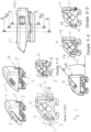
- Figure 1 refers a windscreen wiper device of the flat blade type in accordance with the invention, built up of a wiper blade, in the longitudinal sides of which opposing longitudinal slits are formed, and of longitudinal strips ("flexors") made of spring band steel, which are fitted in said longitudinal slits. Said strips form a flexible carrier element for the rubber wiper blade, as it were, which is thus biased in a curved position (the curvature in operative position being that of a windscreen to be wiped).
- the windscreen wiper device is furthermore built up of a connecting device 1 of plastic material for a rod-like extension 2 of a windscreen wiper arm.
- Said connecting device 1 comprises a first part 3 and a second part 4 acting as a joint part, wherein said rod-like extension 2 arm can be pivotally connected to said first part 3 about said pivot axis, with the interposition of said second part 4.
- said first part 3 comprises a flat base 5 having inwardly extending legs 6 integral therewith engaging around longitudinal sides of the wiper blade, at the location of said grooves, as a result of which the first part 1 is firmly attached to the unit consisting of the wiper blade and the strips.
- Said first part 3 comprises two opposite side walls 7,8 extending in upright direction from said flat base 5. On said opposite side walls 7,8 are formed cylindrical protuberances 9,10 extending outwardly.
- said second part 4 comprises a channel 15 arranged to receive (in a linear movement) said rod-like extension 2 of said oscillating arm.
- One of said side walls 8 of said first part 3 comprises a protrusion 16 extending sidewards and inwards and arranged to engage into a first recess 17 having an open circumference and provided on a longitudinal exterior side 18 of said rod-like extension 2.
- the second part 4 (and thus the free end of the rod-like extension 2 connected thereto), is pivoted relative to the first part 3, wherein reference is made to figure 1 .
- the protrusion or cam 16 is no longer in line with the first recess 17, so that the second part 4 and the first part 3 attached thereto can be released from the rod-like extension 2 (service position).
- the protrusion or cam 16 becomes in line with the first recess 17, so that the second part 4 and the first part 3 attached thereto is retained onto the rod-like extension 2 (working position).
- the mutually cooperating protrusion 16 and recess 17 act as second retention means in case first retention means, as explained below, would inadvertently fail.
- the rod-like extension 2 is also provided with a second recess 19 also having an open circumference and also provided on the same longitudinal exterior side 18 of said rod-like extension 2.
- said first and second recesses 17,19 have an open circumference and are spaced-apart in longitudinal direction.
- Said second recess 19 cooperates with a resilient tongue 20 on the second part 4 arranged to engage into a second recess 19, together acting as first retention means in this case.
- Said resilient tongue 20 is hingeable along a hinge axis between an inward position retaining said second part 4 (together with the first part 3 and the wiper blade attached thereon) onto said rod-like extension 2 and an outward position releasing second part 4 (together with the first part 3 and the wiper blade attached thereon) from said rod-like extension 2.
- Said resilient tongue is hingeable (i.e. activated and deactivated) from said inward position into said outward position by a push button 21.
- Said push button 21 forms a part of an outer wall 22 of said second part 4 and is located near a free end of said second part 4 facing towards said rod-like extension 2.
- said second part 4 has a U-shaped cross-section with an inclined base 23 and legs or opposite sidewalls 13,14.
- a transverse rib 24 is provided for interconnecting the downstream sidewall or leg 14 with the body of the second part 4.
- Said transverse rib 24 acts as reinforcement means ensuring that bending locations 25 of said legs 13,14, particularly upon snapping said second part 4 onto said first part 3, lie in the same horizontal plane A.
- these bending locations 25 mutually have the same height.
- stresses exerted on the legs 13,14, particularly at these bending locations 25, for example upon snapping the second part 4 onto the first part 3 are more or less the same. This results in less damage, wear and aging.
- the legs or sidewalls 13,14 have the same height and the same thickness below the plane A.
- Said transverse rib 24 defines another internal channel 26 in the second part 4 parallel to said channel 15 arranged to receive said free end of said rod-like extension 2. This is all in contrast to the connecting device of figure 2 , wherein the second parts has, seen in cross-section, bending locations 27 mutually differing in height and thus resulting in mutually differing stresses on the sidewalls/legs 13,14 during wiping, mounting etcetera.
Landscapes
- Engineering & Computer Science (AREA)
- Mechanical Engineering (AREA)
- Pivots And Pivotal Connections (AREA)
Claims (12)
- Dispositif d'essuie-glace de pare-brise du type à balai plat comprenant un élément porteur élastique allongé, ainsi qu'un balai d'essuie-glace allongé en matériau flexible, qui peut être placé en butée avec un pare-brise à essuyer, lequel balai d'essuie-glace comporte au moins une fente longitudinale, dans laquelle fente au moins une bande longitudinale de l'élément porteur est disposée, lequel dispositif d'essuie-glace de pare-brise comprend un dispositif de liaison (1) pour une extension en forme de tige (2) d'un bras oscillant, dans lequel ladite extension en forme de tige (2) peut être reliée de manière pivotante audit dispositif de liaison (1) autour d'un axe de pivotement à proximité d'une extrémité libre de celle-ci, dans lequel ledit dispositif de liaison (1) comprend une première partie (3) et une seconde partie (4), dans lequel ladite extension en forme de tige (2) dudit bras oscillant peut être reliée de manière pivotante à ladite première partie (3) autour dudit axe de pivotement, avec l'interposition de ladite seconde partie (4), dans lequel ladite première partie (3) est reliée audit balai d'essuie-glace et ladite seconde partie (4) est encliquetée de manière amovible sur ladite première partie (3), dans lequel ladite seconde partie (4) comprend un canal (15) agencé pour recevoir ladite extrémité libre de ladite extension en forme de tige (2), et dans lequel ladite seconde partie (4) a une section transversale à profil en U ayant une base inclinée (23) et deux pattes (13, 14) s'étendant vers le bas à partir de ladite base (23), caractérisé en ce que ladite seconde partie (4) comprend des moyens de renforcement pour faire en sorte que les points de courbure (25) desdites pattes (13, 14) lors de l'encliquetage de ladite seconde partie (4) sur ladite première partie (3) se situent dans le même plan horizontal (A), dans lequel lesdites pattes (13, 14) ont la même hauteur et la même épaisseur sous ledit plan horizontal (A).
- Dispositif d'essuie-glace de pare-brise selon la revendication 1, dans lequel lesdits moyens de renforcement comprennent une nervure traversante (24) renforçant localement l'une desdites pattes (13, 14).
- Dispositif d'essuie-glace de pare-brise selon la revendication 2, dans lequel ladite nervure traversante (24) définit un autre canal (26) dans la seconde partie (4) parallèle audit canal (15) agencé pour recevoir ladite extrémité libre de ladite extension en forme de tige (2).
- Dispositif d'essuie-glace de pare-brise selon l'une quelconque des revendications précédentes 1 à 3, dans lequel ladite base inclinée (23) en utilisation est localisée en amont dans un mouvement vers le haut du bras oscillant.
- Dispositif d'essuie-glace de pare-brise selon l'une quelconque des revendications précédentes 1 à 4, dans lequel ledit canal (15) comporte une première chambre (23) faisant face à une entrée (24) dudit canal (15), ainsi qu'une seconde chambre (25) faisant face à l'opposé de ladite entrée (24), ladite première chambre (23) ayant une largeur plus importante que ladite seconde chambre (25), dans lequel ladite première chambre (23) est agencée pour recevoir une première partie (26) de ladite extrémité libre de ladite extension en forme de tige (2), et dans lequel ladite seconde chambre (25) est agencée pour recevoir une seconde partie (27) de ladite extrémité libre de ladite extension en forme de tige (2), ladite première partie (26) de ladite extension en forme de tige (2) ayant une largeur plus importante que ladite seconde partie (27) de ladite extension en forme de tige (2).
- Dispositif d'essuie-glace de pare-brise selon l'une quelconque des revendications précédentes 1 à 5, dans lequel ledit dispositif de liaison (1) comprend une saillie (16) s'étendant latéralement et vers l'intérieur, agencée pour venir en prise dans un premier renfoncement (17) pourvu sur un côté extérieur longitudinal (18) de ladite extension en forme de tige (2), dans lequel ledit dispositif de liaison (1) comprend une languette souple (20) agencée pour venir en prise dans un second renfoncement (19) pourvu sur ledit côté extérieur longitudinal (18) de ladite extension en forme de tige (2), et dans lequel ladite languette souple (20) peut être articulée le long d'un axe d'articulation entre une position vers l'intérieur retenant ledit balai d'essuie-glace sur ladite extension en forme de tige (2) et une position vers l'extérieur libérant ledit balai d'essuie-glace de ladite extension en forme de tige (2).
- Dispositif d'essuie-glace de pare-brise selon l'une quelconque des revendications précédentes 1 à 6, dans lequel ledit premier canal (15) a une longueur et une largeur, et dans lequel un plan s'étendant dans une direction de la largeur dudit canal (15) et un plan s'étendant à travers ladite bande longitudinale le long d'une largeur de celle-ci à la localisation du dispositif de liaison (1) forment un angle α, dans lequel de préférence 15°< α <60°.
- Dispositif d'essuie-glace de pare-brise selon l'une quelconque des revendications précédentes 1 à 7, dans lequel ladite première partie (3) et ladite seconde partie (4) sont pourvues de moyens de pivotement coopérant mutuellement pour relier de manière pivotante ladite seconde partie (4) à ladite première partie (3).
- Dispositif d'essuie-glace de pare-brise selon la revendication 8, dans lequel ladite seconde partie (4) est reliée à ladite première partie (3) par la mise en prise pivotante de protubérances (9, 10) de ladite première partie (3), à la localisation dudit axe de pivotement, dans des renfoncements (11, 12) pourvus dans ladite seconde partie (4).
- Dispositif d'essuie-glace de pare-brise selon l'une quelconque des revendications précédentes 1 à 9, dans lequel ladite première partie (3) comprend une base plate (5) ayant des pattes (6) solidaires de celle-ci qui viennent en prise autour de côtés longitudinaux du balai d'essuie-glace, à la localisation de ladite fente.
- Dispositif d'essuie-glace de pare-brise selon la revendication 10, dans lequel ladite première partie (3) comprend deux parois latérales opposées (7, 8) s'étendant dans une direction verticale à partir de ladite base plate (5), lesdites parois latérales (7, 8) de ladite première partie (3) étant entièrement localisées à l'intérieur de ladite seconde partie (4) dans une position de travail dudit balai d'essuie-glace.
- Dispositif d'essuie-glace de pare-brise selon l'une quelconque des revendications précédentes 1 à 11, dans lequel ladite première et ladite seconde partie (3, 4) sont chacune fabriquées dans une seule pièce de matière plastique.
Applications Claiming Priority (1)
| Application Number | Priority Date | Filing Date | Title |
|---|---|---|---|
| PCT/EP2019/071094 WO2021023373A1 (fr) | 2019-08-06 | 2019-08-06 | Dispositif d'essuie-glace du type à lame plate |
Publications (2)
| Publication Number | Publication Date |
|---|---|
| EP4010229A1 EP4010229A1 (fr) | 2022-06-15 |
| EP4010229B1 true EP4010229B1 (fr) | 2024-07-17 |
Family
ID=67587757
Family Applications (1)
| Application Number | Title | Priority Date | Filing Date |
|---|---|---|---|
| EP19752469.7A Active EP4010229B1 (fr) | 2019-08-06 | 2019-08-06 | Dispositif d'essuie-glace du type à lame plate |
Country Status (3)
| Country | Link |
|---|---|
| US (1) | US11794698B2 (fr) |
| EP (1) | EP4010229B1 (fr) |
| WO (1) | WO2021023373A1 (fr) |
Families Citing this family (3)
| Publication number | Priority date | Publication date | Assignee | Title |
|---|---|---|---|---|
| PL4139173T3 (pl) * | 2020-04-24 | 2024-07-29 | Trico Belgium S.a. | Wycieraczka szyby przedniej z płaskim piórem |
| USD1055831S1 (en) * | 2022-04-26 | 2024-12-31 | Richard Wettermann | Windshield wiper blade |
| CN114906096A (zh) * | 2022-06-06 | 2022-08-16 | 厦门富可汽车配件有限公司 | 刮片适配器、雨刷及其适配的刮臂 |
Citations (1)
| Publication number | Priority date | Publication date | Assignee | Title |
|---|---|---|---|---|
| WO2020064183A1 (fr) * | 2018-09-26 | 2020-04-02 | Robert Bosch Gmbh | Ensemble adaptateur et système d'essuie-glace |
Family Cites Families (7)
| Publication number | Priority date | Publication date | Assignee | Title |
|---|---|---|---|---|
| JP5774110B2 (ja) * | 2010-09-30 | 2015-09-02 | フェデラル−モグル エス.エー.Federal−Mogul.S.A. | フロントガラス用ワイパー装置を保持するホルダを備える包装システム |
| DE102011078174A1 (de) * | 2011-06-28 | 2013-01-03 | Robert Bosch Gmbh | Wischvorrichtung |
| KR101305350B1 (ko) * | 2011-07-26 | 2013-09-06 | 주식회사 캐프 | 와이퍼 블레이드 조립체 |
| MX345108B (es) * | 2011-12-15 | 2017-01-17 | Federal Mogul Sa | Dispositivo limpiaparabrisas. |
| US10017161B2 (en) * | 2012-06-26 | 2018-07-10 | Federal-Mogul S.A. | Windscreen wiper device |
| KR20180090791A (ko) * | 2015-12-09 | 2018-08-13 | 페더랄-모굴 에스.아. | 윈드스크린 와이퍼 장치 |
| DE102016211162A1 (de) * | 2016-06-22 | 2017-12-28 | Robert Bosch Gmbh | Wischblattadaptervorrichtung |
-
2019
- 2019-08-06 US US17/632,489 patent/US11794698B2/en active Active
- 2019-08-06 EP EP19752469.7A patent/EP4010229B1/fr active Active
- 2019-08-06 WO PCT/EP2019/071094 patent/WO2021023373A1/fr not_active Ceased
Patent Citations (1)
| Publication number | Priority date | Publication date | Assignee | Title |
|---|---|---|---|---|
| WO2020064183A1 (fr) * | 2018-09-26 | 2020-04-02 | Robert Bosch Gmbh | Ensemble adaptateur et système d'essuie-glace |
Also Published As
| Publication number | Publication date |
|---|---|
| US20220281417A1 (en) | 2022-09-08 |
| WO2021023373A1 (fr) | 2021-02-11 |
| US11794698B2 (en) | 2023-10-24 |
| EP4010229A1 (fr) | 2022-06-15 |
Similar Documents
| Publication | Publication Date | Title |
|---|---|---|
| EP3826889B1 (fr) | Dispositif d'essuie-glace du type à balai plat | |
| US11345316B2 (en) | Windscreen wiper device | |
| WO2016119852A1 (fr) | Dispositif d'essuie-glace du type à balai plat | |
| EP4010229B1 (fr) | Dispositif d'essuie-glace du type à lame plate | |
| US20230219530A1 (en) | A windscreen wiper device of the flat blade type | |
| US20120054977A1 (en) | Windscreen wiper device | |
| EP4126602B1 (fr) | Dispositif d'essuie-glace du type à lame plate | |
| US11878662B2 (en) | Windscreen wiper device of the flat blade type | |
| US12344199B2 (en) | Windscreen wiper device of the flat blade type | |
| US20170015282A1 (en) | Windscreen Wiper Device | |
| US11577699B2 (en) | Windscreen wiper device | |
| EP3962787B1 (fr) | Dispositif d'essuie-glace du type à lame plate | |
| US20220176913A1 (en) | A windscreen wiper device of the flat blade type | |
| EP4522465A1 (fr) | Dispositif d'essuie-glace du type à lame plate | |
| EP4366988A1 (fr) | Dispositif d'essuie-glace du type à balais plats |
Legal Events
| Date | Code | Title | Description |
|---|---|---|---|
| STAA | Information on the status of an ep patent application or granted ep patent |
Free format text: STATUS: UNKNOWN |
|
| STAA | Information on the status of an ep patent application or granted ep patent |
Free format text: STATUS: THE INTERNATIONAL PUBLICATION HAS BEEN MADE |
|
| PUAI | Public reference made under article 153(3) epc to a published international application that has entered the european phase |
Free format text: ORIGINAL CODE: 0009012 |
|
| STAA | Information on the status of an ep patent application or granted ep patent |
Free format text: STATUS: REQUEST FOR EXAMINATION WAS MADE |
|
| 17P | Request for examination filed |
Effective date: 20220210 |
|
| AK | Designated contracting states |
Kind code of ref document: A1 Designated state(s): AL AT BE BG CH CY CZ DE DK EE ES FI FR GB GR HR HU IE IS IT LI LT LU LV MC MK MT NL NO PL PT RO RS SE SI SK SM TR |
|
| DAV | Request for validation of the european patent (deleted) | ||
| DAX | Request for extension of the european patent (deleted) | ||
| STAA | Information on the status of an ep patent application or granted ep patent |
Free format text: STATUS: EXAMINATION IS IN PROGRESS |
|
| 17Q | First examination report despatched |
Effective date: 20230724 |
|
| GRAP | Despatch of communication of intention to grant a patent |
Free format text: ORIGINAL CODE: EPIDOSNIGR1 |
|
| STAA | Information on the status of an ep patent application or granted ep patent |
Free format text: STATUS: GRANT OF PATENT IS INTENDED |
|
| INTG | Intention to grant announced |
Effective date: 20240409 |
|
| GRAS | Grant fee paid |
Free format text: ORIGINAL CODE: EPIDOSNIGR3 |
|
| GRAA | (expected) grant |
Free format text: ORIGINAL CODE: 0009210 |
|
| STAA | Information on the status of an ep patent application or granted ep patent |
Free format text: STATUS: THE PATENT HAS BEEN GRANTED |
|
| AK | Designated contracting states |
Kind code of ref document: B1 Designated state(s): AL AT BE BG CH CY CZ DE DK EE ES FI FR GB GR HR HU IE IS IT LI LT LU LV MC MK MT NL NO PL PT RO RS SE SI SK SM TR |
|
| REG | Reference to a national code |
Ref country code: CH Ref legal event code: EP |
|
| REG | Reference to a national code |
Ref country code: DE Ref legal event code: R096 Ref document number: 602019055368 Country of ref document: DE |
|
| REG | Reference to a national code |
Ref country code: IE Ref legal event code: FG4D |
|
| REG | Reference to a national code |
Ref country code: LT Ref legal event code: MG9D |
|
| REG | Reference to a national code |
Ref country code: NL Ref legal event code: MP Effective date: 20240717 |
|
| PG25 | Lapsed in a contracting state [announced via postgrant information from national office to epo] |
Ref country code: PT Free format text: LAPSE BECAUSE OF FAILURE TO SUBMIT A TRANSLATION OF THE DESCRIPTION OR TO PAY THE FEE WITHIN THE PRESCRIBED TIME-LIMIT Effective date: 20241118 |
|
| REG | Reference to a national code |
Ref country code: AT Ref legal event code: MK05 Ref document number: 1703829 Country of ref document: AT Kind code of ref document: T Effective date: 20240717 |
|
| PG25 | Lapsed in a contracting state [announced via postgrant information from national office to epo] |
Ref country code: NL Free format text: LAPSE BECAUSE OF FAILURE TO SUBMIT A TRANSLATION OF THE DESCRIPTION OR TO PAY THE FEE WITHIN THE PRESCRIBED TIME-LIMIT Effective date: 20240717 |
|
| PG25 | Lapsed in a contracting state [announced via postgrant information from national office to epo] |
Ref country code: PT Free format text: LAPSE BECAUSE OF FAILURE TO SUBMIT A TRANSLATION OF THE DESCRIPTION OR TO PAY THE FEE WITHIN THE PRESCRIBED TIME-LIMIT Effective date: 20241118 Ref country code: NL Free format text: LAPSE BECAUSE OF FAILURE TO SUBMIT A TRANSLATION OF THE DESCRIPTION OR TO PAY THE FEE WITHIN THE PRESCRIBED TIME-LIMIT Effective date: 20240717 |
|
| PG25 | Lapsed in a contracting state [announced via postgrant information from national office to epo] |
Ref country code: NO Free format text: LAPSE BECAUSE OF FAILURE TO SUBMIT A TRANSLATION OF THE DESCRIPTION OR TO PAY THE FEE WITHIN THE PRESCRIBED TIME-LIMIT Effective date: 20241017 |
|
| PG25 | Lapsed in a contracting state [announced via postgrant information from national office to epo] |
Ref country code: GR Free format text: LAPSE BECAUSE OF FAILURE TO SUBMIT A TRANSLATION OF THE DESCRIPTION OR TO PAY THE FEE WITHIN THE PRESCRIBED TIME-LIMIT Effective date: 20241018 Ref country code: FI Free format text: LAPSE BECAUSE OF FAILURE TO SUBMIT A TRANSLATION OF THE DESCRIPTION OR TO PAY THE FEE WITHIN THE PRESCRIBED TIME-LIMIT Effective date: 20240717 Ref country code: PL Free format text: LAPSE BECAUSE OF FAILURE TO SUBMIT A TRANSLATION OF THE DESCRIPTION OR TO PAY THE FEE WITHIN THE PRESCRIBED TIME-LIMIT Effective date: 20240717 |
|
| PG25 | Lapsed in a contracting state [announced via postgrant information from national office to epo] |
Ref country code: BG Free format text: LAPSE BECAUSE OF FAILURE TO SUBMIT A TRANSLATION OF THE DESCRIPTION OR TO PAY THE FEE WITHIN THE PRESCRIBED TIME-LIMIT Effective date: 20240717 |
|
| PG25 | Lapsed in a contracting state [announced via postgrant information from national office to epo] |
Ref country code: LV Free format text: LAPSE BECAUSE OF FAILURE TO SUBMIT A TRANSLATION OF THE DESCRIPTION OR TO PAY THE FEE WITHIN THE PRESCRIBED TIME-LIMIT Effective date: 20240717 |
|
| PG25 | Lapsed in a contracting state [announced via postgrant information from national office to epo] |
Ref country code: AT Free format text: LAPSE BECAUSE OF FAILURE TO SUBMIT A TRANSLATION OF THE DESCRIPTION OR TO PAY THE FEE WITHIN THE PRESCRIBED TIME-LIMIT Effective date: 20240717 Ref country code: IS Free format text: LAPSE BECAUSE OF FAILURE TO SUBMIT A TRANSLATION OF THE DESCRIPTION OR TO PAY THE FEE WITHIN THE PRESCRIBED TIME-LIMIT Effective date: 20241117 |
|
| PG25 | Lapsed in a contracting state [announced via postgrant information from national office to epo] |
Ref country code: HR Free format text: LAPSE BECAUSE OF FAILURE TO SUBMIT A TRANSLATION OF THE DESCRIPTION OR TO PAY THE FEE WITHIN THE PRESCRIBED TIME-LIMIT Effective date: 20240717 |
|
| PG25 | Lapsed in a contracting state [announced via postgrant information from national office to epo] |
Ref country code: ES Free format text: LAPSE BECAUSE OF FAILURE TO SUBMIT A TRANSLATION OF THE DESCRIPTION OR TO PAY THE FEE WITHIN THE PRESCRIBED TIME-LIMIT Effective date: 20240717 Ref country code: RS Free format text: LAPSE BECAUSE OF FAILURE TO SUBMIT A TRANSLATION OF THE DESCRIPTION OR TO PAY THE FEE WITHIN THE PRESCRIBED TIME-LIMIT Effective date: 20241017 |
|
| PG25 | Lapsed in a contracting state [announced via postgrant information from national office to epo] |
Ref country code: RS Free format text: LAPSE BECAUSE OF FAILURE TO SUBMIT A TRANSLATION OF THE DESCRIPTION OR TO PAY THE FEE WITHIN THE PRESCRIBED TIME-LIMIT Effective date: 20241017 Ref country code: PL Free format text: LAPSE BECAUSE OF FAILURE TO SUBMIT A TRANSLATION OF THE DESCRIPTION OR TO PAY THE FEE WITHIN THE PRESCRIBED TIME-LIMIT Effective date: 20240717 Ref country code: NO Free format text: LAPSE BECAUSE OF FAILURE TO SUBMIT A TRANSLATION OF THE DESCRIPTION OR TO PAY THE FEE WITHIN THE PRESCRIBED TIME-LIMIT Effective date: 20241017 Ref country code: LV Free format text: LAPSE BECAUSE OF FAILURE TO SUBMIT A TRANSLATION OF THE DESCRIPTION OR TO PAY THE FEE WITHIN THE PRESCRIBED TIME-LIMIT Effective date: 20240717 Ref country code: IS Free format text: LAPSE BECAUSE OF FAILURE TO SUBMIT A TRANSLATION OF THE DESCRIPTION OR TO PAY THE FEE WITHIN THE PRESCRIBED TIME-LIMIT Effective date: 20241117 Ref country code: HR Free format text: LAPSE BECAUSE OF FAILURE TO SUBMIT A TRANSLATION OF THE DESCRIPTION OR TO PAY THE FEE WITHIN THE PRESCRIBED TIME-LIMIT Effective date: 20240717 Ref country code: GR Free format text: LAPSE BECAUSE OF FAILURE TO SUBMIT A TRANSLATION OF THE DESCRIPTION OR TO PAY THE FEE WITHIN THE PRESCRIBED TIME-LIMIT Effective date: 20241018 Ref country code: FI Free format text: LAPSE BECAUSE OF FAILURE TO SUBMIT A TRANSLATION OF THE DESCRIPTION OR TO PAY THE FEE WITHIN THE PRESCRIBED TIME-LIMIT Effective date: 20240717 Ref country code: ES Free format text: LAPSE BECAUSE OF FAILURE TO SUBMIT A TRANSLATION OF THE DESCRIPTION OR TO PAY THE FEE WITHIN THE PRESCRIBED TIME-LIMIT Effective date: 20240717 Ref country code: BG Free format text: LAPSE BECAUSE OF FAILURE TO SUBMIT A TRANSLATION OF THE DESCRIPTION OR TO PAY THE FEE WITHIN THE PRESCRIBED TIME-LIMIT Effective date: 20240717 Ref country code: AT Free format text: LAPSE BECAUSE OF FAILURE TO SUBMIT A TRANSLATION OF THE DESCRIPTION OR TO PAY THE FEE WITHIN THE PRESCRIBED TIME-LIMIT Effective date: 20240717 |
|
| REG | Reference to a national code |
Ref country code: DE Ref legal event code: R119 Ref document number: 602019055368 Country of ref document: DE |
|
| REG | Reference to a national code |
Ref country code: CH Ref legal event code: PL |
|
| PG25 | Lapsed in a contracting state [announced via postgrant information from national office to epo] |
Ref country code: RO Free format text: LAPSE BECAUSE OF FAILURE TO SUBMIT A TRANSLATION OF THE DESCRIPTION OR TO PAY THE FEE WITHIN THE PRESCRIBED TIME-LIMIT Effective date: 20240717 Ref country code: SM Free format text: LAPSE BECAUSE OF FAILURE TO SUBMIT A TRANSLATION OF THE DESCRIPTION OR TO PAY THE FEE WITHIN THE PRESCRIBED TIME-LIMIT Effective date: 20240717 Ref country code: DK Free format text: LAPSE BECAUSE OF FAILURE TO SUBMIT A TRANSLATION OF THE DESCRIPTION OR TO PAY THE FEE WITHIN THE PRESCRIBED TIME-LIMIT Effective date: 20240717 |
|
| PG25 | Lapsed in a contracting state [announced via postgrant information from national office to epo] |
Ref country code: LU Free format text: LAPSE BECAUSE OF NON-PAYMENT OF DUE FEES Effective date: 20240806 |
|
| PG25 | Lapsed in a contracting state [announced via postgrant information from national office to epo] |
Ref country code: MC Free format text: LAPSE BECAUSE OF FAILURE TO SUBMIT A TRANSLATION OF THE DESCRIPTION OR TO PAY THE FEE WITHIN THE PRESCRIBED TIME-LIMIT Effective date: 20240717 Ref country code: EE Free format text: LAPSE BECAUSE OF FAILURE TO SUBMIT A TRANSLATION OF THE DESCRIPTION OR TO PAY THE FEE WITHIN THE PRESCRIBED TIME-LIMIT Effective date: 20240717 Ref country code: CH Free format text: LAPSE BECAUSE OF NON-PAYMENT OF DUE FEES Effective date: 20240831 |
|
| PG25 | Lapsed in a contracting state [announced via postgrant information from national office to epo] |
Ref country code: CZ Free format text: LAPSE BECAUSE OF FAILURE TO SUBMIT A TRANSLATION OF THE DESCRIPTION OR TO PAY THE FEE WITHIN THE PRESCRIBED TIME-LIMIT Effective date: 20240717 |
|
| PG25 | Lapsed in a contracting state [announced via postgrant information from national office to epo] |
Ref country code: SK Free format text: LAPSE BECAUSE OF FAILURE TO SUBMIT A TRANSLATION OF THE DESCRIPTION OR TO PAY THE FEE WITHIN THE PRESCRIBED TIME-LIMIT Effective date: 20240717 |
|
| PLBE | No opposition filed within time limit |
Free format text: ORIGINAL CODE: 0009261 |
|
| STAA | Information on the status of an ep patent application or granted ep patent |
Free format text: STATUS: NO OPPOSITION FILED WITHIN TIME LIMIT |
|
| 26N | No opposition filed |
Effective date: 20250422 |
|
| GBPC | Gb: european patent ceased through non-payment of renewal fee |
Effective date: 20241017 |
|
| REG | Reference to a national code |
Ref country code: BE Ref legal event code: MM Effective date: 20240831 |
|
| PG25 | Lapsed in a contracting state [announced via postgrant information from national office to epo] |
Ref country code: DE Free format text: LAPSE BECAUSE OF NON-PAYMENT OF DUE FEES Effective date: 20250301 |
|
| PG25 | Lapsed in a contracting state [announced via postgrant information from national office to epo] |
Ref country code: GB Free format text: LAPSE BECAUSE OF NON-PAYMENT OF DUE FEES Effective date: 20241017 |
|
| PG25 | Lapsed in a contracting state [announced via postgrant information from national office to epo] |
Ref country code: BE Free format text: LAPSE BECAUSE OF NON-PAYMENT OF DUE FEES Effective date: 20240831 |
|
| PG25 | Lapsed in a contracting state [announced via postgrant information from national office to epo] |
Ref country code: FR Free format text: LAPSE BECAUSE OF NON-PAYMENT OF DUE FEES Effective date: 20240917 |
|
| PG25 | Lapsed in a contracting state [announced via postgrant information from national office to epo] |
Ref country code: IE Free format text: LAPSE BECAUSE OF NON-PAYMENT OF DUE FEES Effective date: 20240806 |
|
| PG25 | Lapsed in a contracting state [announced via postgrant information from national office to epo] |
Ref country code: SE Free format text: LAPSE BECAUSE OF FAILURE TO SUBMIT A TRANSLATION OF THE DESCRIPTION OR TO PAY THE FEE WITHIN THE PRESCRIBED TIME-LIMIT Effective date: 20240717 |
|
| PG25 | Lapsed in a contracting state [announced via postgrant information from national office to epo] |
Ref country code: CY Free format text: LAPSE BECAUSE OF FAILURE TO SUBMIT A TRANSLATION OF THE DESCRIPTION OR TO PAY THE FEE WITHIN THE PRESCRIBED TIME-LIMIT; INVALID AB INITIO Effective date: 20190806 Ref country code: IT Free format text: LAPSE BECAUSE OF FAILURE TO SUBMIT A TRANSLATION OF THE DESCRIPTION OR TO PAY THE FEE WITHIN THE PRESCRIBED TIME-LIMIT Effective date: 20240717 |
|
| PG25 | Lapsed in a contracting state [announced via postgrant information from national office to epo] |
Ref country code: HU Free format text: LAPSE BECAUSE OF FAILURE TO SUBMIT A TRANSLATION OF THE DESCRIPTION OR TO PAY THE FEE WITHIN THE PRESCRIBED TIME-LIMIT; INVALID AB INITIO Effective date: 20190806 |