EP3827320B1 - Motorisiertes luftfahrzeug zum messen des reliefs von oberflächen eines vorbestimmten objekts und verfahren zur steuerung eines solchen luftfahrzeugs - Google Patents
Motorisiertes luftfahrzeug zum messen des reliefs von oberflächen eines vorbestimmten objekts und verfahren zur steuerung eines solchen luftfahrzeugs Download PDFInfo
- Publication number
- EP3827320B1 EP3827320B1 EP19790630.8A EP19790630A EP3827320B1 EP 3827320 B1 EP3827320 B1 EP 3827320B1 EP 19790630 A EP19790630 A EP 19790630A EP 3827320 B1 EP3827320 B1 EP 3827320B1
- Authority
- EP
- European Patent Office
- Prior art keywords
- craft
- interest
- region
- machine
- acquisition
- Prior art date
- Legal status (The legal status is an assumption and is not a legal conclusion. Google has not performed a legal analysis and makes no representation as to the accuracy of the status listed.)
- Active
Links
Images

Classifications
-
- B—PERFORMING OPERATIONS; TRANSPORTING
- B64—AIRCRAFT; AVIATION; COSMONAUTICS
- B64D—EQUIPMENT FOR FITTING IN OR TO AIRCRAFT; FLIGHT SUITS; PARACHUTES; ARRANGEMENT OR MOUNTING OF POWER PLANTS OR PROPULSION TRANSMISSIONS IN AIRCRAFT
- B64D43/00—Arrangements or adaptations of instruments
-
- B—PERFORMING OPERATIONS; TRANSPORTING
- B64—AIRCRAFT; AVIATION; COSMONAUTICS
- B64F—GROUND OR AIRCRAFT-CARRIER-DECK INSTALLATIONS SPECIALLY ADAPTED FOR USE IN CONNECTION WITH AIRCRAFT; DESIGNING, MANUFACTURING, ASSEMBLING, CLEANING, MAINTAINING OR REPAIRING AIRCRAFT, NOT OTHERWISE PROVIDED FOR; HANDLING, TRANSPORTING, TESTING OR INSPECTING AIRCRAFT COMPONENTS, NOT OTHERWISE PROVIDED FOR
- B64F5/00—Designing, manufacturing, assembling, cleaning, maintaining or repairing aircraft, not otherwise provided for; Handling, transporting, testing or inspecting aircraft components, not otherwise provided for
-
- B—PERFORMING OPERATIONS; TRANSPORTING
- B64—AIRCRAFT; AVIATION; COSMONAUTICS
- B64U—UNMANNED AERIAL VEHICLES [UAV]; EQUIPMENT THEREFOR
- B64U50/00—Propulsion; Power supply
- B64U50/10—Propulsion
- B64U50/19—Propulsion using electrically powered motors
-
- G—PHYSICS
- G01—MEASURING; TESTING
- G01C—MEASURING DISTANCES, LEVELS OR BEARINGS; SURVEYING; NAVIGATION; GYROSCOPIC INSTRUMENTS; PHOTOGRAMMETRY OR VIDEOGRAMMETRY
- G01C21/00—Navigation; Navigational instruments not provided for in groups G01C1/00 - G01C19/00
- G01C21/005—Navigation; Navigational instruments not provided for in groups G01C1/00 - G01C19/00 with correlation of navigation data from several sources, e.g. map or contour matching
-
- G—PHYSICS
- G01—MEASURING; TESTING
- G01C—MEASURING DISTANCES, LEVELS OR BEARINGS; SURVEYING; NAVIGATION; GYROSCOPIC INSTRUMENTS; PHOTOGRAMMETRY OR VIDEOGRAMMETRY
- G01C21/00—Navigation; Navigational instruments not provided for in groups G01C1/00 - G01C19/00
- G01C21/38—Electronic maps specially adapted for navigation; Updating thereof
- G01C21/3804—Creation or updating of map data
- G01C21/3807—Creation or updating of map data characterised by the type of data
-
- G—PHYSICS
- G01—MEASURING; TESTING
- G01C—MEASURING DISTANCES, LEVELS OR BEARINGS; SURVEYING; NAVIGATION; GYROSCOPIC INSTRUMENTS; PHOTOGRAMMETRY OR VIDEOGRAMMETRY
- G01C21/00—Navigation; Navigational instruments not provided for in groups G01C1/00 - G01C19/00
- G01C21/38—Electronic maps specially adapted for navigation; Updating thereof
- G01C21/3804—Creation or updating of map data
- G01C21/3833—Creation or updating of map data characterised by the source of data
- G01C21/3852—Data derived from aerial or satellite images
-
- G—PHYSICS
- G01—MEASURING; TESTING
- G01S—RADIO DIRECTION-FINDING; RADIO NAVIGATION; DETERMINING DISTANCE OR VELOCITY BY USE OF RADIO WAVES; LOCATING OR PRESENCE-DETECTING BY USE OF THE REFLECTION OR RERADIATION OF RADIO WAVES; ANALOGOUS ARRANGEMENTS USING OTHER WAVES
- G01S17/00—Systems using the reflection or reradiation of electromagnetic waves other than radio waves, e.g. lidar systems
- G01S17/88—Lidar systems specially adapted for specific applications
- G01S17/89—Lidar systems specially adapted for specific applications for mapping or imaging
-
- G—PHYSICS
- G05—CONTROLLING; REGULATING
- G05D—SYSTEMS FOR CONTROLLING OR REGULATING NON-ELECTRIC VARIABLES
- G05D1/00—Control of position, course, altitude or attitude of land, water, air or space vehicles, e.g. using automatic pilots
- G05D1/0094—Control of position, course, altitude or attitude of land, water, air or space vehicles, e.g. using automatic pilots involving pointing a payload, e.g. camera, weapon, sensor, towards a fixed or moving target
-
- G—PHYSICS
- G05—CONTROLLING; REGULATING
- G05D—SYSTEMS FOR CONTROLLING OR REGULATING NON-ELECTRIC VARIABLES
- G05D1/00—Control of position, course, altitude or attitude of land, water, air or space vehicles, e.g. using automatic pilots
- G05D1/60—Intended control result
- G05D1/656—Interaction with payloads or external entities
- G05D1/689—Pointing payloads towards fixed or moving targets
-
- B—PERFORMING OPERATIONS; TRANSPORTING
- B64—AIRCRAFT; AVIATION; COSMONAUTICS
- B64U—UNMANNED AERIAL VEHICLES [UAV]; EQUIPMENT THEREFOR
- B64U10/00—Type of UAV
- B64U10/10—Rotorcrafts
- B64U10/13—Flying platforms
-
- B—PERFORMING OPERATIONS; TRANSPORTING
- B64—AIRCRAFT; AVIATION; COSMONAUTICS
- B64U—UNMANNED AERIAL VEHICLES [UAV]; EQUIPMENT THEREFOR
- B64U2101/00—UAVs specially adapted for particular uses or applications
- B64U2101/30—UAVs specially adapted for particular uses or applications for imaging, photography or videography
-
- B—PERFORMING OPERATIONS; TRANSPORTING
- B64—AIRCRAFT; AVIATION; COSMONAUTICS
- B64U—UNMANNED AERIAL VEHICLES [UAV]; EQUIPMENT THEREFOR
- B64U2201/00—UAVs characterised by their flight controls
-
- B—PERFORMING OPERATIONS; TRANSPORTING
- B64—AIRCRAFT; AVIATION; COSMONAUTICS
- B64U—UNMANNED AERIAL VEHICLES [UAV]; EQUIPMENT THEREFOR
- B64U30/00—Means for producing lift; Empennages; Arrangements thereof
- B64U30/20—Rotors; Rotor supports
-
- Y—GENERAL TAGGING OF NEW TECHNOLOGICAL DEVELOPMENTS; GENERAL TAGGING OF CROSS-SECTIONAL TECHNOLOGIES SPANNING OVER SEVERAL SECTIONS OF THE IPC; TECHNICAL SUBJECTS COVERED BY FORMER USPC CROSS-REFERENCE ART COLLECTIONS [XRACs] AND DIGESTS
- Y02—TECHNOLOGIES OR APPLICATIONS FOR MITIGATION OR ADAPTATION AGAINST CLIMATE CHANGE
- Y02B—CLIMATE CHANGE MITIGATION TECHNOLOGIES RELATED TO BUILDINGS, e.g. HOUSING, HOUSE APPLIANCES OR RELATED END-USER APPLICATIONS
- Y02B10/00—Integration of renewable energy sources in buildings
- Y02B10/30—Wind power
Definitions
- the invention relates to a robot for automatic surface inspection of predetermined large objects, such as aircraft, wind turbines, ships, structures, etc., enabling the detection and measurement of the reliefs of the detected surface defects.
- the applicant has developed a system for automatic inspection of surfaces of large objects, such as aircraft, wind turbines, ships, civil engineering structures, buildings, etc., which makes it possible to detect possible anomalies on the inspected surfaces, for example lightning strikes, hail strikes, traces of corrosion, cracks, and generally all types of defects on the inspected surfaces compared to a nominal state of these surfaces.
- This system was the subject of the patent application WO2016203151 .
- the document DE 10 2016 206982 A1 shows a drone equipped with a 3D scanner to examine a structure.
- the drone flies autonomously to the structure and then from one part of the structure to be scanned to the next part to be examined. In doing so, the scanner emits light, which makes it easier to detect damage to the structure.
- the scanner is movably attached to the drone, so that unintentional movements of the drone, for example due to gusts of wind, can be compensated for. However, the drone can also compensate for such disturbances itself by controlling its motors.
- the applicant sought to improve its system by equipping the drones of its inspection system with means of detecting and measuring relief.
- Such a relief detection and measurement system aims to be able to characterize the surface defects detected by the surface inspection system of objects.
- the relief of a surface refers to a variation of the latter along an axis perpendicular to the plane of the surface, either projecting (positive variation of the surface) or recessed (negative variation of the surface).
- the known solutions for measuring the depth of a surface of a predetermined object are divided into two main families: contact solutions, of the depth gauge type, and non-contact solutions, of the 3D scanner type.
- a depth gauge includes a fixed base that rests on a reference surface extending around the depression whose depth is to be measured and a movable contact portion positioned above the depression and configured to be movable by an operator from a rest position to a position of contact with the deepest area of the depression being measured.
- the depth difference between the reference surface around the depression and the area of contact with the movable portion determines the depth of the depression. This depth measurement is read on a pointer dial or a liquid crystal display.
- This solution has the advantage of being easily transportable but requires physical access to the recess by the operator to set up the depth gauge.
- the operation must be repeated for each dent. Such an operation is therefore long and exhausting when it comes, for example, to determining the damage caused by a hailstorm which can cause more than a hundred impacts.
- the accuracy of a measurement by a depth gauge depends heavily on the positioning of the gauge, both at its base (reference surface) and at the contact tip, which should ideally be placed above the maximum depth zone of the dent. This maximum depth zone is difficult to detect with the naked eye so that in practice it is necessary to carry out several measurements of the same dent at different points to have a reliable measurement of the dent.
- a 3D scanner no longer requires contact between the dent and the detection tool.
- the latter emits a light signal that is reflected by the dent and analyzed by the scanner.
- Such a tool therefore allows for faster inspections than depth gauge solutions.
- it still requires physical access by the operator to the dent to be measured.
- Another disadvantage of both 3D scanners and depth gauges is that they do not allow the position of the defect to be associated with the measurement of the dent. In other words, it is necessary to be able to locate the defect using measurements relative to other landmarks whose position is known, which complicates the process of characterizing dentations on a large object such as an aircraft.
- the inventors therefore sought to develop a new solution for measuring the depth of areas of interest on the surface of a large object such as an aircraft, a wind turbine, a building, a work of art, etc.
- the invention aims to provide a device for measuring the relief (depression or bump) of a surface of a predetermined large object, such as an aircraft, a wind turbine, a ship, a work of art, etc.
- the invention aims in particular to provide a device for measuring the relief of a surface which does not require human presence in the vicinity of the inspected areas of the surface.
- the invention also aims to provide, in at least one embodiment of the invention, a measuring device that can acquire a plurality of measurements of the relief of a plurality of areas of interest of a surface in a rapid and repeatable manner.
- the objective of the invention is in particular to allow the acquisition of three-dimensional measurements of a complete surface of the object, or even of the object in its entirety, in which case said plurality of areas of interest forms the complete surface of the object or the entire object.
- the invention also aims to provide, in at least one embodiment, such a device which makes it possible to measure reliefs with a precision of the order of 0.1 mm.
- the invention also aims to provide, in at least one embodiment, such a device which makes it possible to acquire measurements at a distance of 50 to 100 cm from the inspected surface.
- the invention also aims to provide, in at least one embodiment of the invention, a measuring device which makes it possible to provide the position of the measured reliefs relative to a reference point linked to the inspected surface.
- the invention finally aims to provide a method for controlling a relief measuring device.
- the invention relates to a motorized flying machine for measuring the relief of a plurality of areas of interest of a surface of a predetermined object to be inspected, said flying machine comprising a supporting frame and motorized means for supporting and moving said supporting frame.
- a flying machine forms a device for measuring the relief of a plurality of areas of interest of a surface that does not require human presence at the areas of interest to be inspected.
- This plurality of areas of interest of a surface of an object may consist of a plurality of distinct non-adjacent areas of the surface of an object or may form a complete surface of an object or the object in its entirety.
- the notion of plurality of areas of interest is used to refer to a set of areas to be inspected, these areas being able to be disjointed or joined to form a complete surface and/or an object in its entirety.
- This plurality of areas of interest is known in advance.
- the invention is based on a list of areas of interest provided to the machine. From this list of areas of interest, which is for example provided by an automatic surface inspection system proposed by the applicant in the patent application WO2016/203151 which allows the automatic detection of a list of defects on a surface of a predetermined object, such as an aircraft, wind turbine, building, structure, etc., the machine according to the invention automatically measures the reliefs of each of these areas of interest.
- the machine receives in real time the list of areas of interest to be inspected. This list can also be reduced to a single area such that the measurement of the relief can be carried out as soon as the automatic inspection system described in the aforementioned application detects a surface defect.
- the areas of interest are provided to the machine according to the invention in the form of a list of areas thus making it possible to define a first area of interest, the subsequent area of interest, and so on up to the last area of interest.
- This classification of the areas can be of any type and is preferably established according to the position of the areas relative to each other to minimize the movement of the machine from one area of interest to the subsequent area.
- a flying machine according to the invention can be deployed much more quickly than prior art measuring devices, such as depth gauges or 3D scanners.
- a device according to the invention is fully automatic so that the risk of error is much lower than with prior art devices requiring the intervention of an operator.
- One of the innovative features of the invention is the presence of an automatic piloting system configured to be able to switch the flying machine from a navigation mode during which it can be moved from an area of interest of which it has just made a three-dimensional measurement to a subsequent area of interest which must be measured, to a stabilized mode during which the acquisition of the measurement of the relief of the new area of interest is carried out concomitantly with the constant maintenance of at least one kinematic parameter of the machine to minimize the vibrations of the machine.
- This makes it possible to limit as much as possible the disturbances linked to the operation of the engines during the acquisition of the measurement of the area of interest considered.
- At least one kinematic parameter of the machine kept constant in said stabilized mode is chosen from the group comprising the position of the machine, the speed of the machine, the acceleration of the machine, the attitude of the machine, and a function of one or more of these parameters.
- the stability of the machine allowing the acquisition of three-dimensional measurement is obtained by the constant maintenance of one or more of the following kinematic parameters: position, speed, acceleration, attitude. This makes it possible to minimize the movements of the machine in the vicinity of the area of interest to be measured and to acquire precise measurements of the depth of this area.
- said automatic piloting system is configured to be able, in the vicinity of each area of interest, to switch from navigation mode to stabilized mode when said machine has a state defined by at least one kinematic parameter of the machine, close to a state, called anticipation state defined by at least this kinematic parameter of the machine, determined from a state, called acquisition state, corresponding to a target value of this kinematic parameter to carry out the acquisition of this area of interest and to a time delay, called anticipation time delay, corresponding to the duration necessary to guarantee the constant maintenance of this parameter by the machine allowing the acquisition of a three-dimensional measurement of said area of interest by said measuring equipment.
- the machine is switched to stabilized mode in the close vicinity of the area of interest when the machine has an anticipation state, characterized in particular by its position, its speed, its inclination, and/or its acceleration, etc., determined from the state of the machine targeted for the acquisition of the measurement of the area of interest.
- This anticipation state is for example reached when the difference in speed and acceleration between the state of the machine and the acquisition state is less than a predetermined threshold.
- the state of the machine is determined by reading sensors linked to the machine, such as for example laser rangefinders and inertial sensors.
- This acquisition state also takes into account an anticipation delay which corresponds to the duration necessary to guarantee the constant maintenance of the kinematic parameter considered during the acquisition of the three-dimensional measurement by said measuring equipment.
- the anticipation state is the state of the machine, defined for example by its position, its speed and its acceleration, from which the acquisition state is reached by the machine at the end of the anticipation timer, taking into account the instructions provided to the machine's motors.
- the nacelle comprises a motorized articulation having at least one pitch axis of the measuring equipment relative to said supporting frame, so as to be able to position said equipment opposite an area of interest to be measured.
- the joint further has a roll axis of the measuring equipment relative to the supporting frame.
- This advantageous variant also makes it possible to keep the measuring equipment horizontal even when the flying machine is not.
- the flying machine has a main direction of advancement and said nacelle is mounted at the front of the flying machine defined in a direction perpendicular to this main direction of advancement.
- This advantageous variant allows the three-dimensional measuring equipment to be brought closer to the surface to be inspected, and to acquire measurements both from above an area of interest or from below an area of interest.
- a machine according to this variant allows surfaces to be inspected by placing the machine above a surface to be inspected, below a surface to be inspected or in front of the surface to be inspected, which offers multiple possibilities depending on the surface and the size surrounding the surface to be inspected.
- the nacelle is connected to the supporting frame by damping parts so as to be able to absorb the vibrations which result on the one hand from the operation of the means of support and movement of the machine, and on the other hand from turbulence.
- damping parts are for example parts made of elastomers or silicone gel.
- the machine further comprises at least one inertial sensor carried by said nacelle.
- Such an inertial sensor comprises, for example, three accelerometers and three gyroscopes. It thus makes it possible to determine the orientation of the nacelle and therefore the orientation of the three-dimensional measuring equipment relative to the surface to be inspected. This inertial sensor also participates in controlling the motorized articulation of said nacelle to follow a predetermined nacelle positioning instruction.
- the machine can also comprise a second inertial sensor carried on the supporting frame making it possible to estimate the state of the machine.
- the device further comprises at least one laser rangefinder secured to said supporting frame or said nacelle which forms a sensor for relative positioning of the flying device with respect to said surface of the object to be inspected.
- a device therefore makes it possible to estimate the relative position of the device, and therefore of the three-dimensional measuring equipment, in relation to the surface to be inspected.
- the combination of the information provided by the laser rangefinder and the inertial sensor(s) makes it possible to precisely know the position and orientation of the equipment in relation to the areas of interest of the surface to be inspected.
- the device comprises at least two laser rangefinders configured to be able to scan said surface to be inspected along at least two intersecting planes.
- This variant allows for more precise measurements of the relative position of the machine in relation to the surface of the object to be inspected.
- said automatic piloting system controls the switch to stabilized mode as soon as the laser rangefinder(s) determine(s) that the machine is at a predetermined position relative to said area of interest.
- the machine further comprises a compensation module for the three-dimensional measurements acquired by said measuring equipment adapted to define a movement profile of said machine during said acquisition and correct said measurements according to this movement profile.
- Such a compensation module makes it possible, for example, to estimate the relative speed of the craft with respect to said surface so as to be able to compensate for the movements of the flying craft during the processing of said waves received by the matrix receiver of said measuring equipment.
- This advantageous variant makes it possible to take into account the movement profile of the machine during acquisition in order to obtain precise measurements of the relief.
- This variant also makes it possible to take into account the speed of movement of the machine and to adapt the piloting sequence by the navigation system according to this estimated speed. This makes it possible in particular to acquire relief measurements while keeping the flying machine moving. This advantageous variant also makes it possible to compensate for both the translation speed and the angular speed of said measuring equipment.
- the machine further comprises a module for accessing a three-dimensional model of said surface of said object. and a module for locating the relative position of the machine with respect to said three-dimensional modeling of said surface of said object to be inspected, so as to be able to associate with each area of interest targeted by said measuring equipment the coordinates of the area of interest in a reference frame of said three-dimensional modeling of said surface.
- This advantageous variant makes it possible to have a three-dimensional model of the surface to be inspected.
- This three-dimensional model is for example saved in a memory embedded in the machine or retrieved from a remote server by a wireless communication system embedded in the machine.
- This advantageous variant makes it possible to benefit from a model of the surface of the object that is known in advance.
- This 3D modeling of the surface is for example formed by a polygonal 3D mesh of the surface.
- This advantageous variant also makes it possible to determine the position of the machine relative to the surface for which a 3D model is known. This determination of the position of the machine relative to the modeled surface can for example implement the method for determining the position of a mobile machine proposed by the applicant in the patent application WO2017/121936 .
- This advantageous variant also makes it possible to precisely locate the position of each area of interest on the surface to be inspected.
- the device further comprises a module for wireless transmission of relief measurements to a ground station.
- the machine further comprises a module for determining a depth map comprising a sub-module for determining a reference relief of said surface of said inspected object from a predetermined 3D model of said surface of the inspected object associated with a predetermined mathematical model, and a sub-module for calculating the depth differences between said measurements of the relief of said predetermined zones and said reference relief.
- This advantageous variant allows the creation of a depth map containing any detected defects.
- said three-dimensional measuring equipment comprises a camera for emitting structured light forming said source for emitting said reference wave and a camera for acquiring images of said area of interest illuminated by structured light, forming said matrix receiver of said reflected wave.
- said three-dimensional measuring equipment comprises a laser profilometer forming said emission source of said reference wave and a camera for acquiring an image of said area of interest illuminated by said laser profilometer, forming said matrix receiver of said reflected wave.
- said three-dimensional measuring equipment comprises a lidar flash forming said emission source of said reference wave and a camera for acquiring an image of said area of interest illuminated by said lidar flash, forming said matrix receiver of said reflected wave.
- said means of support and movement of said machine comprise at least four propulsion engines.
- a machine thus forms for example a multi-rotor drone with four propellers, each being driven by an electric motor. It can also be a multi-rotor drone with six or eight propellers for greater stability and redundancy.
- This advantageous variant makes it possible in particular to give the machine a hovering flight capacity, particularly useful in the vicinity of areas of interest when acquiring three-dimensional measurements.
- the invention also relates to a method of controlling a motorized flying machine according to the invention.
- a method according to the invention therefore makes it possible to automatically measure the reliefs of the plurality of areas of interest.
- the method according to the invention adapts the navigation mode according to its position relative to the areas of interest.
- the method according to the invention makes it possible in particular to determine the next area to be inspected, according to the established navigation profile, and to move the machine to this area of interest.
- the method also makes it possible to orient the nacelle carrying the acquisition equipment.
- the method then makes it possible to switch the machine to stabilized mode dedicated to the acquisition of three-dimensional measurements to limit the disturbances linked to the motorized means of support and movement.
- the method makes it possible to switch back to navigation mode when the acquisition is finished to reach the next area of interest according to the established navigation profile.
- the invention also relates to a flying machine and a method of controlling such a flying machine characterized in combination by all or part of the characteristics mentioned above or below.
- each element of a flying machine according to the invention is described as it is arranged when the machine is in use, horizontally, and moving in a direction of movement, called the transverse direction. This arrangement is shown in particular in the figure 2 .
- the longitudinal direction (L) corresponds to the front-rear direction of the craft
- the transverse direction (T) corresponds to the main direction of movement of the craft parallel to a surface of an object of which a measurement of the relief of a plurality of areas of interest is to be carried out
- the vertical direction (V) is the direction defined by gravity.
- the front-rear direction of the craft is the longitudinal direction
- the right-left direction of the craft is the transverse direction and corresponds to the main direction of movement of the craft.
- a flying craft according to the invention preferably moves parallel to a surface to be measured and the measuring equipment is preferably arranged at the front of the craft to be able to point towards the surface to be measured.
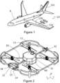
- FIG. 1 is a schematic view of a flying machine 10 according to an embodiment of the invention in use on an aircraft 9.
- the flying machine 10 moves relative to the surface of the aircraft to acquire a plurality of three-dimensional measurements of a plurality of areas of interest of the surface of the aircraft.
- This plurality of areas of interest is for example a list of areas provided by an automatic surface inspection system proposed by the applicant in the patent application.
- WO2016/203151 which allows to automatically detect a list of defects on a surface of a predetermined object.
- the invention can therefore use this list of defects as a list of areas of interest to determine the relief of each of these detected defects.
- the list of areas of interest is provided to the machine, for example, by means of a file of positions to be inspected.
- These areas of interest can be of any type (outline of doors, panels, any impacts, etc.).
- the list of areas of interest is the entire surface of the object.
- areas 12a, 12b and 12c are relatively limited areas while area 12c is an extended area that covers the entire lateral surface of the vertical drift of the aircraft 9.
- FIG 2 illustrates in more detail the flying machine 10.
- the latter comprises a supporting frame 20 on which are mounted eight lift and displacement motors 11, each motor being associated with a propeller 13. Only one motor 11 and one propeller 13 are referenced on the figure 2 for the sake of clarity.
- the means of support and movement of the machine can have other architectures without modifying the object of the invention.
- the flying machine 10 also comprises three-dimensional measuring equipment 14 configured to allow the measurement of a relief of the surface targeted by the equipment.
- This equipment is mounted on a nacelle 21 mechanically connected to the supporting frame 20 at the front of the machine defined relative to a longitudinal direction (L).
- reference 60 represents a mechanical box housing all of the control components of the machine (piloting system), tools for analyzing data from the sensors (rangefinders, inertial sensors, etc.), various processing modules (compensation module, relief map creation module, etc.), and calculation means (processor, memory, etc.), connected to the measuring equipment 14 and to the support and movement means 11 by wired connections or wireless connection means.
- the engine of the figure 2 also includes two laser rangefinders 31, 32.
- This nacelle 21 comprises a U-shaped frame 18 mounted on the frame 20 of the machine by means of a motorized pivot joint 19 allowing the U-shaped frame 18 to pivot relative to the frame 20 around an axis extending along the longitudinal direction, as defined in the figure 2 .
- the equipment 14 is itself mounted in the U-shaped frame 18 by a motorized pivot joint 22 allowing the equipment to pivot relative to the U-shaped frame 18 about an axis extending along the transverse direction, as defined in the figure 2 .
- the equipment 14 can be moved to target all directions by controlling the joints 19, 22 (which allows the rolling and pitching of the equipment to be controlled) and by controlling the yaw of the machine, which then defines the yaw of the equipment.
- the motorization of the joints 19 and 22 can be of any type and preferably comprises electric motors.
- the equipment 14 also comprises an emission source 15 of a reference wave, and a matrix receiver 16 of a wave reflected by the area of interest targeted by the equipment, and a processing unit 38, shown schematically in the figure 5 , configured to be able to determine a measurement of the relief of the area of interest targeted by the equipment 14 from the analysis of the reference wave and the reflected wave.
- the emission source 15 is a camera for emitting structured light and the matrix receiver 16 is an image acquisition camera.
- the reference and reflected waves are therefore images.
- the camera 15 for emitting structured light can be of any known type so that the structured light can be light with a particular pattern (lines, points, a grid, etc.).
- the image acquisition camera 16 then acquires images of the different patterns projected onto the area of interest.
- the processing unit 38 then makes it possible to determine the deformation of the pattern.
- the analysis of the deformation of the pattern makes it possible to estimate the depth of the surface onto which the structured light is projected. Different technical and software solutions are available on the market for estimating the depth from images acquired from the projection of the structured light and are not described here in detail.
- the emission source 15 is a laser profilometer and the matrix receiver 16 is a camera for acquiring an image of the area of interest illuminated by the laser profilometer.
- a laser profilometer projects a line onto the area of interest and the acquisition camera acquires an image of the line projected onto the area of interest.
- the processing unit 38 can then determine the depth of the area of interest along this projected line.
- Different technical and software solutions are available on the market for estimating the depth from a laser profilometer and are not described here in detail.
- the emission source 15 is a lidar flash and the matrix receiver 16 is a camera for acquiring an image of the area of interest illuminated by the lidar flash.
- the reference wave is a multidirectional laser signal emitted by a lidar flash.
- the matrix receiver acquires the wave reflected by the area of interest targeted by the emitted wave and the processing unit 38 determines the depth by comparative analysis of the emitted wave and the reflected wave (typically by measuring the time of flight or by measuring the phase shift).
- a flying machine according to this embodiment is shown schematically in the figure 3 .
- this device comprises three laser rangefinders 30, 31, 32 including a rangefinder 30 arranged in the vicinity of the measuring equipment.
- the number of laser rangefinders is not conditioned by the type of measuring equipment used. Thus, nothing prevents planning to use measuring equipment of the flash lidar type as shown in the figure 3 with two laser rangefinders or using structured light type measuring equipment as shown in the figure 2 with three laser rangefinders.
- the flying machine further comprises an automatic piloting system configured to be able to switch the machine from a mode, called navigation mode, in which the machine can be moved from an area of interest to a subsequent area of interest by controlling the motors 11, to a mode, called stabilized mode, in which the motors 11 are controlled to be able to keep constant at least one kinematic parameter of the machine (for example the position of the machine, the speed of the machine, the acceleration of the machine, the attitude of the machine or a combination of these different parameters), making it possible to minimize the vibrations of the machine in order to be able to activate the equipment 14 and to acquire a three-dimensional measurement of the area of interest.
- this piloting system is for example housed in the central housing 60 of the machine and in interaction with the sensors of the machine (laser rangefinders and internal sensor) and the motors 11.
- the automatic piloting system is preferably configured to be able, in the vicinity of each area of interest, to switch from navigation mode to stabilized mode when the craft has a state close to an anticipation state defined in relation to an acquisition state.
- machine status refers to the kinematic characteristics of the machine, such as the position of the machine, the speeds of the machine (angular and/or translational), the orientations of the measuring equipment, the accelerations of the machine, etc. This status is determined for example by laser sensors, inertial sensors and by a machine location module. This module location can be of any type and is for example that described in the patent application WO2017/121936 on behalf of the applicant.
- acquisition state refers to the state targeted by the device to achieve the acquisition of the area of interest considered. This acquisition state is determined for example by a position, a speed and an orientation of the acquisition equipment.
- vigation law refers to the law that allows, from a measured state and a given trajectory, to calculate the necessary acceleration, along the 3 axes, to follow the given trajectory.
- the calculated necessary acceleration is by nature evolving given that the state of the machine changes at each instant.
- control law refers to the law that allows, from a measured state and an acceleration instruction, to calculate the motor commands necessary to achieve the targeted acceleration.
- the acceleration at the input of the control law is that calculated by the navigation law. For example, if lateral acceleration is requested, the control law will reduce the speed of the motors on the corresponding side to tilt the machine. The output (the rotation speed of the motors) varies as much as the input (the commanded acceleration) varies. Also, in the navigation law, since the commanded acceleration is constantly varying, the same is true for the control of the actuators (the motors).
- acquisition law refers to the law which allows, from the state of the machine and the state of acquisition, the calculation of the constant kinematic parameter (in practice the acceleration) likely to lead to ideal acquisition conditions.
- Sm the measured state of the machine at a given instant characterized by the position Pm and the speed Vm at this given instant.
- piloting system preferably uses software means embedded on a component of the flying machine.
- system may comprise software and/or hardware means for implementing the different steps of the piloting system.
- the flying machine further comprises a module 36 for compensating the three-dimensional measurements acquired by the measuring equipment 14 adapted to define a movement profile of the machine during the acquisition and correct the measurements according to this movement profile.
- module means a software element, a subset of a software program, which can be compiled separately, either for independent use or for assembly with other modules of a program, or a hardware element, or a combination of a hardware element and a software subroutine.
- a module can be implemented as a computer program executed by one or more electronic components, for example a processor of a computer, microcontroller, DSP (Digital Signal Processing System) Processor in English), FPGA (Field-Programmable Gate Array in English), etc.
- a module is therefore an element (software and/or hardware) which allows a function to be performed.
- a subsequent step of data fusion and creation of a depth map can be implemented by an ad-hoc module, including possible filtering and noise rejection can be implemented (either on board the machine, or after repatriation of the data to the ground).
- a subsequent step of characterization and segmentation of the measurements can also be implemented by an ad-hoc module (either on board the machine, or on the ground after repatriation of the data to the ground).
- Different methods available in the literature make it possible to make such data segmentations.
- Performing all steps 1 to 4 for each acquisition allows the creation of a list of defects characterized by a depth map, representative quantities and a textual indication.
- global statistics can also be generated, and additional indications calculated from knowledge of all the defects.
- the density of defects can be calculated by zone, and for each defect its distance to the closest other defects. This data can be useful to better assess the acceptability or not of certain damages.
- the system can be programmed to automatically give an indication on the next step to be taken, such as a repair or monitoring, according to preprogrammed rules. These preprogrammed rules can for example be integrated into the 3D model and thus depend on the location of the defects.
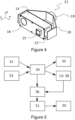
- FIG. 5 is a functional diagram of the various means implemented by the motorized flying machine for measuring the relief of a plurality of areas of interest of a surface of a predetermined object to be inspected according to a preferred embodiment of the invention.
- Such a device comprises at least one laser rangefinder 32 and at least one inertial system 33.
- Such an inertial system 33 comprises, for example, three accelerometers and three gyroscopes.
- the laser rangefinder 32 and the inertial system 33 are mounted on the frame 20 of the device or directly on the nacelle 21.
- the data from these two instruments feed a calculation module 34 of the position of the mobile machine and control of the three-dimensional measuring equipment 14.
- This module 34 controls the implementation of the control law 35 described above in connection with the control system.
- the calculation module 34 and the control law 35 form the control system.
- the compensation module 36 corrects the measurements based on the motion profile determined by the process described above.
- the machine further comprises a module for accessing a three-dimensional model of the surface of the aircraft 9 and a module for locating the relative position of the machine. 20 with respect to this three-dimensional modeling of the surface of the aircraft to be inspected, so as to be able to associate with each area of interest (12a, 12b, 12c) targeted by the measuring equipment (14) the coordinates of the area of interest in a reference frame of the three-dimensional modeling of the surface.
- This 3D modeling is for example a polygonal modeling of the surface of the object.
- the module for locating the position of the machine with respect to this 3D modeling can be of any type. It can for example be a module implementing the principles described in the patent application WO2017/121936 on behalf of the applicant.
- the corrected data can then be transmitted to a ground station 50 via a communication system 51.
- This transmission of the corrected data to a ground station 50 is for example a wireless transmission, which can be of any type.
Landscapes
- Engineering & Computer Science (AREA)
- Remote Sensing (AREA)
- Radar, Positioning & Navigation (AREA)
- Physics & Mathematics (AREA)
- General Physics & Mathematics (AREA)
- Aviation & Aerospace Engineering (AREA)
- Automation & Control Theory (AREA)
- Chemical & Material Sciences (AREA)
- Combustion & Propulsion (AREA)
- Computer Networks & Wireless Communication (AREA)
- Electromagnetism (AREA)
- Manufacturing & Machinery (AREA)
- Transportation (AREA)
- Length Measuring Devices By Optical Means (AREA)
Claims (13)
- Motorisiertes Fluggerät (10) zum Messen der Kontur mehrerer Bereiche von Interesse (12a, 12b, 12c) einer Oberfläche eines bestimmten, zu untersuchenden Objekts (9), worin das Fluggerät umfasst:- einen Tragrahmen (20),- motorisierte Mittel (11, 13) zum Anheben und Bewegen des Tragrahmens (20),- eine Vorrichtung (14) zur dreidimensionalen Erfassung eines Bereichs von Interesse (12a, 12b, 12c), auf den die Vorrichtung (14) gerichtet ist, worin die Vorrichtung auf einer Gondel (21) montiert ist, die mechanisch mit dem Tragrahmen (20) verbunden ist, worin die Vorrichtung (14) eine Wellenemissionsquelle (15), worin die Welle als Referenzwelle bezeichnet wird, einen Matrixempfänger (16) einer Welle, die von dem Bereich von Interesse (12a, 12b, 12c), auf den die Vorrichtung (14) gerichtet ist, reflektiert wird, und eine Verarbeitungseinheit (38) umfasst, die ausgestaltet ist, in der Lage zu sein, eine Erfassung der Kontur des Bereiches von Interesse (12a, 12b, 12c), auf den die Vorrichtung (14) gerichtet ist, anhand der Analyse der Referenzwelle und der reflektierten Welle zu bestimmen,- ein automatisches Steuerungssystem (34, 35) des Fluggeräts, das ausgestaltet ist, das Fluggerät von einem als Navigationsmodus bezeichneten Modus, in dem das Fluggerät von einem Bereich von Interesse (12a, 12b, 12c) zu einem nachfolgenden Bereich von Interesse (12a, 12b, 12c) bewegt werden kann, indem motorisierte Hebe- und Bewegungsmittel (11, 13) gesteuert werden, in einen als stabilisierten Modus bezeichneten Modus umzuschalten, in dem die motorisierten Hebebewegungsmittel (11, 13) so gesteuert werden, dass diese in der Lage sind, mindestens einen kinematischen Parameter des Fluggeräts konstant zu halten, ausgewählt aus der Gruppe bestehend aus der Geschwindigkeit des Fluggeräts, der Beschleunigung des Fluggeräts, der Lage des Fluggeräts und einer Funktion eines oder mehrerer dieser Parameter, wodurch es möglich ist, die Vibrationen des Fluggeräts zu minimieren, und in dem die Erfassungsvorrichtung (14) eine dreidimensionale Erfassung eines Bereiches von Interesse (12a, 12b, 12c) erfassen kann,dadurch gekennzeichnet, dass das automatische Steuerungssystem (34, 35) ausgestaltet ist, in der Nähe jedes Bereiches von Interesse vom Navigationsmodus in den stabilisierten Modus umzuschalten, wenn sich das Fluggerät in einem Zustand befindet, der durch mindestens einen kinematischen Parameter des Fluggeräts definiert ist und an einen Zustand angrenzt, der als Erwartungszustand bezeichnet wird, der durch mindestens diesen kinematischen Parameter des Fluggeräts definiert ist, und der ausgehend von einem als Aufnahmezustand bezeichneten Zustand, der einem Zielwert dieses kinematischen Parameters für die Durchführung der Aufnahme dieses Bereiches von Interesse entspricht, und einer als Antizipationszeitverzögerung bezeichneten Zeitverzögerung bestimmt wird, die der Zeit entspricht, die erforderlich ist, um zu gewährleisten, dass dieser Parameter durch das Fluggerät konstant gehalten wird, wodurch die Aufnahme einer dreidimensionalen Erfassung des Bereiches von Interesse (12a, 12b, 12c) durch die Erfassungsvorrichtung (14) ermöglicht wird.
- Fluggerät nach Anspruch 1, dadurch gekennzeichnet, dass die Gondel (21) ein motorisiertes Gelenk (22) umfasst, das mindestens eine Neigungsachse der Erfassungsvorrichtung (14) in Bezug auf den Tragrahmen (20) aufweist, um die Vorrichtung (14) gegenüber einem zu messenden Bereich von Interesse (12a, 12b, 12c) positionieren zu können.
- Fluggerät nach einem der Ansprüche 1 oder 2, dadurch gekennzeichnet, dass es ferner mindestens einen Laserentfernungsmesser (30, 31, 32) umfasst, der starr mit dem Tragrahmen (20) oder der Gondel (21) verbunden ist und der einen Sensor für die relative Position des Fluggeräts in Bezug auf die Oberfläche des zu inspizierenden Objekts bildet.
- Fluggerät nach Anspruch 3, dadurch gekennzeichnet, dass das automatische Steuerungssystem (34, 35) ausgestaltet ist, den Wechsel in den stabilisierten Modus zu steuern, sobald der/die Laserentfernungsmesser (30, 31, 32) feststellt/feststellen, dass sich das Fluggerät an einer bestimmten Position des Bereiches von Interesse (12a, 12b, 12c) befindet.
- Fluggerät nach einem der Ansprüche 1 bis 4, dadurch gekennzeichnet, dass es ferner ein Modul (36) zur Kompensation der von der Vorrichtung (14) aufgenommenen dreidimensionalen Erfassungen umfasst, das geeignet ist, ein Bewegungsprofil des Fluggeräts während der Aufnahme zu definieren und die Erfassungen auf der Grundlage dieses Bewegungsprofils zu korrigieren.
- Fluggerät nach einem der Ansprüche 1 bis 5, dadurch gekennzeichnet, dass es zudem ein Modul für den Zugriff auf ein dreidimensionales Modell der Oberfläche des Objekts und ein Modul für die Bestimmung der relativen Position des Fluggeräts in Bezug auf das dreidimensionale Modell der Oberfläche des zu untersuchenden Objekts umfasst, so dass es in der Lage ist, jedem von der Erfassungsvorrichtung (14) anvisierten Bereich von Interesse (12a, 12b, 12c) die Koordinaten des Bereiches von Interesse in einem Bezugspunkt des dreidimensionalen Modells der Oberfläche zuzuordnen.
- Fluggerät nach einem der Ansprüche 1 bis 6, dadurch gekennzeichnet, dass dieses ferner ein Modul (51) zur drahtlosen Übertragung der Konturerfassungen an eine Bodenstation (50) umfasst.
- Fluggerät nach einem der Ansprüche 1 bis 7, dadurch gekennzeichnet, dass dieses ferner ein Modul zur Bestimmung einer Tiefenkarte umfasst, das ein Untermodul zur Bestimmung einer Referenzkontur der Oberfläche des untersuchten Objekts aus einem bestimmten 3D-Modell der Oberfläche des untersuchten Objekts in Verbindung mit einem bestimmten mathematischen Modell und ein Untermodul zur Berechnung der Tiefenunterschiede zwischen den Erfassungen der Kontur der bestimmten Bereiche und der Referenzkontur umfasst.
- Fluggerät nach einem der Ansprüche 1 bis 8, dadurch gekennzeichnet, dass die dreidimensionale Erfassungsvorrichtung (14) eine Kamera zur Emission von strukturiertem Licht, die die Emissionsquelle (15) der Referenzwelle bildet, und eine Kamera zur Erfassung von Bildern des durch strukturiertes Licht beleuchteten Bereiches von Interesse umfasst, die den Matrixempfänger (16) der reflektierten Welle bildet.
- Fluggerät nach einem der Ansprüche 1 bis 8, dadurch gekennzeichnet, dass die dreidimensionale Erfassungsvorrichtung (14) ein Laserprofilometer, das die Emissionsquelle (15) der Referenzwelle bildet, und eine Kamera zum Erfassen von Bildern des durch das Laserprofilometer beleuchteten Bereiches von Interesse umfasst, die den Matrixempfänger (16) der reflektierten Welle bildet.
- Fluggerät nach einem der Ansprüche 1 bis 8, dadurch gekennzeichnet, dass die dreidimensionale Erfassungsvorrichtung (14) einen Blitz-Lidar, der die Emissionsquelle (15) der Referenzwelle bildet, und eine Kamera zur Erfassung von Bildern des durch den Blitz-Lidar beleuchteten Bereiches von Interesse umfasst, die den Matrixempfänger (16) der reflektierten Welle bildet.
- Fluggerät nach einem der Ansprüche 1 bis 11, dadurch gekennzeichnet, dass die motorisierten Mittel (11, 13) zum Heben und Bewegen des Fluggeräts mindestens vier Antriebsmotoren umfassen.
- Verfahren zur Steuerung eines motorisierten Fluggeräts (10) nach einem der Ansprüche 1 bis 12, dadurch gekennzeichnet, dass es die Schritte umfasst:- Definieren einer Liste von Bereiches von Interesse (12a, 12b, 12c) einer Oberfläche eines bestimmten zu untersuchenden Objekts,- Definieren eines Navigationsprofils des Fluggeräts zwischen den verschiedenen Bereichen von Interesse (12a, 12b, 12c) gemäß einer bestimmten Chronologie,- Bewegen des Fluggeräts (20) in Richtung eines ersten Bereiches von Interesse,- Einstellen der Gondel (21) des Fluggeräts, so dass diese auf den mit der dreidimensionalen Erfassungsvorrichtung (14) zu messenden Bereich zeigt,- in unmittelbarer Nähe des Bereiches von Interesse, Umschalten des Fluggeräts in den stabilisierten Modus und Auslösen der Aufnahme der dreidimensionalen Erfassung des Bereiches von Interesse,- Umschalten des Fluggeräts in den Navigationsmodus, wenn die Aufnahme abgeschlossen ist,- Bewegen des Fluggeräts in Richtung des nächsten Bereiches von Interesse des Navigationsprofils und Wiederholen der vorhergehenden Vorgänge bis zum letzten Bereiches von Interesse des genannten Navigationsprofils.
Applications Claiming Priority (2)
| Application Number | Priority Date | Filing Date | Title |
|---|---|---|---|
| FR1856985A FR3084485B1 (fr) | 2018-07-26 | 2018-07-26 | Engin volant motorise de mesure du relief de surfaces d'un objet predetermine et procede de commande d'un tel engin |
| PCT/FR2019/051822 WO2020021191A1 (fr) | 2018-07-26 | 2019-07-22 | Engin volant motorisé de mesure du relief de surfaces d'un objet prédéterminé et procédé de commande d'un tel engin |
Publications (3)
| Publication Number | Publication Date |
|---|---|
| EP3827320A1 EP3827320A1 (de) | 2021-06-02 |
| EP3827320C0 EP3827320C0 (de) | 2024-09-04 |
| EP3827320B1 true EP3827320B1 (de) | 2024-09-04 |
Family
ID=63684155
Family Applications (1)
| Application Number | Title | Priority Date | Filing Date |
|---|---|---|---|
| EP19790630.8A Active EP3827320B1 (de) | 2018-07-26 | 2019-07-22 | Motorisiertes luftfahrzeug zum messen des reliefs von oberflächen eines vorbestimmten objekts und verfahren zur steuerung eines solchen luftfahrzeugs |
Country Status (6)
| Country | Link |
|---|---|
| US (1) | US11964763B2 (de) |
| EP (1) | EP3827320B1 (de) |
| ES (1) | ES2990214T3 (de) |
| FR (1) | FR3084485B1 (de) |
| PL (1) | PL3827320T3 (de) |
| WO (1) | WO2020021191A1 (de) |
Families Citing this family (6)
| Publication number | Priority date | Publication date | Assignee | Title |
|---|---|---|---|---|
| US11794342B2 (en) * | 2020-07-17 | 2023-10-24 | Intrinsic Innovation Llc | Robot planning using unmanned aerial vehicles |
| FR3116902B1 (fr) | 2020-11-27 | 2023-05-05 | Airbus Operations Sas | Procede pour detecter d’eventuels enfoncements sur une surface apte a reflechir la lumiere |
| US12148205B2 (en) | 2021-11-10 | 2024-11-19 | Skydio, Inc. | Contour scanning with an unmanned aerial vehicle |
| EP4429950B1 (de) | 2021-11-10 | 2026-03-11 | Skydio, Inc. | Konturabtastung mit einem unbemannten luftfahrzeug |
| AU2023204586A1 (en) * | 2022-07-12 | 2024-02-01 | Joy Global Underground Mining Llc | Offboard monitoring system |
| US20250137386A1 (en) * | 2023-10-30 | 2025-05-01 | Rtx Corporation | Gas turbine engine drone inspection system |
Citations (1)
| Publication number | Priority date | Publication date | Assignee | Title |
|---|---|---|---|---|
| WO2017186515A1 (de) * | 2016-04-25 | 2017-11-02 | Siemens Aktiengesellschaft | Flugmobil zum scannen eines objekts und system zur schadensanalyse des objekts |
Family Cites Families (11)
| Publication number | Priority date | Publication date | Assignee | Title |
|---|---|---|---|---|
| GB201411293D0 (en) * | 2014-06-25 | 2014-08-06 | Pearson Eng Ltd | Improvements in or relating to inspection systems |
| FR3037429B1 (fr) | 2015-06-15 | 2018-09-07 | Donecle | Systeme et procede d'inspection automatique de surface |
| FR3038109B1 (fr) * | 2015-06-29 | 2018-07-27 | Airbus Operations (S.A.S.) | Systeme et procede de localisation d'impacts sur une surface externe |
| DE102015120660A1 (de) * | 2015-11-27 | 2017-06-01 | Airbus Defence and Space GmbH | Luftfahrzeuginspektionssystem |
| FR3046848B1 (fr) | 2016-01-14 | 2018-01-05 | Donecle | Procede et systeme de determination de la position d'un engin mobile |
| ITUA20161534A1 (it) * | 2016-03-10 | 2017-09-10 | Wpweb Srl | Procedimento per analizzare un velivolo, relativo sistema di analisi di un velivolo e sistema di sghiacciamento e/o antigelo |
| GB2558251B (en) * | 2016-12-23 | 2019-12-04 | Caterpillar Sarl | A method of operating a work machine |
| US11099581B2 (en) * | 2017-09-28 | 2021-08-24 | Gopro, Inc. | Position-based control of unmanned aerial vehicles |
| US12006066B2 (en) * | 2019-05-29 | 2024-06-11 | Ultraview Ai Inc. | UAV-based aviation inspection systems and related methods |
| FR3116902B1 (fr) * | 2020-11-27 | 2023-05-05 | Airbus Operations Sas | Procede pour detecter d’eventuels enfoncements sur une surface apte a reflechir la lumiere |
| FR3116806B1 (fr) * | 2020-11-27 | 2022-11-11 | Airbus Operations Sas | Drone volant pour l’inspection de surfaces et procédé d’inspection de surfaces au moyen d’un tel drone volant |
-
2018
- 2018-07-26 FR FR1856985A patent/FR3084485B1/fr active Active
-
2019
- 2019-07-22 WO PCT/FR2019/051822 patent/WO2020021191A1/fr not_active Ceased
- 2019-07-22 US US17/256,648 patent/US11964763B2/en active Active
- 2019-07-22 ES ES19790630T patent/ES2990214T3/es active Active
- 2019-07-22 EP EP19790630.8A patent/EP3827320B1/de active Active
- 2019-07-22 PL PL19790630.8T patent/PL3827320T3/pl unknown
Patent Citations (1)
| Publication number | Priority date | Publication date | Assignee | Title |
|---|---|---|---|---|
| WO2017186515A1 (de) * | 2016-04-25 | 2017-11-02 | Siemens Aktiengesellschaft | Flugmobil zum scannen eines objekts und system zur schadensanalyse des objekts |
Also Published As
| Publication number | Publication date |
|---|---|
| EP3827320A1 (de) | 2021-06-02 |
| US11964763B2 (en) | 2024-04-23 |
| EP3827320C0 (de) | 2024-09-04 |
| PL3827320T3 (pl) | 2024-12-16 |
| WO2020021191A1 (fr) | 2020-01-30 |
| FR3084485A1 (fr) | 2020-01-31 |
| US20210261251A1 (en) | 2021-08-26 |
| FR3084485B1 (fr) | 2022-08-05 |
| ES2990214T3 (es) | 2024-11-29 |
Similar Documents
| Publication | Publication Date | Title |
|---|---|---|
| EP3827320B1 (de) | Motorisiertes luftfahrzeug zum messen des reliefs von oberflächen eines vorbestimmten objekts und verfahren zur steuerung eines solchen luftfahrzeugs | |
| CA2989154C (fr) | Systeme et procede d'inspection automatique de surface | |
| JP7025156B2 (ja) | データ処理装置、データ処理方法およびデータ処理用プログラム | |
| EP2400460B1 (de) | Bewertungsverfahren der horizontalen Geschwindigkeit einer Drohne, insbesondere einer Drohne mit über den Autopiloten gesteuertem stationärem Flug | |
| WO2009046519A1 (fr) | Système et méthode de cartographie tridimensionnelle d'une surface structurelle | |
| FR2938072A1 (fr) | Procede de traitement de signaux d'un radar aeroporte avec correction de l'erreur de l'angle de pointage du faisceau radar et dispositif correspondant | |
| EP2818829B1 (de) | Navigationssystem, zeigegerät, und kalibrierungsverfahren eines navigationsystems und zeigegeräts. | |
| EP3403117A1 (de) | Verfahren und system zur bestimmung der position eines sich bewegenden fahrzeugs | |
| FR3129737A1 (fr) | Systeme et procede de navigation autonome base vision d’un satellite | |
| EP0268509A1 (de) | Optoelektronisches Verfahren und Gerät zur Echtzeitmessung der Bewegungen eines unter Flüssigkeitseinfluss stehenden Festkörpers | |
| EP4205406B1 (de) | Verfahren zur erfassung von bildern eines raumobjekts im terrestrischen orbit durch ein raumfahrzeug im terrestrischen orbit | |
| FR3116806A1 (fr) | Drone volant pour l’inspection de surfaces et procédé d’inspection de surfaces au moyen d’un tel drone volant | |
| EP3333539A1 (de) | Elektronische vorrichtung zum steuern einer drohne, entsprechende drohne, entsprechendes steuerverfahren und computerprogramm | |
| FR2938075A1 (fr) | Dispositif et procede de detection et de mesure de vent pour aeronef | |
| EP3776471B1 (de) | Verfahren zum auffinden eines ziels aus einer elliptischen kontur | |
| EP3435329A1 (de) | Elektronische vorrichtung und verfahren zum schätzen einer szenenverschiebung, die von einer drohne beobachtet wird, elektronisches gerät zur berechnung der bodengeschwindigkeit der drohne, entsprechende drohne und entsprechendes computerprogramm | |
| CA3048013C (fr) | Procede et drone muni d'un systeme d'aide a l'atterrissage/decollage | |
| FR3145416A1 (fr) | Engin du type multi-rotors et procede d’inspection d’une surface verticale au moyen d’un tel engin | |
| WO2020157425A1 (fr) | Procede de localisation | |
| WO2016151243A1 (fr) | Dispositif et procédé de détermination de la teneur en eau dans l'atmosphère, dispositif et procédé de détection de conditions givrantes et programmes d'ordinateur | |
| FR2938228A1 (fr) | Procede de mesure de distance au moyen d'une camera embarquee dans un vehicule automobile | |
| EP3620852A1 (de) | Luftbildaufnahmeverfahren einer geografischen zone, 3d-kartografieverfahren einer geografischen zone und luftfahrzeug zur ausführung dieses verfahren | |
| FR2545613A1 (fr) | Appareil de mesure de la vitesse d'un objet, notamment d'un aeronef | |
| WO2021156026A1 (fr) | Procédé de calibration des caractéristiques extrinsèques d'un lidar | |
| EP4430362B1 (de) | Hybrides trägheits-/sternnavigationsverfahren mit harmonisierungsleistungsindikator |
Legal Events
| Date | Code | Title | Description |
|---|---|---|---|
| STAA | Information on the status of an ep patent application or granted ep patent |
Free format text: STATUS: UNKNOWN |
|
| STAA | Information on the status of an ep patent application or granted ep patent |
Free format text: STATUS: THE INTERNATIONAL PUBLICATION HAS BEEN MADE |
|
| PUAI | Public reference made under article 153(3) epc to a published international application that has entered the european phase |
Free format text: ORIGINAL CODE: 0009012 |
|
| STAA | Information on the status of an ep patent application or granted ep patent |
Free format text: STATUS: REQUEST FOR EXAMINATION WAS MADE |
|
| 17P | Request for examination filed |
Effective date: 20210226 |
|
| AK | Designated contracting states |
Kind code of ref document: A1 Designated state(s): AL AT BE BG CH CY CZ DE DK EE ES FI FR GB GR HR HU IE IS IT LI LT LU LV MC MK MT NL NO PL PT RO RS SE SI SK SM TR |
|
| DAV | Request for validation of the european patent (deleted) | ||
| DAX | Request for extension of the european patent (deleted) | ||
| STAA | Information on the status of an ep patent application or granted ep patent |
Free format text: STATUS: EXAMINATION IS IN PROGRESS |
|
| 17Q | First examination report despatched |
Effective date: 20220322 |
|
| REG | Reference to a national code |
Ref country code: DE Ref legal event code: R079 Free format text: PREVIOUS MAIN CLASS: G05D0001000000 Ipc: G01C0021000000 Ref country code: DE Ref legal event code: R079 Ref document number: 602019058353 Country of ref document: DE Free format text: PREVIOUS MAIN CLASS: G05D0001000000 Ipc: G01C0021000000 |
|
| GRAP | Despatch of communication of intention to grant a patent |
Free format text: ORIGINAL CODE: EPIDOSNIGR1 |
|
| STAA | Information on the status of an ep patent application or granted ep patent |
Free format text: STATUS: GRANT OF PATENT IS INTENDED |
|
| RIC1 | Information provided on ipc code assigned before grant |
Ipc: B64D 43/00 20060101ALI20240126BHEP Ipc: G01C 21/00 20060101AFI20240126BHEP |
|
| INTG | Intention to grant announced |
Effective date: 20240221 |
|
| GRAS | Grant fee paid |
Free format text: ORIGINAL CODE: EPIDOSNIGR3 |
|
| RAP3 | Party data changed (applicant data changed or rights of an application transferred) |
Owner name: DONECLE |
|
| GRAA | (expected) grant |
Free format text: ORIGINAL CODE: 0009210 |
|
| STAA | Information on the status of an ep patent application or granted ep patent |
Free format text: STATUS: THE PATENT HAS BEEN GRANTED |
|
| AK | Designated contracting states |
Kind code of ref document: B1 Designated state(s): AL AT BE BG CH CY CZ DE DK EE ES FI FR GB GR HR HU IE IS IT LI LT LU LV MC MK MT NL NO PL PT RO RS SE SI SK SM TR |
|
| REG | Reference to a national code |
Ref country code: GB Ref legal event code: FG4D Free format text: NOT ENGLISH |
|
| REG | Reference to a national code |
Ref country code: CH Ref legal event code: EP |
|
| REG | Reference to a national code |
Ref country code: IE Ref legal event code: FG4D Free format text: LANGUAGE OF EP DOCUMENT: FRENCH |
|
| REG | Reference to a national code |
Ref country code: DE Ref legal event code: R096 Ref document number: 602019058353 Country of ref document: DE |
|
| U01 | Request for unitary effect filed |
Effective date: 20240909 |
|
| U07 | Unitary effect registered |
Designated state(s): AT BE BG DE DK EE FI FR IT LT LU LV MT NL PT RO SE SI Effective date: 20240925 |
|
| REG | Reference to a national code |
Ref country code: ES Ref legal event code: FG2A Ref document number: 2990214 Country of ref document: ES Kind code of ref document: T3 Effective date: 20241129 |
|
| PG25 | Lapsed in a contracting state [announced via postgrant information from national office to epo] |
Ref country code: NO Free format text: LAPSE BECAUSE OF FAILURE TO SUBMIT A TRANSLATION OF THE DESCRIPTION OR TO PAY THE FEE WITHIN THE PRESCRIBED TIME-LIMIT Effective date: 20241204 |
|
| PG25 | Lapsed in a contracting state [announced via postgrant information from national office to epo] |
Ref country code: GR Free format text: LAPSE BECAUSE OF FAILURE TO SUBMIT A TRANSLATION OF THE DESCRIPTION OR TO PAY THE FEE WITHIN THE PRESCRIBED TIME-LIMIT Effective date: 20241205 |
|
| PG25 | Lapsed in a contracting state [announced via postgrant information from national office to epo] |
Ref country code: HR Free format text: LAPSE BECAUSE OF FAILURE TO SUBMIT A TRANSLATION OF THE DESCRIPTION OR TO PAY THE FEE WITHIN THE PRESCRIBED TIME-LIMIT Effective date: 20240904 |
|
| PG25 | Lapsed in a contracting state [announced via postgrant information from national office to epo] |
Ref country code: RS Free format text: LAPSE BECAUSE OF FAILURE TO SUBMIT A TRANSLATION OF THE DESCRIPTION OR TO PAY THE FEE WITHIN THE PRESCRIBED TIME-LIMIT Effective date: 20241204 |
|
| PG25 | Lapsed in a contracting state [announced via postgrant information from national office to epo] |
Ref country code: RS Free format text: LAPSE BECAUSE OF FAILURE TO SUBMIT A TRANSLATION OF THE DESCRIPTION OR TO PAY THE FEE WITHIN THE PRESCRIBED TIME-LIMIT Effective date: 20241204 Ref country code: NO Free format text: LAPSE BECAUSE OF FAILURE TO SUBMIT A TRANSLATION OF THE DESCRIPTION OR TO PAY THE FEE WITHIN THE PRESCRIBED TIME-LIMIT Effective date: 20241204 Ref country code: HR Free format text: LAPSE BECAUSE OF FAILURE TO SUBMIT A TRANSLATION OF THE DESCRIPTION OR TO PAY THE FEE WITHIN THE PRESCRIBED TIME-LIMIT Effective date: 20240904 Ref country code: GR Free format text: LAPSE BECAUSE OF FAILURE TO SUBMIT A TRANSLATION OF THE DESCRIPTION OR TO PAY THE FEE WITHIN THE PRESCRIBED TIME-LIMIT Effective date: 20241205 |
|
| PG25 | Lapsed in a contracting state [announced via postgrant information from national office to epo] |
Ref country code: IS Free format text: LAPSE BECAUSE OF FAILURE TO SUBMIT A TRANSLATION OF THE DESCRIPTION OR TO PAY THE FEE WITHIN THE PRESCRIBED TIME-LIMIT Effective date: 20250104 |
|
| PG25 | Lapsed in a contracting state [announced via postgrant information from national office to epo] |
Ref country code: SM Free format text: LAPSE BECAUSE OF FAILURE TO SUBMIT A TRANSLATION OF THE DESCRIPTION OR TO PAY THE FEE WITHIN THE PRESCRIBED TIME-LIMIT Effective date: 20240904 |
|
| PG25 | Lapsed in a contracting state [announced via postgrant information from national office to epo] |
Ref country code: CZ Free format text: LAPSE BECAUSE OF FAILURE TO SUBMIT A TRANSLATION OF THE DESCRIPTION OR TO PAY THE FEE WITHIN THE PRESCRIBED TIME-LIMIT Effective date: 20240904 |
|
| PG25 | Lapsed in a contracting state [announced via postgrant information from national office to epo] |
Ref country code: SK Free format text: LAPSE BECAUSE OF FAILURE TO SUBMIT A TRANSLATION OF THE DESCRIPTION OR TO PAY THE FEE WITHIN THE PRESCRIBED TIME-LIMIT Effective date: 20240904 |
|
| PGFP | Annual fee paid to national office [announced via postgrant information from national office to epo] |
Ref country code: PL Payment date: 20250618 Year of fee payment: 7 |
|
| PLBE | No opposition filed within time limit |
Free format text: ORIGINAL CODE: 0009261 |
|
| STAA | Information on the status of an ep patent application or granted ep patent |
Free format text: STATUS: NO OPPOSITION FILED WITHIN TIME LIMIT |
|
| 26N | No opposition filed |
Effective date: 20250605 |
|
| U20 | Renewal fee for the european patent with unitary effect paid |
Year of fee payment: 7 Effective date: 20250728 |
|
| PGFP | Annual fee paid to national office [announced via postgrant information from national office to epo] |
Ref country code: ES Payment date: 20250827 Year of fee payment: 7 |
|
| PGFP | Annual fee paid to national office [announced via postgrant information from national office to epo] |
Ref country code: GB Payment date: 20250722 Year of fee payment: 7 |
|
| PGFP | Annual fee paid to national office [announced via postgrant information from national office to epo] |
Ref country code: CH Payment date: 20250801 Year of fee payment: 7 |