EP0268509A1 - Optoelektronisches Verfahren und Gerät zur Echtzeitmessung der Bewegungen eines unter Flüssigkeitseinfluss stehenden Festkörpers - Google Patents
Optoelektronisches Verfahren und Gerät zur Echtzeitmessung der Bewegungen eines unter Flüssigkeitseinfluss stehenden Festkörpers Download PDFInfo
- Publication number
- EP0268509A1 EP0268509A1 EP87402308A EP87402308A EP0268509A1 EP 0268509 A1 EP0268509 A1 EP 0268509A1 EP 87402308 A EP87402308 A EP 87402308A EP 87402308 A EP87402308 A EP 87402308A EP 0268509 A1 EP0268509 A1 EP 0268509A1
- Authority
- EP
- European Patent Office
- Prior art keywords
- light spots
- image
- coordinates
- video cameras
- cameras
- Prior art date
- Legal status (The legal status is an assumption and is not a legal conclusion. Google has not performed a legal analysis and makes no representation as to the accuracy of the status listed.)
- Granted
Links
Images





Classifications
-
- B—PERFORMING OPERATIONS; TRANSPORTING
- B63—SHIPS OR OTHER WATERBORNE VESSELS; RELATED EQUIPMENT
- B63B—SHIPS OR OTHER WATERBORNE VESSELS; EQUIPMENT FOR SHIPPING
- B63B39/00—Equipment to decrease pitch, roll, or like unwanted vessel movements; Apparatus for indicating vessel attitude
- B63B39/14—Equipment to decrease pitch, roll, or like unwanted vessel movements; Apparatus for indicating vessel attitude for indicating inclination or duration of roll
-
- G—PHYSICS
- G01—MEASURING; TESTING
- G01B—MEASURING LENGTH, THICKNESS OR SIMILAR LINEAR DIMENSIONS; MEASURING ANGLES; MEASURING AREAS; MEASURING IRREGULARITIES OF SURFACES OR CONTOURS
- G01B11/00—Measuring arrangements characterised by the use of optical techniques
Definitions
- the subject of the present invention is a method and an opto-electronic device for real-time measurement of the movements of a mobile solid structure subjected to the effect of a fluid, such as a model airplane in a wind tunnel, a drilling platform or a nautical machine model placed in a test basin.
- a fluid such as a model airplane in a wind tunnel, a drilling platform or a nautical machine model placed in a test basin.
- the latter case of floating structure in a test basin will be considered more particularly.
- Measuring the attitude of models of boats in hydrodynamic tests in basins where it is possible to generate swells of varying amplitude and frequency is particularly important for predicting the behavior of the boat in real sailing conditions.
- the attitude of models is generally measured using a mechanical tracker located at the rear of the boat. This has drawbacks insofar as it is always necessary to have mechanical contact between the object to be studied and the metrological system.
- the present invention aims to eliminate any mechanical contact between the structure to be studied and the measurement device and to allow the determination in real time, and therefore the monitoring of the evolution over time on the one hand of the coordinates Xg, Yg, Zg of the center of gravity (or barycenter) of the structure representing, in the case of a boat, respectively the run, the swerve and the heaving of the boat compared to a fixed reference linked to the test basin, and other share of the angles ⁇ of pitch or attitude ⁇ of roll or gite and ⁇ of heading or yaw of the movement of the solid around its center of gravity.
- a device characterized in that it comprises at least four non-aligned light spots arranged in a predetermined manner on the floating structure to be monitored, at least two synchronized video cameras whose position is defined relative to a fixed reference point and is determined so as to place in the common field of vision of the cameras a set of at least three light spots, each light spot has dimensions such that, in the image plane of each of the video cameras, the image of each light spot is intercepted by a number of scanning lines of between approximately five and fifteen, the video signals delivered by the video cameras are applied to a processing device comprising analog circuits for extracting synchronization signals and acquiring image coordinates of points singular on the image, the luminance of which exceeds a predetermined level, circuits for counting and memorizing the coordinates and lengths of segments of the light spots intercepted by scanning lines of each of the video cameras, of the control and interface connected to a computer to determine the image coordinates of the barycentres of light spots in the image plane of a camera, then the coordinates of
- the device further comprises means for calculating the parameters (cavally x, swerve y, yaw or course ⁇ ,) defining the trajectory of the floating structure and means for controlling the position of the trajectory of the structure floating by comparison of the measured parameters with a setpoint.
- the device according to the invention makes it possible to measure with good precision, and without constraining mechanical connection with the floating structure to be studied, the attitudes of this structure in motion subjected to the action of swell, wind or current.
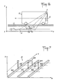
- FIG. 1 a solid structure 1, such as a model of a boat or nautical craft, floating in a test basin above which are placed two video cameras 11, 12 placed at a fixed station so that their field of vision includes light spots 71, 72, 73, 74 arranged on the structure 1 in predetermined locations.
- the image plane Pi1 and the pupil center S1 of the camera lens have been shown for the video camera 11.
- the cameras 11, 12 can be constituted by cameras with image analysis tube or, preferably, by photodiode cameras such as CCD cameras.
- CCD cameras were used, the resolution of which is 384 elements per line on 576 lines, the size of the photo-elements being 12 ⁇ m ⁇ 12 ⁇ m.
- Such cameras can operate with a maximum frame frequency of 90 Hz.
- the video signals delivered by the two synchronized cameras 11, 12 are applied to a processing and calculation device 9 which comprises a computer 5 and interface circuits ensuring the acquisition and processing of the video signals delivered by the cameras 11, 12.
- These interface circuits include analog processing circuits 2 which include circuits for extracting synchronization signals and for acquiring singular points of the image in order to take into account the images of the light sources 71, 72, 73, 74.
- Counting and storage circuits 3 develop the coordinates and the lengths of segments of the different light spots identified in the image planes of the cameras 11, 12.
- circuits 4 of the interface proper and of control provide the connections by buses 6 between the counting circuits 3 and the computer 5.
- the interface circuits 4 include in particular a clock and buffer circuits.
- FIG. 2 shows the image 7 of a light spot 71, 72 73 or 74, seen in the image plane of a camera 11 or 12. As can be seen, image 7 of the light spot is intercepted by several scanning lines Y1 to Y7.
- the size of the light spots 71, 72, 73, 74 and the location of the cameras 11, 12 relative to the structure 1 are such that the image 7 of each spot 71, 72, 73, 74 in the plane of the photosensitive target of each camera 11, 12 intercepts between about five and fifteen scan lines of the camera.
- the analog processing circuits associated with the counters 3 then identify the x, y coordinates of each light segment of the image 7 of a spot in the image plane of a camera, and determine the length Dx of each light segment making up the image of the spot.
- FIG. 2 the image 7 of a light spot constituted by a set of seven segments of different lengths constituted by the portions of scanning lines which intercept the image 7 of the light spot.
- the video signal processing device and the computer 5 cooperate to determine the barycenter of the image 7 of each light spot 71, 72, 73 observed by a camera 11 or 12, which significantly increases the accuracy of the location of the bright spots.
- a software for the acquisition of singular points is responsible for restoring in real time the barycenter of the light spots identifying the object to be tracked.
- real time means that the result must be obtained within 16.6 ms (which corresponds to a frame frequency of 60Hz).
- the information is contained for example in a table of 32 bytes. This contains on the first two words, the number of the current frame, the ordinate Yo of the first (according to the direction of line scanning) light segment composing the particle, the number of light segments which define the particle. The remaining fourteen words are used to precisely define the geometry of the spot; We find there the abscissa Xi of detection of each segment as well as their length DXi. Light spots are therefore subject to intercepting at most 14 lines of the camera matrix.
- the useful information is contained in ten bytes.
- the image coordinates of the barycenter are stored on two four bytes and the frame number on two bytes.
- the software that processes the information triples (X, Y, DX) is structured as follows:
- a core 53 (scheduler) organizes the distribution of the tasks as a function of external events, namely the presence of information in the interface 4 or the presence of particles to be treated.
- the kernel 53 tests two variables. If information is available in the interface, the acquisition and sorting procedure 52 is called. Otherwise, it comes to test if the triplet tables are full (step 56) and if so the procedure for calculating the barycenter 55 is activated.
- the acquisition and sorting procedure 52 the flowchart of which is shown in Tables I and II, reads the triplet X, Y, DX in the interface. It then checks whether this segment belongs to a particle already listed in the current frame. The search is performed according to the X and Y values; if, on the previous line (Y-1), there is a segment such that X - p ⁇ X ⁇ X + p (Y-1) (Y) (Y-1) where p is a parameterized length, then, the X and DX information is saved in the table corresponding to the particle, and the index NB is incremented.
- a new table is allocated, corresponding to the meeting of the particle.
- the address of this table is obtained by an address table containing 1024 entry points.
- X, Y, DX are stored in this table and the index NB is initialized to 1.
- the procedure for calculating the barycenter is shown in Table III. It maintains an index which indicates the address of the next table to be processed. The calculation of the barycenter is then carried out and saved in a results table whose dimension is 128 KB.
- the opto-electronic device aims to make it possible to calculate precisely, with respect to a fixed reference frame linked to the test platform, the coordinates Xg, Yg, Zg of the center of gravity G of the floating structure 1 to observe.
- At least two video cameras 11, 12 are used so as to observe the floating structure 1 along two different viewing axes, which, preferably, form an angle of 90 ° between them.
- the cameras 11, 12 are arranged so as to each incorporate in their field of vision at least three common light spots 71, 72, 73 arranged on the structure to be studied 1.
- the device performs a stereoscopic aiming and, starting from image coordinates of each of the light spots provided by each of the cameras, it is possible to determine all of the movements of the floating structure.
- An advantageous embodiment consists of a set of four light spots 71 to 74 placed in the field of view of each of the cameras 11, 12 to achieve a totally stereoscopic vision.
- three of the light spots 71 to 73 can be placed on the upper face of the floating object 1 (FIG. 1) while the fourth spot 74 is placed at a certain height above the other spots 71, 72, 73.
- the cameras 11, 12 are then placed so as to "dive" onto the object 1. This embodiment ensures reliability of the measurements without the amount of information to be taken into account being excessive.
- the number of light spots placed on the floating structure 1 can be equal to five.
- the spots 71 to 75 can then be distributed over the two branches of a V, one of the spots 73 constituting the apex of the V and the spots defining two series of three aligned spots 71, 72, 73 and 73 , 74, 75.
- FIG. 5 represents yet another embodiment with semi-stereoscopic aim.
- seven light spots 71 to 77 are distributed so as to form two Vs, three of the light spots 73,74, 75 constituting an alignment which is common to the two Vs and is placed in the field of each of the two cameras 11, 12, whose image planes are Pi1 and Pi2.
- S1 and S2 respectively represent the pupil center of the objective of each of the cameras 11, 12.
- the embodiment of FIG. 5 remains however more complex than that of FIG. 1 which only implements four light spots 71 to 74, and the three-dimensional rendering of an object can be carried out precisely using four light sources placed on the object, as soon as two optical sensors 11, 12 are used.
- FIG. 6 schematically shows a test basin with a fixed platform 13, a body of water 14 on which is placed a floating structure 1 to be studied, and a carriage 10 carrying the cameras 11, 12 as well as the system of acquisition data associated with the cameras 11, 12.
- the carriage 10 is positioned in such a way that the light spots 71, 72, 73, 74 remain in the field of the cameras 11, 12, even in the presence of swell.
- the measurement device thus makes it possible to follow the evolutions of the model 1 permanently and to determine its three translational movements and its three rotational movements.
- the light spots 81 to 89 which are preferably five to fifteen in number, are distributed in at least two different planes so as to allow calibration for the entire space where then the light spots 71 to 74 of a model will be likely to be due to movements of the model.
- the removable structure 8 is removed and the cameras 11, 12 remain in the position they occupied during the calibration to observe an object 1 to be studied which is placed in the basin in the area where the structure 8 had been previously arranged. Thanks to the calibration, all the parameters necessary for the calculation of the position of the center of gravity of the object 1 in the fixed frame OXYZ from the image coordinates of the light spots 71 to 74 in the image planes of the cameras 11, 12 , are well determined.
- the calibration structure 8 can be formed of a simple network of horizontal and vertical bars on which the light spots are placed.
- the light spots 81 to 89 used for calibration are of the same nature as the light spots 71 to 74 used for measurements and can be done in different ways.
- light spots can be formed from sets of light emitting diodes, or from sources such as incandescent lamps.
- the light spots can also be simple reflectors illuminated by projectors 70 placed outside the field of vision of the cameras.
- the two video cameras 11 and 12 must work in synchronism.
- the camera 11 can thus constitute a "master” camera while the camera 12 operates as a “slave” and receives from the camera 11 the frame synchronization signals ST and line SL as well as the clock which gives the point frequency (frequency of analysis of photo-sensitive cells).
- the electronic measurement system essentially comprises four main blocks, two of which are common to the two channels and two are duplicated for each of the measurement channels, which constitutes a total of six modules.
- a 4 ⁇ clock provides the image coordinates of the points analyzed. It also detects the parity of the frame and ensures the system is reset to zero at the start of the acquisition, which always begins with an odd frame.
- a 4 ⁇ sequencer generates the different control signals to the modules constituting the two channels of the measurement chain.
- the 4 ⁇ clock and the 4 ⁇ sequencer are common to the two measurement channels.
- the measurement modules 2 ⁇ , 2 ⁇ are identical for the two cameras. They give the image coordinates of the origin of each light segment as well as its length.
- the modules 3 ⁇ , 3 ⁇ present in each of the measurement channels ensure the temporary storage of the information (which can be coded on two 16-bit words) as well as the transfer to the computer.
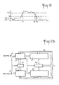
- Frame synchronization signals ST and line SL, a STP frame parity recognition signal and a black reference signal can be obtained using an analog processing device 2 such as that which has been represented in FIG. 10, from the composite video signals supplied by the cameras 11, 12.
- the shape of the composite video signals B is represented in FIG. 8 as a function of the numbers of lines 1 to 625 indicated on the scale A.
- An example of circuit 21 for extracting line synchronization signals SL has been represented in FIG. 10 and comprises a PNP transistor 213 which is saturated when the synchronization signals appear.
- the video signals are applied, via a link capacitor 210, to the base of transistor 213 which is biased by resistors 211, 212.
- the emitter of transistor 213 is connected to the power supply by the parallel circuit.
- the frame synchronization signal ST and a frame parity signal STP can be produced in a circuit such as the circuit 22 of FIG. 10 which recognizes the difference between the formats of synchronization of even and odd frame.
- a re-triggerable monostable circuit 220 For detection of the frame synchronization signal, a re-triggerable monostable circuit 220 is activated on each falling edge of the synchronization signal. If no new trigger is generated before 42 ms, i.e. 2/3 of the duration of a line, the monostable 220 returns to its stable state. On the other hand, and this is the case during synchro-frame, if the synchro-line signals are present in the middle of the line, there will be occurrence of the signal when the monostable has not returned to rest. This event will be stored in a flip-flop 221 of type D. The shape of the signals C and D at the output of circuits 220 and 221 is shown in FIG. 8.
- the frame parity recognition device works on the same principle.
- a monostable 222 whose duration is 8 lines is triggered.
- the monostable 222 returns to zero, the level of the frame synchronization signal is taken and stored in a flip-flop 223. This signal level is representative of the parity, a logic level 1 corresponding to an odd frame.
- the blanking signal present in the composite video signal defines the level of black n4. It allows you to get rid of the average brightness.
- the circuit composed of the elements 230 to 233 of FIG. 10 makes it possible to save the black reference voltage in an analog memory, the sampling duration being 5 ms.
- the black reference voltage is then removed from the luminance signal using a subtractor produced from an analog amplifier with a passband greater than 5 MHz consisting of an operational amplifier 244 and resistors 241, 242, 243 and 245.
- Two fast comparator circuits 246, 247 supply signals FM and FD corresponding to the crossing of thresholds SHI of level n1 and SB of level n2 during the increase and the decrease of the video signal (Fig 9).
- the threshold signals SHI and SB are programmed by the computer. They can be coded for example on 5 bits and converted by a digital-analog converter.
- An analog adder can add a voltage to the composite video signal from the camera, which makes it possible to view points on the control monitor whose luminance is above the FM threshold. This facilitates setting the thresholds.
- An essential characteristic of the processing device resides in the acquisition of singular points on the image, which singular points are constituted by light spots which have a certain surface to intercept several scanning lines and, of a frame to the other, are located in localized zones of the field of vision of the cameras.
- the search for light spots can therefore advantageously be limited to certain areas depending on the location of the spots in the previous frame.
- the recognition of light spots generally involves the acquisition of the image coordinates of the points whose luminance is greater than a threshold or corresponds to a particular shade. As soon as the amplitude of the luminance signal becomes greater than a rising threshold n1, the image coordinates (x, y) of the start of the light segment intercepted by the scanning are memorized. Counting of the length dx of the segment continues as long as the amplitude of the signal remains above a level H which is programmable and may be a little different from n1, for example slightly less than n1. The triplet of information (x, y, dx) describing the light spot is transmitted to the computer when the amplitude of the video signal becomes less than a second level n2 which is less than n1 and less than H.
- FIG. 11 shows the circuits for counting and memorizing the coordinates and the lengths of segments of the different light spots.
- the synchro-frame signal initializes the counter Y 311 to a value Yo recorded in a register 310, which constitutes a parameter depending on the standard of the camera.
- the counter 311 is then incremented at each synchro-line.
- the zero crossing of the counter 311 indicates that the scanned line is the first line carrying information (insofar as there is rejection of the synchro-frame lines).
- a counter X 321 is initialized at the value Xo entered in a register 320, when the synchro-line signal appears.
- the counter 321 is incremented by a clock synchronized with the cameras.
- the value of Xo is chosen so that when the counter 321 goes to zero, the composite video signal contains a luminance signal.
- the contents of the counters 311 and 321 are stored in the buffer registers 312, 322 as soon as the FM signal appears.
- This FM signal also validates the counting of a length segment dx for the counter 331 which is incremented and whose content is transferred to the buffer register 332 on the appearance of the signal FD if dx is greater than or equal to a reference length.
- the storage circuits 312, 322, 332 delivering their information on a single bus 6 through three-state circuits 313, 323, 333.
- a counter 42, 43 for noise rejection is validated and incremented at the clock frequency. This device inhibits transfers if the segment length is less than a certain configured length. If the particle is validated when the FD signal appears, the contents of the temporary registers 312, 322, 332 corresponding to the counters 311, 321, 331 are transferred to a FIFO (first in first out) type stack located on the interface card 4 by multiplexing.
- FIFO first in first out
- An inhibition system 45 initialized by the computer 5 makes it possible to inhibit the acquisitions of particles for a variable duration after the acquisition of a light segment.
- the muting circuit 45 is thus connected to an input of an AND gate of which one of the inputs receives the FM signal and a third input receives a signal from a transfer sequencer 47.
- the control logic is implemented so to inhibit transfers if the luminance detection (active FM) takes place before the counting on line has started (x ⁇ o). It proceeds identically if FD appears while the luminance information has disappeared at the end of the line. This procedure ensures the rejection of particles located astride the borders of the observed area.
- the circuits 44 and 46 represent flip-flops.
- the present invention is applicable to the guidance of models or other floating devices, such as the boat 1 in FIG. 14 seen from above by two cameras 11, 12 and comprising four light spots 71 to 74.
- the device 91 for measuring the movements of the mock-up 1 also calculates in real time the lowering speed and develops, within a servo chain 92, the necessary command concerning the rudder angle which is to be adjusted. (fig 15).
- the measured values of the parameters x (cavally), y (swerve) and ⁇ (heading) defining the trajectory of the floating structure are trimmed at the level of the subtractor 93 at setpoint values Xo, Yo, ⁇ o.
- the error signals are then applied to a servo chain 94 of the PID type which in particular delivers a signal representative of the rudder angle which will be sent by a serial link to the control member.
- the video cameras 11, 12 can be moved in a known direction relative to the fixed marker OXYZ.
- Programs first ensure dialogue with the measurement system. These include, for example: - the INIT procedure: it makes it possible to communicate to the measurement system the value of the thresholds which condition the acquisition of the light segments. - the ACQ procedure: it acquires and sorts the light segments, calculates the barycenter of the particles.
- Programs also process the raw data of the acquisition: These include programs performing the calculation of three-dimensional coordinates from image coordinates and calibration coefficients, and the calculation of restitution of the attitude angles (roll, pitch, yaw) of the model.
- the AC program for the acquisition of light spots written in the Pascal language manages the sequence of acquisition of light points. It calls procedures written in Assembler which allow dialogue with the hardware interface.
- the operator must adjust the threshold so as to see on the screen of the control monitor only the light spots placed on the model (INIT procedure).
- the actual acquisition (ACQ procedure) is then triggered; it stops when npt particles are acquired. (This total volume of information is provided by the operator).
- the data is in the central memory of the computer; the program makes it possible to read these results, to carry out additional calculations, and to save the useful information in the form of a frame number (ntr), a number of particles in this frame (np), and image coordinates (xg, yg) in two files f_acq1 and f_acq2 each assigned to a camera.
- the function for adjusting the thresholding conditions is carried out in the initialization procedure INIT written in Assembler and called by the previously defined acquisition management program (AC) (step 52 of FIG. 3).
- the operator has the possibility of choosing the luminance level n1 from which the acquisition of a light segment can be triggered. This value, between 0 and 64, depends on the ambient lighting conditions and the aperture of the lens.
- the ACQ procedure for acquiring the light segments should only be called when the thresholds are correctly set (in the INIT procedure). It reads at the interface level the two words containing information on the initial coordinates of the light segment, its length, and the camera number.
- the software constantly scans the interface, to find out whether or not there is a particle present.
- the program is oriented towards the calculation of the barycenter of a particle acquired at the earliest during the previous frame, this to avoid calculations being carried out on spots which do not are not yet fully defined.
- This program saves the useful information in the computer's main memory.
- Each 128 KB of memory makes it possible to store the data relating to 2000 consecutive frames containing three particles.
- the corresponding acquisition time at 60 Hz is around 35 s.
- the calculation of the 3D coordinates representing the movements of the structure itself consists in the simple resolution of a system of four linear equations with three unknowns, from image coordinates and calibration coefficients, when the device uses two cameras observing in stereo vision a structure carrying four light spots.
Landscapes
- Chemical & Material Sciences (AREA)
- Engineering & Computer Science (AREA)
- Combustion & Propulsion (AREA)
- Mechanical Engineering (AREA)
- Ocean & Marine Engineering (AREA)
- Physics & Mathematics (AREA)
- General Physics & Mathematics (AREA)
- Length Measuring Devices By Optical Means (AREA)
- Length Measuring Devices With Unspecified Measuring Means (AREA)
- Testing Or Calibration Of Command Recording Devices (AREA)
Applications Claiming Priority (2)
| Application Number | Priority Date | Filing Date | Title |
|---|---|---|---|
| FR8614567A FR2605401B1 (fr) | 1986-10-20 | 1986-10-20 | Procede et dispositif optoelectronique de mesure en temps reel de mouvements d'une structure solide soumise a l'effet d'un fluide |
| FR8614567 | 1986-10-20 |
Publications (2)
| Publication Number | Publication Date |
|---|---|
| EP0268509A1 true EP0268509A1 (de) | 1988-05-25 |
| EP0268509B1 EP0268509B1 (de) | 1990-06-27 |
Family
ID=9340004
Family Applications (1)
| Application Number | Title | Priority Date | Filing Date |
|---|---|---|---|
| EP87402308A Expired - Lifetime EP0268509B1 (de) | 1986-10-20 | 1987-10-16 | Optoelektronisches Verfahren und Gerät zur Echtzeitmessung der Bewegungen eines unter Flüssigkeitseinfluss stehenden Festkörpers |
Country Status (6)
| Country | Link |
|---|---|
| US (1) | US4843460A (de) |
| EP (1) | EP0268509B1 (de) |
| DE (1) | DE3763457D1 (de) |
| DK (1) | DK544687A (de) |
| FR (1) | FR2605401B1 (de) |
| NO (1) | NO170042C (de) |
Cited By (8)
| Publication number | Priority date | Publication date | Assignee | Title |
|---|---|---|---|---|
| EP0330100A3 (en) * | 1988-02-23 | 1990-11-22 | Ullrich Dipl.-Ing. Thiedig | Optical measuring device |
| EP0446903A3 (en) * | 1990-03-15 | 1992-09-30 | Honda Giken Kogyo Kabushiki Kaisha | Automatic travelling apparatus |
| NL1001778C2 (nl) * | 1995-11-03 | 1997-05-13 | Allseas Group Sa | Werkwijze en inrichting voor het verwijderen van een opbouw. |
| EP0803703A1 (de) * | 1996-04-23 | 1997-10-29 | Snap-on Equipment Srl a unico socio. | Verfahren zur Bestimmung der Fahrzeugradausrichtung |
| CN106289723A (zh) * | 2016-09-13 | 2017-01-04 | 江苏科技大学 | 一种船模横倾远程试验系统及试验方法 |
| CN106428419A (zh) * | 2016-09-13 | 2017-02-22 | 江苏科技大学 | 一种船模横摇衰减远程试验系统及试验方法 |
| CN107941458A (zh) * | 2017-12-13 | 2018-04-20 | 中国特种飞行器研究所 | 一种气垫式地效翼船模型水池拖曳试验方法 |
| CN108362473A (zh) * | 2017-12-13 | 2018-08-03 | 中国特种飞行器研究所 | 一种水面飞行器抗浪能力的单船身模型水池试验方法 |
Families Citing this family (11)
| Publication number | Priority date | Publication date | Assignee | Title |
|---|---|---|---|---|
| US4932541A (en) * | 1989-04-24 | 1990-06-12 | Calspan Corporation | Stabilized shipboard crane |
| DE4091054T (de) * | 1989-06-07 | 1992-04-23 | ||
| US5072294A (en) * | 1989-06-07 | 1991-12-10 | Loredan Biomedical, Inc. | Method and apparatus for analyzing a body having a marker located thereon |
| US5340309A (en) * | 1990-09-06 | 1994-08-23 | Robertson James G | Apparatus and method for recording jaw motion |
| US7907150B2 (en) * | 2003-08-09 | 2011-03-15 | Doubleshot, Inc. | Method of fusion or merging imagery data for improved visual perception using monoscopic and stereographic fusion and retinal decay techniques |
| US8538734B2 (en) * | 2004-01-21 | 2013-09-17 | California Institute Of Technology | Extreme event performance evaluation using real-time hysteresis monitoring |
| CN101788266B (zh) * | 2007-06-22 | 2012-12-12 | 上海海事大学 | 一种散货自动化装船检测装置检测船倾角度(横向)的方法 |
| CN104236455B (zh) * | 2014-06-13 | 2016-09-07 | 苏州西博三维科技有限公司 | 蜂巢板在线检测系统及其检测方法 |
| US11087644B2 (en) | 2015-08-19 | 2021-08-10 | E Ink Corporation | Displays intended for use in architectural applications |
| EP3226095A1 (de) | 2016-03-31 | 2017-10-04 | Fraunhofer-Gesellschaft zur Förderung der angewandten Forschung e.V. | System und verfahren zur navigation eines autonom navigierenden tauchkörpers beim einfahren in eine fangstation |
| PT3465628T (pt) * | 2016-05-24 | 2020-07-24 | E Ink Corp | Método para reprodução de imagens de cor |
Citations (5)
| Publication number | Priority date | Publication date | Assignee | Title |
|---|---|---|---|---|
| FR2147250A1 (de) * | 1971-07-27 | 1973-03-09 | Atmospheric Sciences Inc | |
| DE2947347A1 (de) * | 1979-11-23 | 1981-05-27 | Linde Ag, 6200 Wiesbaden | Rektifikationseinrichtung fuer eine um eine nullage schwankende anlage |
| BE893699A (fr) * | 1981-06-29 | 1982-12-29 | Westinghouse Electric Corp | Appareil detecteur de proximite visuel sans contact |
| FR2511917A1 (fr) * | 1981-08-28 | 1983-03-04 | Stanford Res Inst Int | Procede et appareil de commande du positionnement d'un outil par rapport a une piece |
| DE3428983A1 (de) * | 1983-08-31 | 1985-03-21 | SINCON S.p.A. Sistemi Informativi e di Controllo, Rom | Verfahren und geraet zum feststellen der position von gegenstaenden im raum |
Family Cites Families (3)
| Publication number | Priority date | Publication date | Assignee | Title |
|---|---|---|---|---|
| US4123017A (en) * | 1970-11-09 | 1978-10-31 | Martin Marietta Corporation | Dual, non-crossing horizontal gate tracking circuit and method |
| US4549211A (en) * | 1983-03-31 | 1985-10-22 | Hughes Aircraft Company | Four-quadrant gate-sizing technique |
| US4706119A (en) * | 1985-09-11 | 1987-11-10 | Shell Offshore Inc. | Camera vision axis inclination indication apparatus |
-
1986
- 1986-10-20 FR FR8614567A patent/FR2605401B1/fr not_active Expired - Lifetime
-
1987
- 1987-10-14 US US07/111,497 patent/US4843460A/en not_active Expired - Fee Related
- 1987-10-16 EP EP87402308A patent/EP0268509B1/de not_active Expired - Lifetime
- 1987-10-16 DE DE8787402308T patent/DE3763457D1/de not_active Expired - Lifetime
- 1987-10-19 NO NO874354A patent/NO170042C/no unknown
- 1987-10-19 DK DK544687A patent/DK544687A/da not_active Application Discontinuation
Patent Citations (5)
| Publication number | Priority date | Publication date | Assignee | Title |
|---|---|---|---|---|
| FR2147250A1 (de) * | 1971-07-27 | 1973-03-09 | Atmospheric Sciences Inc | |
| DE2947347A1 (de) * | 1979-11-23 | 1981-05-27 | Linde Ag, 6200 Wiesbaden | Rektifikationseinrichtung fuer eine um eine nullage schwankende anlage |
| BE893699A (fr) * | 1981-06-29 | 1982-12-29 | Westinghouse Electric Corp | Appareil detecteur de proximite visuel sans contact |
| FR2511917A1 (fr) * | 1981-08-28 | 1983-03-04 | Stanford Res Inst Int | Procede et appareil de commande du positionnement d'un outil par rapport a une piece |
| DE3428983A1 (de) * | 1983-08-31 | 1985-03-21 | SINCON S.p.A. Sistemi Informativi e di Controllo, Rom | Verfahren und geraet zum feststellen der position von gegenstaenden im raum |
Cited By (11)
| Publication number | Priority date | Publication date | Assignee | Title |
|---|---|---|---|---|
| EP0330100A3 (en) * | 1988-02-23 | 1990-11-22 | Ullrich Dipl.-Ing. Thiedig | Optical measuring device |
| EP0446903A3 (en) * | 1990-03-15 | 1992-09-30 | Honda Giken Kogyo Kabushiki Kaisha | Automatic travelling apparatus |
| NL1001778C2 (nl) * | 1995-11-03 | 1997-05-13 | Allseas Group Sa | Werkwijze en inrichting voor het verwijderen van een opbouw. |
| EP0803703A1 (de) * | 1996-04-23 | 1997-10-29 | Snap-on Equipment Srl a unico socio. | Verfahren zur Bestimmung der Fahrzeugradausrichtung |
| US5724129A (en) * | 1996-04-23 | 1998-03-03 | G.S. S.R.L. | Method for determining vehicle wheel alignments |
| CN106289723A (zh) * | 2016-09-13 | 2017-01-04 | 江苏科技大学 | 一种船模横倾远程试验系统及试验方法 |
| CN106428419A (zh) * | 2016-09-13 | 2017-02-22 | 江苏科技大学 | 一种船模横摇衰减远程试验系统及试验方法 |
| CN106428419B (zh) * | 2016-09-13 | 2018-05-22 | 江苏科技大学 | 一种船模横摇衰减远程试验系统及试验方法 |
| CN107941458A (zh) * | 2017-12-13 | 2018-04-20 | 中国特种飞行器研究所 | 一种气垫式地效翼船模型水池拖曳试验方法 |
| CN108362473A (zh) * | 2017-12-13 | 2018-08-03 | 中国特种飞行器研究所 | 一种水面飞行器抗浪能力的单船身模型水池试验方法 |
| CN107941458B (zh) * | 2017-12-13 | 2019-08-02 | 中国特种飞行器研究所 | 一种气垫式地效翼船模型水池拖曳试验方法 |
Also Published As
| Publication number | Publication date |
|---|---|
| FR2605401A1 (fr) | 1988-04-22 |
| DK544687A (da) | 1988-04-21 |
| NO170042B (no) | 1992-05-25 |
| DK544687D0 (da) | 1987-10-19 |
| NO874354L (no) | 1988-04-21 |
| DE3763457D1 (de) | 1990-08-02 |
| NO170042C (no) | 1992-09-02 |
| NO874354D0 (no) | 1987-10-19 |
| FR2605401B1 (fr) | 1992-04-17 |
| US4843460A (en) | 1989-06-27 |
| EP0268509B1 (de) | 1990-06-27 |
Similar Documents
| Publication | Publication Date | Title |
|---|---|---|
| EP0268509B1 (de) | Optoelektronisches Verfahren und Gerät zur Echtzeitmessung der Bewegungen eines unter Flüssigkeitseinfluss stehenden Festkörpers | |
| EP1462992B1 (de) | Anordnung und Verfahren zur Gestaltrekonstruktion aus optischen Bildern | |
| FR2656684A1 (fr) | Systeme d'inspection des munitions des armes portatives. | |
| FR2485785A1 (fr) | Memoire numerique a semi-conducteur a acces libre, a grande vitesse | |
| FR2751067A1 (fr) | Systeme et sous-systeme de determination de l'attitude d'une camera a l'interieur d'un objet | |
| US20170108332A1 (en) | Motion Contrast Depth Scanning | |
| EP3072108A1 (de) | Verfahren zur schätzung der geschwindigkeit einer kamerabewegung | |
| KR20000071087A (ko) | 옥외용 거리 계측 장치 | |
| EP3827320B1 (de) | Motorisiertes luftfahrzeug zum messen des reliefs von oberflächen eines vorbestimmten objekts und verfahren zur steuerung eines solchen luftfahrzeugs | |
| EP0435768B1 (de) | Verfahren und Anordnung zur Lagebestimmung eines bewegten Körpers durch Verfolgen einer auf dem Körper angeordneten Markierung | |
| Haussmann et al. | Streak detection of space debris by a passive optical sensor | |
| FR2519138A1 (fr) | Procede et appareil automatique pour la numerisation d'une surface tridimensionnelle | |
| EP0608945B1 (de) | Sterndetektor mit ladungsgekoppelter Matrix, Verfahren zur Detektion und Anwendung zur Neueinstellung eines Raumfahrzeuges | |
| FR2981149A1 (fr) | Aeronef comprenant un senseur optique diurne et nocturne, et procede de mesure d'attitude associe | |
| EP0385528B1 (de) | Verfahren und System zur Bestimmung der Position und der relativen Lage zweier Objekte im Raum | |
| FR2570195A1 (fr) | Appareil de recherche de cibles optoelectronique permettant une saisie et determination automatique de l'objectif a bord de vehicules porteurs | |
| EP3073441A1 (de) | Verfahren zur korrektur eines bildes mindestens eines objekts, das vor einem bildanzeigegerät in der ferne dargestellt und von einem beleuchtungssystem beleuchtet wird, und bildaufnahmesystem für die umsetzung dieses verfahrens | |
| EP0604245B1 (de) | Verfahren zur Erscheinungsdetektierung von Punktgegenständen in einem Bild | |
| WO1993019376A1 (fr) | Procede et dispositif de mesure optique des dimensions ou de la vitesse d'un objet en mouvement dans un fluide | |
| EP3350581A1 (de) | Kalibrier- oder testmuster | |
| EP1095358B1 (de) | Verfahren zur modellierung von gegenständen oder dreidimensionalen szenen | |
| US8577638B1 (en) | Imaging system and associated methods | |
| Hanson | Event-Based Camera Simulation and Neural Network Processing For Autonomous Aerial Refueling | |
| CN121632958A (zh) | 一种零件连续自适应检测方法、设备、介质和产品 | |
| EP0575208A1 (de) | Verfahren zur Herstellung des Auftretens von Punktobjekten auf einem Texturierten Hintergrund |
Legal Events
| Date | Code | Title | Description |
|---|---|---|---|
| PUAI | Public reference made under article 153(3) epc to a published international application that has entered the european phase |
Free format text: ORIGINAL CODE: 0009012 |
|
| 17P | Request for examination filed |
Effective date: 19871026 |
|
| AK | Designated contracting states |
Kind code of ref document: A1 Designated state(s): DE GB IT NL SE |
|
| RAP1 | Party data changed (applicant data changed or rights of an application transferred) |
Owner name: ETAT-FRANCAIS REPRESENTE PAR LE DELEGUE GENERAL PO |
|
| 17Q | First examination report despatched |
Effective date: 19890928 |
|
| GRAA | (expected) grant |
Free format text: ORIGINAL CODE: 0009210 |
|
| AK | Designated contracting states |
Kind code of ref document: B1 Designated state(s): DE GB IT NL SE |
|
| REF | Corresponds to: |
Ref document number: 3763457 Country of ref document: DE Date of ref document: 19900802 |
|
| ITF | It: translation for a ep patent filed | ||
| GBT | Gb: translation of ep patent filed (gb section 77(6)(a)/1977) | ||
| PLBE | No opposition filed within time limit |
Free format text: ORIGINAL CODE: 0009261 |
|
| 26N | No opposition filed | ||
| ITTA | It: last paid annual fee | ||
| EAL | Se: european patent in force in sweden |
Ref document number: 87402308.8 |
|
| PGFP | Annual fee paid to national office [announced via postgrant information from national office to epo] |
Ref country code: SE Payment date: 19950925 Year of fee payment: 9 |
|
| PGFP | Annual fee paid to national office [announced via postgrant information from national office to epo] |
Ref country code: GB Payment date: 19951003 Year of fee payment: 9 |
|
| PGFP | Annual fee paid to national office [announced via postgrant information from national office to epo] |
Ref country code: NL Payment date: 19951031 Year of fee payment: 9 |
|
| PGFP | Annual fee paid to national office [announced via postgrant information from national office to epo] |
Ref country code: DE Payment date: 19951219 Year of fee payment: 9 |
|
| PG25 | Lapsed in a contracting state [announced via postgrant information from national office to epo] |
Ref country code: GB Effective date: 19961016 |
|
| PG25 | Lapsed in a contracting state [announced via postgrant information from national office to epo] |
Ref country code: SE Effective date: 19961017 |
|
| PG25 | Lapsed in a contracting state [announced via postgrant information from national office to epo] |
Ref country code: NL Effective date: 19970501 |
|
| GBPC | Gb: european patent ceased through non-payment of renewal fee |
Effective date: 19961016 |
|
| NLV4 | Nl: lapsed or anulled due to non-payment of the annual fee |
Effective date: 19970501 |
|
| PG25 | Lapsed in a contracting state [announced via postgrant information from national office to epo] |
Ref country code: DE Effective date: 19970701 |
|
| EUG | Se: european patent has lapsed |
Ref document number: 87402308.8 |
|
| PG25 | Lapsed in a contracting state [announced via postgrant information from national office to epo] |
Ref country code: IT Free format text: LAPSE BECAUSE OF NON-PAYMENT OF DUE FEES;WARNING: LAPSES OF ITALIAN PATENTS WITH EFFECTIVE DATE BEFORE 2007 MAY HAVE OCCURRED AT ANY TIME BEFORE 2007. THE CORRECT EFFECTIVE DATE MAY BE DIFFERENT FROM THE ONE RECORDED. Effective date: 20051016 |