EP3828026B1 - Befestigungsvorrichtung für fahrzeugsitz - Google Patents
Befestigungsvorrichtung für fahrzeugsitz Download PDFInfo
- Publication number
- EP3828026B1 EP3828026B1 EP20209468.6A EP20209468A EP3828026B1 EP 3828026 B1 EP3828026 B1 EP 3828026B1 EP 20209468 A EP20209468 A EP 20209468A EP 3828026 B1 EP3828026 B1 EP 3828026B1
- Authority
- EP
- European Patent Office
- Prior art keywords
- rail
- fixing
- seat
- longitudinal
- floor
- Prior art date
- Legal status (The legal status is an assumption and is not a legal conclusion. Google has not performed a legal analysis and makes no representation as to the accuracy of the status listed.)
- Active
Links
Images


Classifications
-
- B—PERFORMING OPERATIONS; TRANSPORTING
- B60—VEHICLES IN GENERAL
- B60N—SEATS SPECIALLY ADAPTED FOR VEHICLES; VEHICLE PASSENGER ACCOMMODATION NOT OTHERWISE PROVIDED FOR
- B60N2/00—Seats specially adapted for vehicles; Arrangement or mounting of seats in vehicles
- B60N2/005—Arrangement or mounting of seats in vehicles, e.g. dismountable auxiliary seats
-
- B—PERFORMING OPERATIONS; TRANSPORTING
- B60—VEHICLES IN GENERAL
- B60N—SEATS SPECIALLY ADAPTED FOR VEHICLES; VEHICLE PASSENGER ACCOMMODATION NOT OTHERWISE PROVIDED FOR
- B60N2/00—Seats specially adapted for vehicles; Arrangement or mounting of seats in vehicles
- B60N2/005—Arrangement or mounting of seats in vehicles, e.g. dismountable auxiliary seats
- B60N2/015—Attaching seats directly to vehicle chassis
- B60N2/01508—Attaching seats directly to vehicle chassis using quick release attachments
- B60N2/01516—Attaching seats directly to vehicle chassis using quick release attachments with locking mechanisms
-
- B—PERFORMING OPERATIONS; TRANSPORTING
- B60—VEHICLES IN GENERAL
- B60N—SEATS SPECIALLY ADAPTED FOR VEHICLES; VEHICLE PASSENGER ACCOMMODATION NOT OTHERWISE PROVIDED FOR
- B60N2/00—Seats specially adapted for vehicles; Arrangement or mounting of seats in vehicles
- B60N2/02—Seats specially adapted for vehicles; Arrangement or mounting of seats in vehicles the seat or part thereof being movable, e.g. adjustable
- B60N2/04—Seats specially adapted for vehicles; Arrangement or mounting of seats in vehicles the seat or part thereof being movable, e.g. adjustable the whole seat being movable
- B60N2/06—Seats specially adapted for vehicles; Arrangement or mounting of seats in vehicles the seat or part thereof being movable, e.g. adjustable the whole seat being movable slidable
- B60N2/07—Slide construction
-
- B—PERFORMING OPERATIONS; TRANSPORTING
- B60—VEHICLES IN GENERAL
- B60N—SEATS SPECIALLY ADAPTED FOR VEHICLES; VEHICLE PASSENGER ACCOMMODATION NOT OTHERWISE PROVIDED FOR
- B60N2/00—Seats specially adapted for vehicles; Arrangement or mounting of seats in vehicles
- B60N2/02—Seats specially adapted for vehicles; Arrangement or mounting of seats in vehicles the seat or part thereof being movable, e.g. adjustable
- B60N2/04—Seats specially adapted for vehicles; Arrangement or mounting of seats in vehicles the seat or part thereof being movable, e.g. adjustable the whole seat being movable
- B60N2/06—Seats specially adapted for vehicles; Arrangement or mounting of seats in vehicles the seat or part thereof being movable, e.g. adjustable the whole seat being movable slidable
- B60N2/07—Slide construction
- B60N2/0722—Constructive details
- B60N2/0732—Attachment of seat frame to the slide, e.g. eyelets
-
- B—PERFORMING OPERATIONS; TRANSPORTING
- B60—VEHICLES IN GENERAL
- B60N—SEATS SPECIALLY ADAPTED FOR VEHICLES; VEHICLE PASSENGER ACCOMMODATION NOT OTHERWISE PROVIDED FOR
- B60N2/00—Seats specially adapted for vehicles; Arrangement or mounting of seats in vehicles
- B60N2/02—Seats specially adapted for vehicles; Arrangement or mounting of seats in vehicles the seat or part thereof being movable, e.g. adjustable
- B60N2/04—Seats specially adapted for vehicles; Arrangement or mounting of seats in vehicles the seat or part thereof being movable, e.g. adjustable the whole seat being movable
- B60N2/06—Seats specially adapted for vehicles; Arrangement or mounting of seats in vehicles the seat or part thereof being movable, e.g. adjustable the whole seat being movable slidable
- B60N2/08—Seats specially adapted for vehicles; Arrangement or mounting of seats in vehicles the seat or part thereof being movable, e.g. adjustable the whole seat being movable slidable characterised by the locking device
-
- B—PERFORMING OPERATIONS; TRANSPORTING
- B60—VEHICLES IN GENERAL
- B60N—SEATS SPECIALLY ADAPTED FOR VEHICLES; VEHICLE PASSENGER ACCOMMODATION NOT OTHERWISE PROVIDED FOR
- B60N2/00—Seats specially adapted for vehicles; Arrangement or mounting of seats in vehicles
- B60N2/24—Seats specially adapted for vehicles; Arrangement or mounting of seats in vehicles for particular purposes or particular vehicles
- B60N2/242—Bus seats
-
- B—PERFORMING OPERATIONS; TRANSPORTING
- B61—RAILWAYS
- B61D—BODY DETAILS OR KINDS OF RAILWAY VEHICLES
- B61D33/00—Seats
- B61D33/0057—Seats characterised by their mounting in vehicles
- B61D33/0078—Seats characterised by their mounting in vehicles adjustably mounted
Definitions
- the present invention relates to a device for fixing a vehicle seat to a floor of this vehicle.
- the invention is particularly suitable for a railway vehicle, but could be used for any type of vehicle, in particular a public transport vehicle (bus, marine vehicle, plane) or any vehicle whose seats are fixed to a floor (car, etc.). .).
- the seats in a passenger room can usually be arranged in two configurations, namely a first class configuration (in which the seats are relatively wide and spaced apart from each other) and a second class configuration (in which the seats are narrower and closer together).
- passenger lounges have an identical structure for first class or second class configurations.
- the positions of first class seats differ from the positions of second class seats, but the means of securing the seats to the floor must be the same for both configurations.
- a seat fixing device comprising a rail fixed to the floor of the vehicle. It is then possible to fix the seats at different possible positions on the rail, allowing the spacing between the seats to be modulated according to the desired configuration.
- Such a rail has various disadvantages. For example, it is necessary to add a rail masking element, covering this rail. However, such a masking element generally protrudes above the level of the floor, and can thus be a source of discomfort for passengers, reduce the aesthetics of the floor, and/or hinder the passage of maintenance devices (such as vacuum cleaners). ).
- Another seat fixing device is for example described in US 9,975,454 .
- the invention aims in particular to remedy the aforementioned drawbacks, by providing a seat fixing device not comprising a floor rail, without reducing the modularity of the fixing.
- the invention relates in particular to a seat fixing device according to claim 1.
- the longitudinal fixing member it remains possible to arrange the seat in a desired position in a continuous interval around the insert.
- the invention therefore allows great modularity in the positioning of the seat, without requiring a rail on the floor, but only at least one specific insert per seat.
- the invention also relates to a vehicle seat, in particular a railway vehicle, comprising an upright intended to be fixed to a floor of the vehicle, characterized in that the upright is provided with a fixing device as defined above.
- the invention also relates to a vehicle, in particular a railway vehicle, comprising a floor, characterized in that the floor comprises at least one insert, the vehicle comprising at least one seat as defined above, fixed to the floor by means of the 'insert.
- a seat 10 for a vehicle intended to be fixed to a floor 12 of this vehicle.
- the vehicle is for example a railway vehicle, but it could alternatively be any type of vehicle whose seats are fixed to the floor, in particular any type of public transport vehicle (bus, plane, marine vehicle, etc.) or private vehicle (car, truck, etc.).
- the floor 12 comprises at least one point insert 14, and preferably a plurality of point inserts 14 aligned in a longitudinal direction X.
- Each insert 14 is for example formed by a hollow cylinder, preferably a hollow cylinder whose interior is threaded.
- Each insert 14 is capable of receiving a complementary fixing element 16, for example a screw, a bolt, a rivet or any other suitable fixing element.
- the seat 10 comprises at least one upright 18, extending in a direction comprising a vertical component, from the floor 12, and carrying at least one seat element 20.
- the seat 10 can be a seat with double seat elements 20, the seat elements 20 being secured to one another, one next to the other.
- a seat with double seat elements generally comprises two uprights 18. However, only one upright 18 will be described below, the other upright being similar.
- the present invention relates more particularly to a device 22 for fixing the seat to the floor 12.
- This fixing device 22 is generally carried by the upright 18.
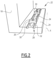
- a fixing device 22 according to a first exemplary embodiment is shown on the figure 2 .
- the fixing device 22 comprises a longitudinal fixing member 24, integral with the upright 18, for example fixed to this upright 18 or, in the example described in accordance with this first embodiment, integral with this upright 18.
- the longitudinal fixing member 24 extends in a longitudinal direction X, which is generally the direction in which the vehicle extends in length.
- the longitudinal fixing member 24 comprises at least one passage orifice 26 intended to be crossed by a respective one of the fixing elements 16.
- the longitudinal fixing member 24 is shaped to receive the fixing element 16 in a plurality of possible positions in the longitudinal direction X relative to the upright 18 of the seat, the plurality of possible positions forming a segment continuous extending in the longitudinal direction Simply place the seat post 18 in the desired position, and make the passage hole 26 coincide with the insert 14 to allow fixing.
- the longitudinal fixing member 24 comprises a rail 28 extending in the longitudinal direction at least one passage orifice 26.
- the rail 28 is formed by at least one groove 32, preferably two grooves 32 parallel to each other.
- each mobile element 30 has a section transverse in the general shape of a U, comprising two branches each cooperating with a respective one of the grooves 32, and a central part comprising the passage orifice 26.
- the longitudinal fixing member 24 is formed by a foot of the upright 18, this foot extending parallel to the floor 12, so that each passage orifice 26 can be arranged facing each other. of one of the corresponding inserts 14.
- this longitudinal fixing member 24 comprises an oblong passage opening 34, extending parallel to the rail 28, the passage orifice 26 of each movable element 30 being arranged opposite the oblong passage opening 34.
- each fixing element 16 can pass both through the corresponding passage orifice 26 and through the oblong passage opening 34 to reach the corresponding insert 14.
- the rail 28 has a length substantially equal to that of the oblong opening 34 in the longitudinal direction, or is slightly shorter or longer, so that, whatever the position of the movable element 30 on the rail 28, its passage orifice 26 faces the oblong opening 34.
- the oblong passage opening 34 extends between the grooves 32 of the rail 28.
- the longitudinal fixing member 24 would only include the oblong passage opening 34 (and would therefore be devoid of rail 28 and movable elements 30).
- this oblong passage opening 34 fulfills the function of passage orifice, the fixing elements 16 cooperating with the edges of this oblong passage opening 34.
- the use of the movable elements 30 to receive the elements of fixing 16 allows a more robust and more reliable fixing than a fixing with a simple oblong passage opening.
- the inserts 14 are previously inserted into the floor 12, at predefined locations.
- the seats can generally be arranged in two possible configurations, called first class (in which the seats are relatively wide and spaced from each other) or second class (in which the seats are more narrow and close together).
- Each insert 14 is then placed in the floor 12, in a location allowing both its attachment to a first class seat or to a second class seat, depending on the configuration chosen.
- the floor 12 can be equipped with a first set of first inserts 14, and a second set of second inserts 14, the vehicle comprising a plurality of seats, arranged in a first configuration by being fixed to the first inserts, or according to a second configuration by being attached to the second inserts.
- the seat 10 is brought to a chosen position, depending on the configuration (first or second class) chosen. In this chosen position, the oblong opening 34 faces the insert 14.
- this oblong opening 34 defines the continuous segment formed by the plurality of possible positions between the seat 10 and the insert 14: the seat 10 can be arranged in any position as long as the oblong opening 34 is in position. view of insert 14.
- the movable element 30 is arranged on the rail 28 to arrange its passage orifice 26 facing the insert 14.
- the rail 28 being continuous, the movable element 30 can be arranged at any position along this rail 28.
- the fixing element 16 is then passed through the passage orifice 26 and the oblong opening 34 to reach the insert 14 to which it is fixed, for example by screwing.
- the longitudinal member 24 is thus firmly fixed to the insert 14.
- a second insert 14 is also opposite the oblong opening 34, so that the fixing device 22 is also fixed there by means of a second movable element 30.
- a fixing device 22 according to a second exemplary embodiment is shown on the Figure 3 .
- elements similar to those in the previous figures are designated by identical references.
- a rail 28' is provided in the upright 18, near a lower end of the upright 18. This rail 28' extends in the longitudinal direction side of the upright 18. The rail 28' forms a T-shaped groove.
- the fixing device 22 comprises a longitudinal fixing member 24' in two parts, namely a first guide part 24a' cooperating with the rail 28' and movable along this rail 28', and a second fixing part 24b' integral with the first guide part 24a' and comprising at least one passage orifice 26.
- the first guide part 24a' is arranged in the rail 28', and it is movable along this rail 28'.
- the first guide part 24a' has for example a T-shaped cross section, substantially complementary to the shape of the rail 28', the lateral branches of which cooperate with edges of the rail 28' to maintain the first guide part 24a' in the rail 28', and the central branch of which extends outside the rail 28', between the edges of the rail 28'.
- the fixing device comprises means for locking the first guide part 24a' in a longitudinal position chosen along the rail 28'.
- These locking means can be of any conceivable type.
- the second fixing part 24b' is arranged outside the rail 28', being secured to the first guide part 24a', and more particularly to its central branch, to move with this first guide part 24a' along the rail.
- the first guide part 24a' comprises securing studs 36 cooperating with complementary orifices provided on the second fixing part 24b'. It should be noted, however, that any other means of solidarity is possible.
- the first 24a' and second 24b' parts could also alternatively have come from material.
- the second fixing part 24b' has an L-shaped cross section, defined by a vertical wall 38 secured to the first guide part 24a', and a horizontal wall 40 comprising at least one passage orifice 26, for example two passage orifices 26 spaced in the longitudinal direction X.
- the spacing between these two passage orifices 26 is the same as the spacing between two inserts 14 of the floor 12.
- the inserts 14 are, as described previously, previously inserted into the floor 12, at predefined locations.
- the seat 10 is arranged at a desired position, depending on the desired seating configuration (first or second class).
- the longitudinal member 24' is then slid along the rail 28' until the passage orifice(s) 26 coincide with the corresponding insert(s) 14. It then remains to fix the second fixing part 24b' to each insert 14, by means of a fixing element 16 passing through the corresponding passage orifice 26 and cooperating with the insert 14, for example by screwing.
- the rail 28' defines the continuous segment formed by the plurality of possible positions between the seat 10 and the insert 14: the seat 10 can be arranged in any position as long as the longitudinal member 24' can be slid in the rail until each passage orifice 26 faces the corresponding insert 14.
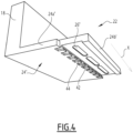
- a fixing device 22 according to a third exemplary embodiment is shown on the Figure 4 .
- elements similar to those in the previous figures are designated by identical references.
- the longitudinal fixing member 24" comprises a first part 24a" secured to the seat post 18, and a second part 24b" comprising at least one passage orifice 26".
- the first part 24a" is for example integral with the amount 18.
- the second part 24b" can be assembled with the first part 24a" in several possible positions.
- the first part 24a" comprises a first crenellated edge 42
- the second part 24b" comprises a second crenellated edge 44 complementary to the first crenellated edge 42, assemblable with this first crenellated edge 42 in a plurality of possible positions in the longitudinal direction
- crenellated edges 42, 44 also called combs
- crenellated edges 42, 44 only allows relative positions to be defined discretely (according to the crenellations) and not continuously.
- each passage orifice 26" has an elongated oblong shape in the longitudinal direction X.
- the second part 24b" has three orifices passage 26" oblong, but it could alternatively include only one over substantially its entire length, or two, or more, as long as all of the oblong passage orifices 26" extend over substantially the entire length of the second part 24b".
- the inserts 14 are, as described previously, previously inserted into the floor 12, at predefined locations.
- the seat 10 is arranged at a desired position, depending on the desired seat configuration (first or second class).
- the second part 26b" is then assembled to the first part 24a", so that one of the oblong passage orifices 26" is opposite a corresponding insert 14.
- the continuous segment formed by the plurality of possible positions between the seat 10 and the insert 14 is formed by the different relative positions of the first 24a" and second 24b" parts, in combination with the oblong shape of passage holes 26".
- the invention makes it possible to fix the seat 10 in a plurality of possible positions extending continuously along a segment, without requiring a rail arranged on the floor 12.
- the floor 12 does not does not require a rail concealment cover, so that the floor 12 does not have any projecting part.
Landscapes
- Engineering & Computer Science (AREA)
- Mechanical Engineering (AREA)
- Aviation & Aerospace Engineering (AREA)
- Transportation (AREA)
- Seats For Vehicles (AREA)
Claims (10)
- Vorrichtung (22) zur Befestigung eines Sitzes (10) eines Fahrzeugs, insbesondere eines Schienenfahrzeugs, auf einem Boden (12) des Fahrzeugs, umfassend:- mindestens einen Einsatz (14), der dazu bestimmt ist, in den Boden (12) eingesetzt zu werden, und mindestens ein Befestigungselement (16), das komplementär zu dem Einsatz (14) ist,- ein Längsbefestigungsorgan (24; 24'; 24"), das fest mit einer Säule (18) des Sitzes (10) verbunden ist, sich in einer Längsrichtung (X) erstreckt, umfassend mindestens eine Durchgangsöffnung (26; 26"), die dazu bestimmt ist, von einem jeweiligen des mindestens einen Befestigungselements (16) durchquert zu werden, wobei das Längsbefestigungsorgan (24; 24'; 24") geformt ist, um das Befestigungselement (16) an einer Vielzahl von möglichen Positionen in der Längsrichtung (X) in Bezug auf die Säule (18) des Sitzes (10) aufzunehmen, wobei die Vielzahl von möglichen Positionen ein durchgehendes Segment bildet, das sich in der Längsrichtung (X) erstreckt, dadurch gekennzeichnet, dass die Durchgangsöffnung (26, 26") an jeder möglichen Positionmit dem Einsatz (14) übereinstimmt, um eine Befestigung zu ermöglichen, wobei das Befestigungselement (16) die Durchgangsöffnung (26; 26") durchquert, um den Einsatz (14) zu erreichen und/oder damit zusammenzuwirken.
- Befestigungsvorrichtung (22) nach Anspruch 1, wobei das Längsbefestigungsorgan (24; 24') eine Schiene (28; 28'), die sich in der Längsrichtung (X) erstreckt, und mindestens ein Element (30; 24') umfasst, das entlang der Schiene beweglich ist, umfasst, wobei jedes bewegliche Element (30; 24') eine jeweilige der mindestens einen Durchgangsöffnung (26) umfasst.
- Befestigungsvorrichtung (22) nach Anspruch 2, bei der das Längsbefestigungsorgan (24) durch einen Fuß der Säule (18) des Sitzes (10) gebildet ist, wobei der Fuß dazu bestimmt ist sich parallel zu dem Boden zu erstrecken, und die Schiene (28) durch mindestens eine sich in der Längsrichtung (X) erstreckende Nut (32) gebildet ist, die an dem Fuß ausgebildet ist.
- Befestigungsvorrichtung (22) nach Anspruch 3, umfassend eine längliche Durchgangsöffnung (34), die sich parallel zu der Schiene (28) erstreckt, wobei die Durchgangsöffnung (26) von jedem beweglichen Element (30) gegenüber der länglichen Durchgangsöffnung (34) angeordnet ist, sodass jedes Befestigungselement (16) sowohl durch die entsprechende Durchgangsöffnung (26) als auch durch die längliche Durchgangsöffnung (34) verläuft.
- Befestigungsvorrichtung (22) nach Anspruch 3 oder 4, wobei die Schiene (28) zwei zueinander parallele Nuten (32) aufweist, wobei das bewegliche Element (30) einen allgemein U-förmigen Querschnitt aufweist, der zwei Schenkel, die jeweils mit einer entsprechenden der Nuten (32) zusammenwirken, und einen Mittelteil umfasst, der die Durchgangsöffnung (26) umfasst.
- Befestigungsvorrichtung (22) nach Anspruch 2, wobei die Schiene (28') in der Säule (18) des Sitzes (10) ausgebildet ist, das Längsbefestigungselement (24') einen ersten Führungsteil (24a'), der mit der Schiene (28') zusammenwirkt und entlang dieser Schiene (28') beweglich ist, und einen zweiten Befestigungsteil (24b') umfasst, der fest mit dem ersten Befestigungsteil (24a') verbunden ist, und umfassend die mindestens eine Durchgangsöffnung (26), wobei die Verriegelungsvorrichtung vorzugsweise Einrichtungen zum Verriegeln des ersten Führungsteils (24a') an einer ausgewählten Längsposition entlang der Schiene (28') umfasst.
- Befestigungsvorrichtung (22) nach Anspruch 1, bei der das Längsbefestigungsorgan (24") einen ersten Teil (24a"), der fest mit der Säule (18) des Sitzes verbunden ist, und einen zweiten Teil (24b") umfasst, der die mindestens eine Durchgangsöffnung (26") umfasst, wobei der zweite Teil (24b") in mehreren möglichen Positionen mit dem ersten Teil (24a") verbunden werden kann, wobei jede Durchgangsöffnung (26") vorzugsweise eine längliche Form aufweist, die in der Längsrichtung (X) verlängert ist.
- Befestigungsvorrichtung (22) nach Anspruch 7, wobei der erste Teil (24a") eine erste gezackte Kante (42) aufweist und der zweite Teil (24b") eine zweite gezackte Kante (44) aufweist, die komplementär zu der ersten gezackten Kante (42) ist und mit dieser ersten gezackten Kante (42) in einer Vielzahl von möglichen Positionen in der Längsrichtung (X) zusammengesetzt werden kann.
- Fahrzeugsitz (10), insbesondere eines Schienenfahrzeugs, umfassend eine Säule (18), die dazu bestimmt ist, an einem Boden (12) des Fahrzeugs befestigt zu werden, dadurch gekennzeichnet, dass die Säule (18) mit einer Befestigungsvorrichtung (22) nach einem der Ansprüche 1 bis 8 versehen ist.
- Fahrzeug, insbesondere Schienenfahrzeug, umfassend einen Boden (12), dadurch gekennzeichnet, dass der Boden (12) mindestens einen Einsatz (14) umfasst, wobei das Fahrzeug mindestens einen Sitz (10) nach Anspruch 9 aufweist, der mittels des Einsatzes (14) an dem Boden (12) befestigt ist.
Applications Claiming Priority (1)
| Application Number | Priority Date | Filing Date | Title |
|---|---|---|---|
| FR1913229A FR3103419B1 (fr) | 2019-11-26 | 2019-11-26 | Dispositif de fixation de siège de véhicule |
Publications (2)
| Publication Number | Publication Date |
|---|---|
| EP3828026A1 EP3828026A1 (de) | 2021-06-02 |
| EP3828026B1 true EP3828026B1 (de) | 2023-09-13 |
Family
ID=70295221
Family Applications (1)
| Application Number | Title | Priority Date | Filing Date |
|---|---|---|---|
| EP20209468.6A Active EP3828026B1 (de) | 2019-11-26 | 2020-11-24 | Befestigungsvorrichtung für fahrzeugsitz |
Country Status (3)
| Country | Link |
|---|---|
| EP (1) | EP3828026B1 (de) |
| ES (1) | ES2964931T3 (de) |
| FR (1) | FR3103419B1 (de) |
Families Citing this family (1)
| Publication number | Priority date | Publication date | Assignee | Title |
|---|---|---|---|---|
| US11427109B1 (en) * | 2020-04-30 | 2022-08-30 | Adam J. Wurzer | Truck seat adapter |
Family Cites Families (3)
| Publication number | Priority date | Publication date | Assignee | Title |
|---|---|---|---|---|
| DE29712180U1 (de) * | 1997-07-10 | 1997-09-11 | Oettl, Heinrich, 81373 München | Vorrichtung zur schnellösbaren, verschiebbaren und schnell arretierbaren Befestigung eines Fahrzeugausrüstungsteiles, wie z.B. eines Sitzes |
| DE10150917C2 (de) * | 2001-10-18 | 2003-08-14 | Vogel Ind Gmbh | Vorrichtung zur Befestigung eines Fahrgastsitzes |
| RU2015135584A (ru) * | 2013-01-23 | 2017-03-02 | Зодиак Ситс Франс | Кинематическое устройство компактного сиденья |
-
2019
- 2019-11-26 FR FR1913229A patent/FR3103419B1/fr active Active
-
2020
- 2020-11-24 ES ES20209468T patent/ES2964931T3/es active Active
- 2020-11-24 EP EP20209468.6A patent/EP3828026B1/de active Active
Also Published As
| Publication number | Publication date |
|---|---|
| ES2964931T3 (es) | 2024-04-10 |
| FR3103419B1 (fr) | 2022-08-12 |
| EP3828026A1 (de) | 2021-06-02 |
| FR3103419A1 (fr) | 2021-05-28 |
Similar Documents
| Publication | Publication Date | Title |
|---|---|---|
| EP1305860A1 (de) | Haltekonsole für kabelkanal-elemente | |
| EP2115837B1 (de) | Vorrichtung zur befestigung einer garn-kabelbahn | |
| EP0961341A1 (de) | Befestigungseinrichtung für eine Antenne | |
| FR2802254A1 (fr) | Dispositif d'accrochage a rail | |
| FR3035428A3 (fr) | Systeme pour porte de douche, et porte de douche | |
| EP3828026B1 (de) | Befestigungsvorrichtung für fahrzeugsitz | |
| EP1047981B1 (de) | Schnellbefestigungsvorrichtung für eine armbanduhr | |
| FR3047260A1 (fr) | Garde-corps autoporte | |
| EP3839173B1 (de) | Vorrichtung zur befestigung einer pfette eines schutzgitters an einem vertikalen pfosten, und mit einer solchen vorrichtung ausgestatteter zaun | |
| FR2518192A1 (fr) | Dispositif d'assemblage de deux pieces, telles que deux profiles realises par exemple en alliage leger | |
| EP1607551A1 (de) | Befestigungselement für ein Zaungitter an einem Pfosten und mit einem solchen Element hergestellter Zaun | |
| FR2906439A1 (fr) | Chassis pour panier-siege de pecheur | |
| EP2792581B1 (de) | Abmontierbare Halterungsstruktur von Karosserieelementen eines Kraftfahrzeugs | |
| EP1445382B1 (de) | Schwenkbare Sperre | |
| EP0914532A1 (de) | Abdeckvorrichtung zum oberflächenschutz von schwimmbad, becken usw. | |
| EP1722111A1 (de) | Befestigungselement zur Befestigung eines Metallprofils auf einem Träger | |
| EP1388918A1 (de) | Stützkonsole für Kabelbahnen | |
| FR2897334A1 (fr) | Dispositif de fixation d'un reservoir de liquide de frein sur une poutre d'auvent d'un vehicule automobile | |
| EP4455438A1 (de) | Rolladenrohrhalter, schutzeinrichtung, insbesondere für rolladen, und entsprechendes montageverfahren | |
| FR2893957A1 (fr) | Dispositif de support pour un panneau de signalisation | |
| WO2024179823A1 (fr) | Système de rambarde | |
| FR3144828A1 (fr) | Système de rambarde | |
| EP1371806A2 (de) | Tragevorrichtung für Rolladen | |
| FR3103842A1 (fr) | Dispositif de fixation d'une lisse d'une grille barreaudee sur un poteau vertical et cloture equipee d’un tel dispositif | |
| FR2710703A1 (fr) | Pièce d'assemblage de profilés. |
Legal Events
| Date | Code | Title | Description |
|---|---|---|---|
| PUAI | Public reference made under article 153(3) epc to a published international application that has entered the european phase |
Free format text: ORIGINAL CODE: 0009012 |
|
| STAA | Information on the status of an ep patent application or granted ep patent |
Free format text: STATUS: THE APPLICATION HAS BEEN PUBLISHED |
|
| STAA | Information on the status of an ep patent application or granted ep patent |
Free format text: STATUS: REQUEST FOR EXAMINATION WAS MADE |
|
| AK | Designated contracting states |
Kind code of ref document: A1 Designated state(s): AL AT BE BG CH CY CZ DE DK EE ES FI FR GB GR HR HU IE IS IT LI LT LU LV MC MK MT NL NO PL PT RO RS SE SI SK SM TR |
|
| 17P | Request for examination filed |
Effective date: 20210517 |
|
| RBV | Designated contracting states (corrected) |
Designated state(s): AL AT BE BG CH CY CZ DE DK EE ES FI FR GB GR HR HU IE IS IT LI LT LU LV MC MK MT NL NO PL PT RO RS SE SI SK SM TR |
|
| STAA | Information on the status of an ep patent application or granted ep patent |
Free format text: STATUS: EXAMINATION IS IN PROGRESS |
|
| 17Q | First examination report despatched |
Effective date: 20220801 |
|
| GRAP | Despatch of communication of intention to grant a patent |
Free format text: ORIGINAL CODE: EPIDOSNIGR1 |
|
| STAA | Information on the status of an ep patent application or granted ep patent |
Free format text: STATUS: GRANT OF PATENT IS INTENDED |
|
| INTG | Intention to grant announced |
Effective date: 20230425 |
|
| GRAS | Grant fee paid |
Free format text: ORIGINAL CODE: EPIDOSNIGR3 |
|
| GRAA | (expected) grant |
Free format text: ORIGINAL CODE: 0009210 |
|
| STAA | Information on the status of an ep patent application or granted ep patent |
Free format text: STATUS: THE PATENT HAS BEEN GRANTED |
|
| AK | Designated contracting states |
Kind code of ref document: B1 Designated state(s): AL AT BE BG CH CY CZ DE DK EE ES FI FR GB GR HR HU IE IS IT LI LT LU LV MC MK MT NL NO PL PT RO RS SE SI SK SM TR |
|
| REG | Reference to a national code |
Ref country code: CH Ref legal event code: EP |
|
| REG | Reference to a national code |
Ref country code: DE Ref legal event code: R096 Ref document number: 602020017562 Country of ref document: DE |
|
| REG | Reference to a national code |
Ref country code: IE Ref legal event code: FG4D Free format text: LANGUAGE OF EP DOCUMENT: FRENCH |
|
| P01 | Opt-out of the competence of the unified patent court (upc) registered |
Effective date: 20231020 |
|
| REG | Reference to a national code |
Ref country code: LT Ref legal event code: MG9D |
|
| REG | Reference to a national code |
Ref country code: NL Ref legal event code: MP Effective date: 20230913 |
|
| PG25 | Lapsed in a contracting state [announced via postgrant information from national office to epo] |
Ref country code: GR Free format text: LAPSE BECAUSE OF FAILURE TO SUBMIT A TRANSLATION OF THE DESCRIPTION OR TO PAY THE FEE WITHIN THE PRESCRIBED TIME-LIMIT Effective date: 20231214 |
|
| PG25 | Lapsed in a contracting state [announced via postgrant information from national office to epo] |
Ref country code: SE Free format text: LAPSE BECAUSE OF FAILURE TO SUBMIT A TRANSLATION OF THE DESCRIPTION OR TO PAY THE FEE WITHIN THE PRESCRIBED TIME-LIMIT Effective date: 20230913 Ref country code: RS Free format text: LAPSE BECAUSE OF FAILURE TO SUBMIT A TRANSLATION OF THE DESCRIPTION OR TO PAY THE FEE WITHIN THE PRESCRIBED TIME-LIMIT Effective date: 20230913 Ref country code: NO Free format text: LAPSE BECAUSE OF FAILURE TO SUBMIT A TRANSLATION OF THE DESCRIPTION OR TO PAY THE FEE WITHIN THE PRESCRIBED TIME-LIMIT Effective date: 20231213 Ref country code: LV Free format text: LAPSE BECAUSE OF FAILURE TO SUBMIT A TRANSLATION OF THE DESCRIPTION OR TO PAY THE FEE WITHIN THE PRESCRIBED TIME-LIMIT Effective date: 20230913 Ref country code: LT Free format text: LAPSE BECAUSE OF FAILURE TO SUBMIT A TRANSLATION OF THE DESCRIPTION OR TO PAY THE FEE WITHIN THE PRESCRIBED TIME-LIMIT Effective date: 20230913 Ref country code: HR Free format text: LAPSE BECAUSE OF FAILURE TO SUBMIT A TRANSLATION OF THE DESCRIPTION OR TO PAY THE FEE WITHIN THE PRESCRIBED TIME-LIMIT Effective date: 20230913 Ref country code: GR Free format text: LAPSE BECAUSE OF FAILURE TO SUBMIT A TRANSLATION OF THE DESCRIPTION OR TO PAY THE FEE WITHIN THE PRESCRIBED TIME-LIMIT Effective date: 20231214 Ref country code: FI Free format text: LAPSE BECAUSE OF FAILURE TO SUBMIT A TRANSLATION OF THE DESCRIPTION OR TO PAY THE FEE WITHIN THE PRESCRIBED TIME-LIMIT Effective date: 20230913 |
|
| REG | Reference to a national code |
Ref country code: AT Ref legal event code: MK05 Ref document number: 1610938 Country of ref document: AT Kind code of ref document: T Effective date: 20230913 |
|
| PG25 | Lapsed in a contracting state [announced via postgrant information from national office to epo] |
Ref country code: NL Free format text: LAPSE BECAUSE OF FAILURE TO SUBMIT A TRANSLATION OF THE DESCRIPTION OR TO PAY THE FEE WITHIN THE PRESCRIBED TIME-LIMIT Effective date: 20230913 |
|
| PG25 | Lapsed in a contracting state [announced via postgrant information from national office to epo] |
Ref country code: IS Free format text: LAPSE BECAUSE OF FAILURE TO SUBMIT A TRANSLATION OF THE DESCRIPTION OR TO PAY THE FEE WITHIN THE PRESCRIBED TIME-LIMIT Effective date: 20240113 |
|
| REG | Reference to a national code |
Ref country code: ES Ref legal event code: FG2A Ref document number: 2964931 Country of ref document: ES Kind code of ref document: T3 Effective date: 20240410 |
|
| PG25 | Lapsed in a contracting state [announced via postgrant information from national office to epo] |
Ref country code: AT Free format text: LAPSE BECAUSE OF FAILURE TO SUBMIT A TRANSLATION OF THE DESCRIPTION OR TO PAY THE FEE WITHIN THE PRESCRIBED TIME-LIMIT Effective date: 20230913 |
|
| PG25 | Lapsed in a contracting state [announced via postgrant information from national office to epo] |
Ref country code: SM Free format text: LAPSE BECAUSE OF FAILURE TO SUBMIT A TRANSLATION OF THE DESCRIPTION OR TO PAY THE FEE WITHIN THE PRESCRIBED TIME-LIMIT Effective date: 20230913 Ref country code: RO Free format text: LAPSE BECAUSE OF FAILURE TO SUBMIT A TRANSLATION OF THE DESCRIPTION OR TO PAY THE FEE WITHIN THE PRESCRIBED TIME-LIMIT Effective date: 20230913 Ref country code: IS Free format text: LAPSE BECAUSE OF FAILURE TO SUBMIT A TRANSLATION OF THE DESCRIPTION OR TO PAY THE FEE WITHIN THE PRESCRIBED TIME-LIMIT Effective date: 20240113 Ref country code: EE Free format text: LAPSE BECAUSE OF FAILURE TO SUBMIT A TRANSLATION OF THE DESCRIPTION OR TO PAY THE FEE WITHIN THE PRESCRIBED TIME-LIMIT Effective date: 20230913 Ref country code: CZ Free format text: LAPSE BECAUSE OF FAILURE TO SUBMIT A TRANSLATION OF THE DESCRIPTION OR TO PAY THE FEE WITHIN THE PRESCRIBED TIME-LIMIT Effective date: 20230913 Ref country code: AT Free format text: LAPSE BECAUSE OF FAILURE TO SUBMIT A TRANSLATION OF THE DESCRIPTION OR TO PAY THE FEE WITHIN THE PRESCRIBED TIME-LIMIT Effective date: 20230913 Ref country code: SK Free format text: LAPSE BECAUSE OF FAILURE TO SUBMIT A TRANSLATION OF THE DESCRIPTION OR TO PAY THE FEE WITHIN THE PRESCRIBED TIME-LIMIT Effective date: 20230913 Ref country code: PT Free format text: LAPSE BECAUSE OF FAILURE TO SUBMIT A TRANSLATION OF THE DESCRIPTION OR TO PAY THE FEE WITHIN THE PRESCRIBED TIME-LIMIT Effective date: 20240115 |
|
| PG25 | Lapsed in a contracting state [announced via postgrant information from national office to epo] |
Ref country code: PL Free format text: LAPSE BECAUSE OF FAILURE TO SUBMIT A TRANSLATION OF THE DESCRIPTION OR TO PAY THE FEE WITHIN THE PRESCRIBED TIME-LIMIT Effective date: 20230913 |
|
| REG | Reference to a national code |
Ref country code: DE Ref legal event code: R097 Ref document number: 602020017562 Country of ref document: DE |
|
| PG25 | Lapsed in a contracting state [announced via postgrant information from national office to epo] |
Ref country code: MC Free format text: LAPSE BECAUSE OF FAILURE TO SUBMIT A TRANSLATION OF THE DESCRIPTION OR TO PAY THE FEE WITHIN THE PRESCRIBED TIME-LIMIT Effective date: 20230913 |
|
| PG25 | Lapsed in a contracting state [announced via postgrant information from national office to epo] |
Ref country code: DK Free format text: LAPSE BECAUSE OF FAILURE TO SUBMIT A TRANSLATION OF THE DESCRIPTION OR TO PAY THE FEE WITHIN THE PRESCRIBED TIME-LIMIT Effective date: 20230913 |
|
| PG25 | Lapsed in a contracting state [announced via postgrant information from national office to epo] |
Ref country code: LU Free format text: LAPSE BECAUSE OF NON-PAYMENT OF DUE FEES Effective date: 20231124 |
|
| PLBE | No opposition filed within time limit |
Free format text: ORIGINAL CODE: 0009261 |
|
| STAA | Information on the status of an ep patent application or granted ep patent |
Free format text: STATUS: NO OPPOSITION FILED WITHIN TIME LIMIT |
|
| PG25 | Lapsed in a contracting state [announced via postgrant information from national office to epo] |
Ref country code: MC Free format text: LAPSE BECAUSE OF FAILURE TO SUBMIT A TRANSLATION OF THE DESCRIPTION OR TO PAY THE FEE WITHIN THE PRESCRIBED TIME-LIMIT Effective date: 20230913 Ref country code: LU Free format text: LAPSE BECAUSE OF NON-PAYMENT OF DUE FEES Effective date: 20231124 Ref country code: DK Free format text: LAPSE BECAUSE OF FAILURE TO SUBMIT A TRANSLATION OF THE DESCRIPTION OR TO PAY THE FEE WITHIN THE PRESCRIBED TIME-LIMIT Effective date: 20230913 |
|
| REG | Reference to a national code |
Ref country code: BE Ref legal event code: MM Effective date: 20231130 |
|
| 26N | No opposition filed |
Effective date: 20240614 |
|
| REG | Reference to a national code |
Ref country code: IE Ref legal event code: MM4A |
|
| PG25 | Lapsed in a contracting state [announced via postgrant information from national office to epo] |
Ref country code: IE Free format text: LAPSE BECAUSE OF NON-PAYMENT OF DUE FEES Effective date: 20231124 |
|
| PG25 | Lapsed in a contracting state [announced via postgrant information from national office to epo] |
Ref country code: BE Free format text: LAPSE BECAUSE OF NON-PAYMENT OF DUE FEES Effective date: 20231130 |
|
| PG25 | Lapsed in a contracting state [announced via postgrant information from national office to epo] |
Ref country code: SI Free format text: LAPSE BECAUSE OF FAILURE TO SUBMIT A TRANSLATION OF THE DESCRIPTION OR TO PAY THE FEE WITHIN THE PRESCRIBED TIME-LIMIT Effective date: 20230913 |
|
| PG25 | Lapsed in a contracting state [announced via postgrant information from national office to epo] |
Ref country code: SI Free format text: LAPSE BECAUSE OF FAILURE TO SUBMIT A TRANSLATION OF THE DESCRIPTION OR TO PAY THE FEE WITHIN THE PRESCRIBED TIME-LIMIT Effective date: 20230913 Ref country code: IE Free format text: LAPSE BECAUSE OF NON-PAYMENT OF DUE FEES Effective date: 20231124 Ref country code: BE Free format text: LAPSE BECAUSE OF NON-PAYMENT OF DUE FEES Effective date: 20231130 |
|
| PG25 | Lapsed in a contracting state [announced via postgrant information from national office to epo] |
Ref country code: BG Free format text: LAPSE BECAUSE OF FAILURE TO SUBMIT A TRANSLATION OF THE DESCRIPTION OR TO PAY THE FEE WITHIN THE PRESCRIBED TIME-LIMIT Effective date: 20230913 |
|
| PG25 | Lapsed in a contracting state [announced via postgrant information from national office to epo] |
Ref country code: BG Free format text: LAPSE BECAUSE OF FAILURE TO SUBMIT A TRANSLATION OF THE DESCRIPTION OR TO PAY THE FEE WITHIN THE PRESCRIBED TIME-LIMIT Effective date: 20230913 |
|
| GBPC | Gb: european patent ceased through non-payment of renewal fee |
Effective date: 20241124 |
|
| PG25 | Lapsed in a contracting state [announced via postgrant information from national office to epo] |
Ref country code: CY Free format text: LAPSE BECAUSE OF FAILURE TO SUBMIT A TRANSLATION OF THE DESCRIPTION OR TO PAY THE FEE WITHIN THE PRESCRIBED TIME-LIMIT; INVALID AB INITIO Effective date: 20201124 |
|
| PG25 | Lapsed in a contracting state [announced via postgrant information from national office to epo] |
Ref country code: HU Free format text: LAPSE BECAUSE OF FAILURE TO SUBMIT A TRANSLATION OF THE DESCRIPTION OR TO PAY THE FEE WITHIN THE PRESCRIBED TIME-LIMIT; INVALID AB INITIO Effective date: 20201124 |
|
| PG25 | Lapsed in a contracting state [announced via postgrant information from national office to epo] |
Ref country code: GB Free format text: LAPSE BECAUSE OF NON-PAYMENT OF DUE FEES Effective date: 20241124 |
|
| REG | Reference to a national code |
Ref country code: CH Ref legal event code: U11 Free format text: ST27 STATUS EVENT CODE: U-0-0-U10-U11 (AS PROVIDED BY THE NATIONAL OFFICE) Effective date: 20251201 |
|
| PG25 | Lapsed in a contracting state [announced via postgrant information from national office to epo] |
Ref country code: TR Free format text: LAPSE BECAUSE OF FAILURE TO SUBMIT A TRANSLATION OF THE DESCRIPTION OR TO PAY THE FEE WITHIN THE PRESCRIBED TIME-LIMIT Effective date: 20230913 |
|
| PGFP | Annual fee paid to national office [announced via postgrant information from national office to epo] |
Ref country code: DE Payment date: 20251119 Year of fee payment: 6 |
|
| PGFP | Annual fee paid to national office [announced via postgrant information from national office to epo] |
Ref country code: IT Payment date: 20251125 Year of fee payment: 6 |
|
| PGFP | Annual fee paid to national office [announced via postgrant information from national office to epo] |
Ref country code: FR Payment date: 20251126 Year of fee payment: 6 |
|
| PGFP | Annual fee paid to national office [announced via postgrant information from national office to epo] |
Ref country code: CH Payment date: 20251201 Year of fee payment: 6 |
|
| PGFP | Annual fee paid to national office [announced via postgrant information from national office to epo] |
Ref country code: ES Payment date: 20251229 Year of fee payment: 6 |