EP3828432A1 - Kupplungsgetriebevorrichtung - Google Patents
Kupplungsgetriebevorrichtung Download PDFInfo
- Publication number
- EP3828432A1 EP3828432A1 EP19212104.4A EP19212104A EP3828432A1 EP 3828432 A1 EP3828432 A1 EP 3828432A1 EP 19212104 A EP19212104 A EP 19212104A EP 3828432 A1 EP3828432 A1 EP 3828432A1
- Authority
- EP
- European Patent Office
- Prior art keywords
- joint sleeve
- axis
- shaft
- worm gear
- transmission device
- Prior art date
- Legal status (The legal status is an assumption and is not a legal conclusion. Google has not performed a legal analysis and makes no representation as to the accuracy of the status listed.)
- Withdrawn
Links
- 230000005540 biological transmission Effects 0.000 title claims abstract description 57
- 238000000926 separation method Methods 0.000 claims abstract description 25
- 230000005611 electricity Effects 0.000 description 4
- 230000006835 compression Effects 0.000 description 2
- 238000007906 compression Methods 0.000 description 2
- 230000000694 effects Effects 0.000 description 2
- 238000004134 energy conservation Methods 0.000 description 2
- 238000012423 maintenance Methods 0.000 description 1
- 239000002184 metal Substances 0.000 description 1
- 238000013024 troubleshooting Methods 0.000 description 1
Images




Classifications
-
- F—MECHANICAL ENGINEERING; LIGHTING; HEATING; WEAPONS; BLASTING
- F16—ENGINEERING ELEMENTS AND UNITS; GENERAL MEASURES FOR PRODUCING AND MAINTAINING EFFECTIVE FUNCTIONING OF MACHINES OR INSTALLATIONS; THERMAL INSULATION IN GENERAL
- F16D—COUPLINGS FOR TRANSMITTING ROTATION; CLUTCHES; BRAKES
- F16D23/00—Details of mechanically-actuated clutches not specific for one distinct type
- F16D23/12—Mechanical clutch-actuating mechanisms arranged outside the clutch as such
-
- F—MECHANICAL ENGINEERING; LIGHTING; HEATING; WEAPONS; BLASTING
- F16—ENGINEERING ELEMENTS AND UNITS; GENERAL MEASURES FOR PRODUCING AND MAINTAINING EFFECTIVE FUNCTIONING OF MACHINES OR INSTALLATIONS; THERMAL INSULATION IN GENERAL
- F16H—GEARING
- F16H63/00—Control outputs from the control unit to change-speed- or reversing-gearings for conveying rotary motion or to other devices than the final output mechanism
- F16H63/02—Final output mechanisms therefor; Actuating means for the final output mechanisms
- F16H63/30—Constructional features of the final output mechanisms
- F16H63/304—Constructional features of the final output mechanisms the final output mechanisms comprising elements moved by electrical or magnetic force
- F16H63/3043—Constructional features of the final output mechanisms the final output mechanisms comprising elements moved by electrical or magnetic force comprising friction clutches or brakes
-
- F—MECHANICAL ENGINEERING; LIGHTING; HEATING; WEAPONS; BLASTING
- F16—ENGINEERING ELEMENTS AND UNITS; GENERAL MEASURES FOR PRODUCING AND MAINTAINING EFFECTIVE FUNCTIONING OF MACHINES OR INSTALLATIONS; THERMAL INSULATION IN GENERAL
- F16D—COUPLINGS FOR TRANSMITTING ROTATION; CLUTCHES; BRAKES
- F16D23/00—Details of mechanically-actuated clutches not specific for one distinct type
- F16D23/12—Mechanical clutch-actuating mechanisms arranged outside the clutch as such
- F16D2023/123—Clutch actuation by cams, ramps or ball-screw mechanisms
Definitions
- the disclosure relates to a transmission device, more particularly to a clutch transmission device.
- a motor for driving a transmission device connected to a rotor of the motor to perform certain functions.
- a direct current (DC) braking module is employed to provide a braking force, which applies a torque counteracting that of the rotor to be stopped, to stop the rotor and thus the transmission device.
- DC direct current
- an object of the disclosure is to provide a clutch transmission device capable of alleviating at least one of the drawbacks of the conventional clutch transmission device.
- a clutch transmission device includes a housing unit, a motor, a transmission unit, an output unit and a clutch unit.
- the housing unit includes a casing.
- the motor is disposed in the casing.
- the transmission unit includes a worm shaft disposed in the casing and driven by the motor to rotate, and a worm gear meshing with the worm shaft.
- the output unit includes an output shaft extending along an axis and rotatable about the axis.
- the clutch unit is disposed between the transmission unit and the output unit, and includes a joint sleeve and a switching rod.
- the joint sleeve is slidably sleeved on the output shaft and is rotatable about the axis.
- the switching rod is rotatably mounted to the casing and is operable to switch the joint sleeve between a connection position, where the joint sleeve engages the worm gear to co-rotate therewith, and a separation position, where the joint sleeve is separated from the worm gear.
- the clutch transmission device includes a motor 2, a housing unit 3, a transmission unit 4, an output unit 5 and a clutch unit 6.
- the housing unit 3 includes a casing 31.
- the motor 2 is disposed in and is connected to the casing 31.
- the casing 31 is a rectangular box made of metal but the present invention is not limited to this example.
- the transmission unit 4 includes a worm shaft 41 disposed in the casing 31 and driven by the motor 2 to rotate, and a worm gear 42 meshing with the worm shaft 41.
- the worm gear 42 has two side surfaces 420 opposite to each other along an axis (L).
- One of the surfaces 420 facing toward the clutch unit 6 is formed with a plurality of indent portions 421 which are angularly and equidistantly spaced apart from one another about the axis (L).
- the number of the indent portions 421 is four and the present disclosure is not limited to this example.
- the configuration of the worm shaft 41 and the worm gear 42 may be replaced by a belt and pulley system, or a gear set, and may be any other transmission devices capable of performing the same function as those performed by the worm shaft 41 and the worm gear 42.
- the output unit 5 includes an output shaft 51 extending along and rotatable about the axis (L), and a transmission key 52 disposed on the output shaft 51.
- the output shaft 51 includes a shaft body 511 extending along the axis (L), and formed with a keyway 512 that extending along the axis (L) .
- the transmission key 52 is inserted into the keyway 512 and has a portion protruding radially and outwardly from the keyway 512.
- the clutch unit 6 is disposed between the transmission unit 4 and the output unit 5, and includes a joint sleeve 61, and a switching rod 62.
- the joint sleeve 61 is slidably sleeved on the output shaft 51, is rotatable about the axis (L) and has an inner surface formed with a keyway 614 extending along the axis (L).
- the portion of the transmission key 52 protruding radially and outwardly from the key way 512 extends into the keyway 614 of the joint sleeve 61 for allowing co-rotation of the joint sleeve 61 and the output shaft 51.
- the switching rod 62 is rotatably mounted to the casing 31 and is operable to switch the joint sleeve 61 between a connection position, where the joint sleeve 61 engages the worm gear 42 to co-rotate therewith, and a separation position, where the joint sleeve 61 is separated from the worm gear 42.
- the joint sleeve 61 includes a sleeve body 611, a plurality of protruding portions 612 and an engaging portion 613.
- the sleeve body 611 is sleeved on the output shaft 51.
- the engaging portion 613 is formed on an outer surface of the sleeve body 611.
- the protruding portions 612 are angularly and equidistantly spaced apart from one another about the axis (L), protrude along the axis (L) from one end of the sleeve body 611 toward one of the surfaces 420 of the worm gear 42 that is formed with the indent portions 421, and respectively engage the indent portions 421 of the worm gear 42 when the joint sleeve 61 is at the connection position.
- the number of the protruding portions 612 is the same as those of the indent portions 421 and is four in this embodiment.
- the switching rod 62 includes a shaft portion 621, a driving portion 622 and an operating portion 623.
- the shaft portion 621 is rotatably mounted to the casing 31.
- the driving portion 622 is connected co-rotatably to the shaft portion 621 and engages the engaging portion 613 of the joint sleeve 61 for moving the joint sleeve 61 between the connection and separation positions when the switching rod 62 is rotated.
- the operating portion 623 is connected co-rotatably to the shaft portion 621, is disposed outside of the casing 31, and is accessible for driving the driving portion 622 via the shaft portion 621 to move the joint sleeve 61 between the connection and separation positions.
- the engaging portion 613 includes a plurality of annular grooves 615 spaced apart from one another along the axis (L) and formed in the outer surface of the sleeve body 611.
- the driving portion 622 of the switching rod 62 is a gear having a plurality of gear teeth each engageable with a corresponding one of the annular grooves 615 for moving the joint sleeve 61 between the connection and separation positions.
- the joint sleeve 61 has an inner surface formed with a shoulder wall portion 610 and the clutch unit 6 further includes a restoring member 65.
- the restoring member 65 is disposed between the joint sleeve 61 and the output shaft 51, is configured as a coiled compression spring in this embodiment, has opposite ends abutting respectively against the casing 31 and the shoulder wall portion 610 of the joint sleeve 61 and biases the joint sleeve 61 toward the worm gear 42 to the connection position. In this way, the joint sleeve 61 is prevented from separating from the worm gear 42.
- the clutch 6 further includes a positioning member 63 and a biasing member 64.
- the shaft portion 621 of the switching rod 62 is formed with an annular limiting groove 624 extending in a circumferential direction thereof and two cavities 625 formed in the limiting groove 624 diametrically opposite to each other about the axis (L).
- the positioning member 63 is disposed in the limiting groove 624 and is displaceable between the cavities 625 when the joint sleeve 61 is switched between the connection and separation positions.
- the biasing member 64 is also configured as a coiled compression spring, and is disposed between the positioning member 63 and the casing 31 for biasing the positioning member 63 into one of the concave notches 625.
- the positioning member 63 is disposed in one of the concave notches 625 when the joint sleeve 61 is at the connection position, and is disposed in the other one of the concave notches 625 when the joint sleeve 61 is at the separation position.
- the joint sleeve 61 is biased by the restoring member 65 to the connection position to allow the motor 2 drives the output unit 5 to rotate.
- the motor 2 sequentially drives the worm shaft 41, the worm gear 42, the joint sleeve 61, the transmission key 52 and the output shaft 51 to rotate so as to output rotational energy.
- the operating portion 623 is operated to drive the driving portion 622 engaging the engaging portion 613 of the joint sleeve 61 to rotate and thus the joint sleeve 61 is moved away and separated from the worm gear 42 along the axis (L), in such a manner that the protruding portions 612 of the joint sleeve 61 disengage from the indent portions 421 of the worm gear 42 and the thus joint sleeve 61 is switched to the separation position.
- the motor 2 drives only the worm shaft 41 and the worm gear 42 to rotate and the output shaft 51 which is not driven by the motor 2 slows down to stop. Note that the output shaft 51 can be driven to rotate independently from the motor 2 when the joint sleeve 61 is at the separation position.
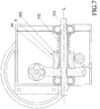
- a wall 311 (see FIG. 2 ) of the casing 31 that is parallel to the side surfaces 420 of the worm gear 42 abuts against a side of the worm gear 42
- the housing unit 3 further includes a limiting member 32 disposed fixedly in the casing 31 (see FIGS. 4 and 5 ) and abuts against an opposite side of the worm gear 42 for preventing the worm gear 42 from being moved along the axis (L) when the joint sleeve 61 is switched between the connection and separation positions.
- the operating portion 623 can be operated to separate the joint sleeve 61 from the worm gear 42 to thereby interrupt rotational force transmission from the motor 2 to the output shaft 51 without the need of additional electricity for driving a DC braking module.
- an energy conservation effect can be achieved.
- the joint sleeve 61 can be switched to the separation position, so that the output shaft 51 can be rotated independently from the rotor (not shown) of the motor 2 and less effort for rotating the output shaft 51 is required. Further, the limiting member 32 prevents the worm gear 42 from being moved along the axis (L) when the joint sleeve 61 is switched between the connection and separation positions.
- the positioning member 63 biased by the biasing member 64 and displacing between the cavities 625 formed in the limiting groove 624 facilitates the operating portion 623 of the switching rod 62 to be moved to desired positions when the joint sleeve 61 is switched between the connection position and the separation position.
- the output unit 5 includes an output shaft 53 for substituting the output shaft 51 in the first embodiment and the transmission key shown in FIG. 2 is omitted.
- the output shaft 53 includes a shaft body 531 extending along the axis (L) and a plurality of spline teeth 532 formed on an outer surface of the shaft body 531 and angularly spaced apart from one another about the axis (L) .
- the clutch unit 6 includes a joint sleeve 66 for substituting the joint sleeve 61 shown in FIG. 2 .
- the joint sleeve 66 includes a sleeve body 661 sleeved on the shaft body 531 and having an inner surface that is formed with a plurality of spline grooves 662 meshing with the spline teeth 532 of the output shaft 53 so as to allow the output shaft 53 to co-rotate with the joint sleeve 66.
- the spline grooves 662 and the spline teeth 532 extend along the direction of the axis (L). In this way, the clutch transmission device of the second embodiment has the same advantages as the first embodiment.
- the clutch unit 6 includes a joint sleeve 67 for substituting the joint sleeve 66 shown in FIG. 6 .
- the joint sleeve 67 includes a sleeve body 671 configured as a cylinder, sleeved on the output shaft 53, having an inner surface that is formed with a plurality of spline grooves 672 meshing with the spline teeth 532 of the output shaft 53 so as to allow the output shaft 53 to co-rotate with the joint sleeve 67.
- the protruding portions 612 shown in FIG. 2 are omitted, and the joint sleeve 67 includes a plurality of meshing portions 673 for substituting the protruding portions 612.
- the meshing portions 673 are angularly and equidistantly spaced apart from one another about the axis (L), and constitute a gear sleeved on the sleeve body 671.
- the clutch transmission device of the third embodiment has the same advantages as the first embodiment.
- the joint sleeve 61, 66 or 67 can be switched easily between the connection position and the separation position so as to enable or disable the output shaft 51 or 53 being driven to rotate by the motor 2. Further, no electricity is required when the joint sleeve 61, 66 or 67 is switching between the connection position and the separation position, such that an energy conservation effect can be achieved.
- the output shaft 51 or 53 can be rotated independently from the motor 2 and thus less effort for rotating the output shaft 51 or 53 is required for maintenance of the output unit 5.
Landscapes
- Engineering & Computer Science (AREA)
- General Engineering & Computer Science (AREA)
- Mechanical Engineering (AREA)
- Gear Transmission (AREA)
- Connection Of Motors, Electrical Generators, Mechanical Devices, And The Like (AREA)
Priority Applications (1)
| Application Number | Priority Date | Filing Date | Title |
|---|---|---|---|
| EP19212104.4A EP3828432A1 (de) | 2019-11-28 | 2019-11-28 | Kupplungsgetriebevorrichtung |
Applications Claiming Priority (1)
| Application Number | Priority Date | Filing Date | Title |
|---|---|---|---|
| EP19212104.4A EP3828432A1 (de) | 2019-11-28 | 2019-11-28 | Kupplungsgetriebevorrichtung |
Publications (1)
| Publication Number | Publication Date |
|---|---|
| EP3828432A1 true EP3828432A1 (de) | 2021-06-02 |
Family
ID=68731823
Family Applications (1)
| Application Number | Title | Priority Date | Filing Date |
|---|---|---|---|
| EP19212104.4A Withdrawn EP3828432A1 (de) | 2019-11-28 | 2019-11-28 | Kupplungsgetriebevorrichtung |
Country Status (1)
| Country | Link |
|---|---|
| EP (1) | EP3828432A1 (de) |
Citations (3)
| Publication number | Priority date | Publication date | Assignee | Title |
|---|---|---|---|---|
| US6561939B1 (en) * | 2001-11-06 | 2003-05-13 | Torque-Traction Technologies, Inc. | Gear module for clutch actuator in differential assembly |
| US20120175887A1 (en) * | 2010-07-14 | 2012-07-12 | Chi-Han Chang | Vehicle Having Two Generators |
| US20140083219A1 (en) * | 2012-09-26 | 2014-03-27 | Kwang Yang Motor Co., Ltd. | Transmission Assembly for a Vehicle |
-
2019
- 2019-11-28 EP EP19212104.4A patent/EP3828432A1/de not_active Withdrawn
Patent Citations (3)
| Publication number | Priority date | Publication date | Assignee | Title |
|---|---|---|---|---|
| US6561939B1 (en) * | 2001-11-06 | 2003-05-13 | Torque-Traction Technologies, Inc. | Gear module for clutch actuator in differential assembly |
| US20120175887A1 (en) * | 2010-07-14 | 2012-07-12 | Chi-Han Chang | Vehicle Having Two Generators |
| US20140083219A1 (en) * | 2012-09-26 | 2014-03-27 | Kwang Yang Motor Co., Ltd. | Transmission Assembly for a Vehicle |
Similar Documents
| Publication | Publication Date | Title |
|---|---|---|
| US4274304A (en) | In-line reversing mechanism | |
| EP2875906B1 (de) | Mehrgängiges Zykloidengetriebe | |
| ES2308666T3 (es) | Mecanismo de cambio de modalidad de trabajo para una herramienta a motor. | |
| US4869131A (en) | Variable speed gearing in rotary electric tool | |
| EP1858666B1 (de) | Kraftbetriebenes schneidwerkzeug | |
| EP0486710A1 (de) | Umkehrbare unidirektionale Übertragung | |
| CN104723259B (zh) | 冲击螺丝批 | |
| EP1647366A1 (de) | Überlastschutz für ein kraftgetriebenes Werkzeug | |
| US20170282344A1 (en) | Output-mode switching device for electric tool | |
| CN108780710B (zh) | 电气设备的马达驱动器 | |
| CN101398037A (zh) | 发电机电机的离合器装置 | |
| EP2138273B1 (de) | Drehwerkzeug mit einem manuellen Ratschenmechanismus | |
| EP3300835A1 (de) | Zubehörklemme und spindelverriegelungsmechanismus für elektrowerkzeugschloss | |
| EP3828432A1 (de) | Kupplungsgetriebevorrichtung | |
| EP3743635B1 (de) | Lastmomentsperre | |
| US9017209B1 (en) | Power tools with reversible, self-shifting transmission | |
| US3087105A (en) | Electromechanical actuator with limiting mechanism | |
| US20200208689A1 (en) | Jamming roller lock | |
| JP2020101252A (ja) | コイルばねを利用したロックタイプ双方向クラッチ | |
| JPS6037419A (ja) | ロータリー・アンテイバツクラツシユ部品 | |
| CN104295620A (zh) | 离合器系统和手持式电动工具 | |
| RU2449187C2 (ru) | Муфта пусковая предохранительная | |
| CN110792761A (zh) | 整合式离合传动装置 | |
| EP1092896B1 (de) | Automatikgetriebe für Handwerkzeug | |
| US7594856B2 (en) | Overload clutch device, clutch disk, and driving toothed wheel |
Legal Events
| Date | Code | Title | Description |
|---|---|---|---|
| PUAI | Public reference made under article 153(3) epc to a published international application that has entered the european phase |
Free format text: ORIGINAL CODE: 0009012 |
|
| STAA | Information on the status of an ep patent application or granted ep patent |
Free format text: STATUS: THE APPLICATION HAS BEEN PUBLISHED |
|
| AK | Designated contracting states |
Kind code of ref document: A1 Designated state(s): AL AT BE BG CH CY CZ DE DK EE ES FI FR GB GR HR HU IE IS IT LI LT LU LV MC MK MT NL NO PL PT RO RS SE SI SK SM TR |
|
| STAA | Information on the status of an ep patent application or granted ep patent |
Free format text: STATUS: THE APPLICATION IS DEEMED TO BE WITHDRAWN |
|
| 18D | Application deemed to be withdrawn |
Effective date: 20211203 |