EP3828490A1 - Raccord - Google Patents
Raccord Download PDFInfo
- Publication number
- EP3828490A1 EP3828490A1 EP19841770.1A EP19841770A EP3828490A1 EP 3828490 A1 EP3828490 A1 EP 3828490A1 EP 19841770 A EP19841770 A EP 19841770A EP 3828490 A1 EP3828490 A1 EP 3828490A1
- Authority
- EP
- European Patent Office
- Prior art keywords
- joint
- refrigerant
- pipe
- heat exchanger
- reinforcement
- Prior art date
- Legal status (The legal status is an assumption and is not a legal conclusion. Google has not performed a legal analysis and makes no representation as to the accuracy of the status listed.)
- Granted
Links
Images




Classifications
-
- F—MECHANICAL ENGINEERING; LIGHTING; HEATING; WEAPONS; BLASTING
- F25—REFRIGERATION OR COOLING; COMBINED HEATING AND REFRIGERATION SYSTEMS; HEAT PUMP SYSTEMS; MANUFACTURE OR STORAGE OF ICE; LIQUEFACTION SOLIDIFICATION OF GASES
- F25B—REFRIGERATION MACHINES, PLANTS OR SYSTEMS; COMBINED HEATING AND REFRIGERATION SYSTEMS; HEAT PUMP SYSTEMS
- F25B9/00—Compression machines, plants or systems, in which the refrigerant is air or other gas of low boiling point
- F25B9/002—Compression machines, plants or systems, in which the refrigerant is air or other gas of low boiling point characterised by the refrigerant
- F25B9/008—Compression machines, plants or systems, in which the refrigerant is air or other gas of low boiling point characterised by the refrigerant the refrigerant being carbon dioxide
-
- F—MECHANICAL ENGINEERING; LIGHTING; HEATING; WEAPONS; BLASTING
- F24—HEATING; RANGES; VENTILATING
- F24F—AIR-CONDITIONING; AIR-HUMIDIFICATION; VENTILATION; USE OF AIR CURRENTS FOR SCREENING
- F24F1/00—Room units for air-conditioning, e.g. separate or self-contained units or units receiving primary air from a central station
- F24F1/06—Separate outdoor units, e.g. outdoor unit to be linked to a separate room comprising a compressor and a heat exchanger
- F24F1/14—Heat exchangers specially adapted for separate outdoor units
- F24F1/16—Arrangement or mounting thereof
-
- F—MECHANICAL ENGINEERING; LIGHTING; HEATING; WEAPONS; BLASTING
- F24—HEATING; RANGES; VENTILATING
- F24F—AIR-CONDITIONING; AIR-HUMIDIFICATION; VENTILATION; USE OF AIR CURRENTS FOR SCREENING
- F24F1/00—Room units for air-conditioning, e.g. separate or self-contained units or units receiving primary air from a central station
- F24F1/06—Separate outdoor units, e.g. outdoor unit to be linked to a separate room comprising a compressor and a heat exchanger
- F24F1/14—Heat exchangers specially adapted for separate outdoor units
- F24F1/18—Heat exchangers specially adapted for separate outdoor units characterised by their shape
-
- F—MECHANICAL ENGINEERING; LIGHTING; HEATING; WEAPONS; BLASTING
- F25—REFRIGERATION OR COOLING; COMBINED HEATING AND REFRIGERATION SYSTEMS; HEAT PUMP SYSTEMS; MANUFACTURE OR STORAGE OF ICE; LIQUEFACTION SOLIDIFICATION OF GASES
- F25B—REFRIGERATION MACHINES, PLANTS OR SYSTEMS; COMBINED HEATING AND REFRIGERATION SYSTEMS; HEAT PUMP SYSTEMS
- F25B1/00—Compression machines, plants or systems with non-reversible cycle
- F25B1/10—Compression machines, plants or systems with non-reversible cycle with multi-stage compression
-
- F—MECHANICAL ENGINEERING; LIGHTING; HEATING; WEAPONS; BLASTING
- F25—REFRIGERATION OR COOLING; COMBINED HEATING AND REFRIGERATION SYSTEMS; HEAT PUMP SYSTEMS; MANUFACTURE OR STORAGE OF ICE; LIQUEFACTION SOLIDIFICATION OF GASES
- F25B—REFRIGERATION MACHINES, PLANTS OR SYSTEMS; COMBINED HEATING AND REFRIGERATION SYSTEMS; HEAT PUMP SYSTEMS
- F25B13/00—Compression machines, plants or systems, with reversible cycle
-
- F—MECHANICAL ENGINEERING; LIGHTING; HEATING; WEAPONS; BLASTING
- F25—REFRIGERATION OR COOLING; COMBINED HEATING AND REFRIGERATION SYSTEMS; HEAT PUMP SYSTEMS; MANUFACTURE OR STORAGE OF ICE; LIQUEFACTION SOLIDIFICATION OF GASES
- F25B—REFRIGERATION MACHINES, PLANTS OR SYSTEMS; COMBINED HEATING AND REFRIGERATION SYSTEMS; HEAT PUMP SYSTEMS
- F25B31/00—Compressor arrangements
- F25B31/002—Lubrication
- F25B31/004—Lubrication oil recirculating arrangements
-
- F—MECHANICAL ENGINEERING; LIGHTING; HEATING; WEAPONS; BLASTING
- F25—REFRIGERATION OR COOLING; COMBINED HEATING AND REFRIGERATION SYSTEMS; HEAT PUMP SYSTEMS; MANUFACTURE OR STORAGE OF ICE; LIQUEFACTION SOLIDIFICATION OF GASES
- F25B—REFRIGERATION MACHINES, PLANTS OR SYSTEMS; COMBINED HEATING AND REFRIGERATION SYSTEMS; HEAT PUMP SYSTEMS
- F25B39/00—Evaporators; Condensers
-
- F—MECHANICAL ENGINEERING; LIGHTING; HEATING; WEAPONS; BLASTING
- F25—REFRIGERATION OR COOLING; COMBINED HEATING AND REFRIGERATION SYSTEMS; HEAT PUMP SYSTEMS; MANUFACTURE OR STORAGE OF ICE; LIQUEFACTION SOLIDIFICATION OF GASES
- F25B—REFRIGERATION MACHINES, PLANTS OR SYSTEMS; COMBINED HEATING AND REFRIGERATION SYSTEMS; HEAT PUMP SYSTEMS
- F25B41/00—Fluid-circulation arrangements
-
- F—MECHANICAL ENGINEERING; LIGHTING; HEATING; WEAPONS; BLASTING
- F28—HEAT EXCHANGE IN GENERAL
- F28D—HEAT-EXCHANGE APPARATUS, NOT PROVIDED FOR IN ANOTHER SUBCLASS, IN WHICH THE HEAT-EXCHANGE MEDIA DO NOT COME INTO DIRECT CONTACT
- F28D1/00—Heat-exchange apparatus having stationary conduit assemblies for one heat-exchange medium only, the media being in contact with different sides of the conduit wall, in which the other heat-exchange medium is a large body of fluid, e.g. domestic or motor car radiators
- F28D1/02—Heat-exchange apparatus having stationary conduit assemblies for one heat-exchange medium only, the media being in contact with different sides of the conduit wall, in which the other heat-exchange medium is a large body of fluid, e.g. domestic or motor car radiators with heat-exchange conduits immersed in the body of fluid
- F28D1/04—Heat-exchange apparatus having stationary conduit assemblies for one heat-exchange medium only, the media being in contact with different sides of the conduit wall, in which the other heat-exchange medium is a large body of fluid, e.g. domestic or motor car radiators with heat-exchange conduits immersed in the body of fluid with tubular conduits
-
- F—MECHANICAL ENGINEERING; LIGHTING; HEATING; WEAPONS; BLASTING
- F28—HEAT EXCHANGE IN GENERAL
- F28F—DETAILS OF HEAT-EXCHANGE AND HEAT-TRANSFER APPARATUS, OF GENERAL APPLICATION
- F28F1/00—Tubular elements; Assemblies of tubular elements
- F28F1/02—Tubular elements of cross-section which is non-circular
- F28F1/022—Tubular elements of cross-section which is non-circular with multiple channels
-
- F—MECHANICAL ENGINEERING; LIGHTING; HEATING; WEAPONS; BLASTING
- F28—HEAT EXCHANGE IN GENERAL
- F28F—DETAILS OF HEAT-EXCHANGE AND HEAT-TRANSFER APPARATUS, OF GENERAL APPLICATION
- F28F9/00—Casings; Header boxes; Auxiliary supports for elements; Auxiliary members within casings
- F28F9/26—Arrangements for connecting different sections of heat-exchange elements, e.g. of radiators
-
- F—MECHANICAL ENGINEERING; LIGHTING; HEATING; WEAPONS; BLASTING
- F28—HEAT EXCHANGE IN GENERAL
- F28F—DETAILS OF HEAT-EXCHANGE AND HEAT-TRANSFER APPARATUS, OF GENERAL APPLICATION
- F28F9/00—Casings; Header boxes; Auxiliary supports for elements; Auxiliary members within casings
- F28F9/26—Arrangements for connecting different sections of heat-exchange elements, e.g. of radiators
- F28F9/262—Arrangements for connecting different sections of heat-exchange elements, e.g. of radiators for radiators
- F28F9/268—Arrangements for connecting different sections of heat-exchange elements, e.g. of radiators for radiators by permanent joints, e.g. by welding
-
- F—MECHANICAL ENGINEERING; LIGHTING; HEATING; WEAPONS; BLASTING
- F25—REFRIGERATION OR COOLING; COMBINED HEATING AND REFRIGERATION SYSTEMS; HEAT PUMP SYSTEMS; MANUFACTURE OR STORAGE OF ICE; LIQUEFACTION SOLIDIFICATION OF GASES
- F25B—REFRIGERATION MACHINES, PLANTS OR SYSTEMS; COMBINED HEATING AND REFRIGERATION SYSTEMS; HEAT PUMP SYSTEMS
- F25B2313/00—Compression machines, plants or systems with reversible cycle not otherwise provided for
- F25B2313/025—Compression machines, plants or systems with reversible cycle not otherwise provided for using multiple outdoor units
- F25B2313/0252—Compression machines, plants or systems with reversible cycle not otherwise provided for using multiple outdoor units with bypasses
-
- F—MECHANICAL ENGINEERING; LIGHTING; HEATING; WEAPONS; BLASTING
- F25—REFRIGERATION OR COOLING; COMBINED HEATING AND REFRIGERATION SYSTEMS; HEAT PUMP SYSTEMS; MANUFACTURE OR STORAGE OF ICE; LIQUEFACTION SOLIDIFICATION OF GASES
- F25B—REFRIGERATION MACHINES, PLANTS OR SYSTEMS; COMBINED HEATING AND REFRIGERATION SYSTEMS; HEAT PUMP SYSTEMS
- F25B2313/00—Compression machines, plants or systems with reversible cycle not otherwise provided for
- F25B2313/025—Compression machines, plants or systems with reversible cycle not otherwise provided for using multiple outdoor units
- F25B2313/0253—Compression machines, plants or systems with reversible cycle not otherwise provided for using multiple outdoor units in parallel arrangements
-
- F—MECHANICAL ENGINEERING; LIGHTING; HEATING; WEAPONS; BLASTING
- F25—REFRIGERATION OR COOLING; COMBINED HEATING AND REFRIGERATION SYSTEMS; HEAT PUMP SYSTEMS; MANUFACTURE OR STORAGE OF ICE; LIQUEFACTION SOLIDIFICATION OF GASES
- F25B—REFRIGERATION MACHINES, PLANTS OR SYSTEMS; COMBINED HEATING AND REFRIGERATION SYSTEMS; HEAT PUMP SYSTEMS
- F25B2600/00—Control issues
- F25B2600/25—Control of valves
- F25B2600/2501—Bypass valves
-
- F—MECHANICAL ENGINEERING; LIGHTING; HEATING; WEAPONS; BLASTING
- F28—HEAT EXCHANGE IN GENERAL
- F28D—HEAT-EXCHANGE APPARATUS, NOT PROVIDED FOR IN ANOTHER SUBCLASS, IN WHICH THE HEAT-EXCHANGE MEDIA DO NOT COME INTO DIRECT CONTACT
- F28D21/00—Heat-exchange apparatus not covered by any of the groups F28D1/00 - F28D20/00
- F28D2021/0019—Other heat exchangers for particular applications; Heat exchange systems not otherwise provided for
- F28D2021/0068—Other heat exchangers for particular applications; Heat exchange systems not otherwise provided for for refrigerant cycles
-
- F—MECHANICAL ENGINEERING; LIGHTING; HEATING; WEAPONS; BLASTING
- F28—HEAT EXCHANGE IN GENERAL
- F28F—DETAILS OF HEAT-EXCHANGE AND HEAT-TRANSFER APPARATUS, OF GENERAL APPLICATION
- F28F2225/00—Reinforcing means
- F28F2225/04—Reinforcing means for conduits
Definitions
- the present disclosure relates to a joint that connects a multi-hole flat pipe and a cylindrical pipe and that allows a carbon dioxide refrigerant to pass therethrough.
- Multi-hole flat pipes are used in refrigeration apparatus that use carbon dioxide as working fluid.
- the multi-hole flat pipe is sometimes connected to a cylindrical pipe, and joints for connecting these have been proposed (see, for example, PTL 1 ( WO2014/199514 )).
- a joint according to a first aspect is a joint that allows a CO 2 refrigerant to pass therethrough.
- the joint connects a multi-hole flat pipe and a cylindrical pipe to each other.
- the multi-hole flat pipe has a thickness T and a width W. W > T.
- the width direction of the multi-hole pipe is a direction in which a plurality of holes are arranged.
- a thickness direction and a width direction of the multi-hole flat pipe are respectively defined as a vertical direction and a horizontal direction of the joint.
- the joint includes a first connection portion and a body.
- the first connection portion covers an outer side of an end portion of the multi-hole flat pipe.
- the body is continuous from the first connection.
- An inside dimension of the body in the vertical direction is larger than an inside dimension of the first connection portion in the vertical direction.
- a joint according to a second aspect is the joint according to the first aspect, in which the body has a region whose inside dimension in the vertical direction gradually increases with increasing distance from the first connection portion.
- a joint according to a third aspect is the joint according to the first aspect or the second aspect, further including a second connection portion.
- the second connection portion is continuous from the body.
- the second connection portion covers an outer side of an end portion of the cylindrical pipe.
- a joint according to a fourth aspect is the joint according to the third aspect, in which the first connection portion is formed by processing one end of a cylindrical pipe.
- the joint according to the fourth aspect can be manufactured by processing a cylindrical pipe, the cost of manufacturing the joint is low.
- a joint according to a fifth aspect is the joint according to the third or fourth aspect, in which a thickness of a pipe of the joint is larger than a thickness of the cylindrical pipe.
- the "cylindrical pipe” means a cylindrical pipe to which the joint is connected.
- a joint according to a sixth aspect is the joint according to any one of the first to fifth aspects, further including a reinforcement portion.
- the reinforcement portion increases a strength of the joint.
- the joint according to the sixth aspect can easily maintain strength even when the refrigerant pressure in the body is high, because the reinforcement portion is used.
- a joint according to a seventh aspect is the joint according to any one of the first to sixth aspects that is constituted by two or more members that are bonded to each other.
- a joint according to an eighth aspect is the joint according to the first or second aspect, in which the body is a part of the cylindrical pipe.
- a joint according to a ninth aspect is the joint according to any one of the first to eighth aspects, further including a flat portion that is continuous from the body and that does not form a passage for the refrigerant.
- a joint according to a tenth aspect is the joint according to the sixth aspect, in which the reinforcement portion is disposed in a refrigerant flow passage so as to extend in the vertical direction.
- the joint according to the tenth aspect can suppress expansion of the inside of the body in the vertical direction, because the reinforcement portion is disposed in a refrigerant flow passage so as to extend in the vertical direction.
- a joint according to an eleventh aspect is the joint according to the sixth aspect, in which the reinforcement portion is disposed outside of a refrigerant flow passage so as to be in contact with an outer surface of the body.
- a joint according to a twelfth aspect is the joint according to the sixth aspect, further including a flat portion that is continuous from the body and that does not form a passage for the refrigerant.
- the reinforcement portion is disposed outside of a refrigerant flow passage so as to be in contact with an outer surface of the body and a surface of the flat portion.
- a heat exchanger includes the joint according to any one of the first to twelfth aspects and a multi-hole flat pipe.
- the multi-hole flat pipe is connected to the joint.
- An air conditioner according to the present disclosure is an air conditioner including the heat exchanger.
- Fig. 1 illustrates the structure of a refrigerant circuit of a refrigeration apparatus 1 according to a first embodiment.
- the refrigeration apparatus 1 according to the present embodiment is an apparatus that uses carbon dioxide, which is a refrigerant that operates in a supercritical region, and that performs two-stage-compression refrigeration cycle.
- the refrigeration apparatus 1 according to the present embodiment can be used as an air conditioner that performs cooling and heating, a water cooler/heater, or the like.
- a refrigerant circuit of the refrigeration apparatus 1 mainly includes a compressor 2, a four-way switching valve 3, a heat-source-side heat exchanger 4, an expansion mechanism 5, a use-side heat exchanger 6, and an intermediate cooler 7.
- the compressor 2 is a two-stage compressor that compresses refrigerant in two stages by using two compression elements 2c and 2d.
- the compressor 2 sucks refrigerant from a suction pipe 2a, compresses the sucked refrigerant by using the first-stage compression element 2c, and then discharges the refrigerant to an intermediate refrigerant pipe 8.
- the refrigerant discharged to the intermediate refrigerant pipe 8 is further sucked into the second-stage compression element 2d and compressed, and discharged to a discharge pipe 2b.
- the discharge pipe 2b is a refrigerant pipe through which the refrigerant discharged from the compressor 2 flows to the four-way switching valve 3.
- An oil separator 41 and a check valve 42 are disposed in the discharge pipe 2b.
- the oil separator 41 separates refrigeration oil, which is mixed in the refrigerant discharged from the compressor 2, from the refrigerant.
- the separated oil is decompressed in a capillary tube 41c, passes through an oil return pipe 41b, and is returned to the suction pipe 2a of the compressor 2.
- the refrigeration oil in the present embodiment is not limited, as long as the refrigeration oil can be used for a CO 2 refrigerant.
- Examples of the refrigeration oil include polyalkylene glycols (PAG) and polyol esters (POE).
- the four-way switching valve 3 can switch the direction of flow of refrigerant, between a forward direction and a backward direction, in a path connecting the heat-source-side heat exchanger 4, the expansion mechanism 5, and the use-side heat exchanger 6.
- the four-way switching valve 3 allows refrigerant flowed out from the compressor 2 to flow from the heat-source-side heat exchanger 4 to the use-side heat exchanger 6.
- the heat-source-side heat exchanger 4 is a radiator
- the use-side heat exchanger 6 is an evaporator.
- the four-way switching valve 3 allows refrigerant flowed out from the compressor 2 to flow from the use-side heat exchanger 6 to the heat-source-side heat exchanger 4.
- the use-side heat exchanger 6 is a radiator
- the heat-source-side heat exchanger 4 is an evaporator.
- the intermediate cooler 7 and a check valve 15 are disposed in the intermediate refrigerant pipe 8. That is, the refrigerant compressed by the first-stage compression element 2c exchanges heat with air in the intermediate cooler 7, and flows into the second-stage compression element 2d again.
- An intermediate-cooler bypass pipe 9 is disposed in the intermediate refrigerant pipe 8 so as to bypass the intermediate cooler 7. That is, the refrigerant flowed through the first-stage compression element 2c and the intermediate-heat-exchanger bypass pipe 9 bypasses the intermediate cooler 7 and flows into the second-stage compression element 2d.
- On-off valves 11 and 12 switch the path of flow of the refrigerant between a path through the intermediate cooler 7 and a path through the intermediate-heat-exchanger bypass pipe 9.
- the on-off valves 11 and 12 are controlled so that the refrigerant flows through the intermediate cooler 7 when the use-side heat exchanger 6 is used as an evaporator and so that the refrigerant flows through the intermediate-heat-exchanger bypass pipe 9 when the use-side heat exchanger 6 is used as a radiator. That is, basically, the intermediate cooler 7 is used during a cooling operation.
- a two-stage compressor is used in the refrigeration apparatus 1 according to the present embodiment, two compressors may be used in a similar way.
- a compressor or a compression mechanism that performs compression of three or more stages may be used.
- Fig. 1 illustrates, in a dotted line, constituent elements of an outdoor unit 10 of the refrigeration apparatus 1 according to the present embodiment.
- Fig. 2 is an external perspective view of the outdoor unit 10.
- the outdoor unit 10 has a casing 20 that contains a fan 40, the compressor 2, the heat-source-side heat exchanger 4, the intermediate cooler 7, the expansion mechanism 5, the four-way switching valve 3, and the oil separator 41.
- Fig. 2 is an external perspective view of the outdoor unit 10.
- Fig. 3A is a partial perspective view of the heat-source-side heat exchanger 4.
- the heat-source-side heat exchanger 4 is disposed on three sides of the inside of the casing 20 of the outdoor unit 10.
- the fan 40 rotates, air around the casing 20 is sucked from the three sides and passes through the heat-source-side heat exchanger 4.
- the air sucked into the casing 20 passes through the fan 40 and is blown upward from the top of the casing 20 to the outside.
- the outdoor unit 10 according to the present embodiment is a top-blow-type unit. The air is heated or cooled by exchanging heat with refrigerant while passing through the heat exchanger 4.
- Fig. 3 is a schematic perspective view illustrating one side of the heat-source-side heat exchanger 4 according to the present embodiment.
- the heat exchanger 4 includes heat transfer tubes 30, in which refrigerant flows, and metal fins 50, which promote heat exchange between the refrigerant and air.
- Each of the heat transfer tubes 30 according to the present embodiment is a multi-hole flat pipe. In the multi-hole flat pipe, a plurality of holes, through which refrigerant flows, are arranged in the width direction.
- refrigerant is supplied from the outside of the heat exchanger 4 into the heat transfer tubes 30 at a first end portion 4a.
- the refrigerant flows from the first end portion 4a along three sides of the heat transfer tubes 30, each of which is bent by 90° at two positions, and reaches a second end portion 4b.
- the direction of flow of refrigerant is reversed by 180°.
- the refrigerant flows along the three sides again and returns to the first end portion 4a.
- the refrigerant flows out from the heat transfer tubes 30 to the outside of the heat exchanger 4.
- first heat transfer tubes 30a heat transfer tubes that form refrigerant flow passages extending from the first end portion 4a to the second end portion 4b
- second heat transfer tubes 30b heat transfer tubes through which refrigerant flows in the opposite direction
- the heat transfer tubes 30 are arranged in two rows with respect to the flow of air. In each of the rows, the first heat transfer tubes 30a and the second heat transfer tubes 30b are arranged alternately in the vertical direction.
- the direction of flow of refrigerant in the heat exchanger 4 is basically the direction in which the refrigerant flows when the heat exchanger is used as a radiator.
- the direction of flow of refrigerant is reversed.
- a portion of the first heat transfer tube 30a near the second end portion 4b will be referred to as a first linear portion 31, and a portion of the second heat transfer tube 30b near the second end portion 4b will be referred to as a second linear portion 32.
- the reversely bent portion 33 reverses the direction of flow of refrigerant that has flowed through the first linear portion 31 of the heat transfer tube 30 (a multi-hole flat pipe 300) and allows the refrigerant to flow to the second linear portion 32 below the first linear portion 31.
- the reversely bent portion 33 is formed from two joints 34a and 34b and a U-shaped pipe 350.
- the joints 34a and 34b connect the heat transfer tubes 30 and the U-shaped pipe 350.
- the heat transfer tube 30 may be a multi-hole flat pipe or a cylindrical pipe, and is not limited.
- the multi-hole flat pipe 300 is used.
- a multi-hole flat pipe has high performance in transferring heat between refrigerant and the heat transfer tube.
- a plurality of holes are arranged in a row.
- the direction in which the holes of the multi-hole flat pipe are arranged will be referred to as the width direction, and the direction that is perpendicular to the width direction and the direction of flow of refrigerant will be referred to as the thickness direction.
- W > T holds, where T is the thickness (length in the thickness direction) and W is the width (length in the width direction) of the multi-hole flat pipe.
- refrigerants that have flowed through channels, which are the plurality of holes of the multi-hole flat pipe 300, are collected to one channel in the reversely bent portion 33. Then, in the reversely bent portion 33, that is, in the joints 34a and 34b and the U-shaped pipe, the refrigerants can be made uniform.
- the thickness T of the heat transfer tube 30 in the vertical direction is 3 mm or smaller.
- the distance DP between the center of the first linear portion 31 and the center of the second linear portion 32 in the vertical direction is 0 mm to 21 mm.
- the first linear portion 31 and the second linear portion 32, between which the reversely bent portion 33 of the heat transfer tube 30 is located are disposed close to each other. Therefore, nonuniformity in the temperature of passing air can be reduced. Thus, heat exchange efficiency is also improved.
- the distance DP between the center of the first linear portion 31 and the center of the second linear portion 32 in the vertical direction is smaller than or equal to five times the thickness T of the heat transfer tubes 30 in the vertical direction.
- the first linear portion 31 and the second linear portion 32, between which the reversely bent portion 33 of the heat transfer tube 30 is located are disposed close to each other. Therefore, nonuniformity in the temperature of passing air can be reduced.
- the heat exchanger 4 further includes the plurality of fins 50.
- the fins 50 are fixed to the heat transfer tubes 30 and promote heat exchange between the heat transfer tubes 30 and air.
- the fin pitch of the plurality of fins 50 is 1.3 mm or larger, and preferably 1.4 mm or larger.
- the thickness T of the heat transfer tube 30 in the vertical direction is 3 mm or smaller.
- heat exchange efficiency can be improved.
- the temperature difference between the refrigerant inlet temperature and the refrigerant outlet temperature of the heat exchanger 4 is 40°C or larger.
- a CO 2 refrigerant is used as the refrigerant.
- the CO 2 refrigerant is a refrigerant used in a supercritical region, and decrease of the temperature of the refrigerant in the radiator is large. The temperature decreases by 40°C or more. Because the temperature difference of the refrigerant is large, the effect of disposing the first linear portion 31 and the second linear portion 32 close to each other is also large.
- the second linear portion 32 is located above or below the first linear portion 31.
- the heat exchanger 4 can further reduce nonuniformity in temperature of passing air. Because spaces above and below the heat transfer tube 30 are connected by the fins 50, the surrounding temperatures of regions around the heat transfer tube 30 become close to each other via the fins 50.
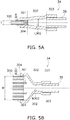
- Fig. 5A is a vertical sectional view of a joint 34
- Fig. 5B is a horizontal sectional view of the joint 34.
- the joint 34 according to the present embodiment connects the multi-hole flat pipe 300 and a cylindrical pipe 35 to each other.
- the cylindrical pipe 35 is the U-shaped pipe 350.
- Refrigerant that flows through these pipes is a CO 2 refrigerant.
- the joint 34 includes a first connection portion 301, a body 302, and a second connection portion 303.
- the first connection portion 301 covers an outer part of an end portion of the multi-hole flat pipe 300.
- the body 302 is continuous from the first connection portion 301.
- the second connection portion 303 is continuous from the body.
- the second connection portion 303 covers an outer side of an end portion of the cylindrical pipe 35.
- the inside dimension L 301 of the first connection portion 301 in the vertical direction is slightly larger than the thickness T of the multi-hole flat pipe 300.
- the inside dimension L 302 of the body 302 in the vertical direction is larger than the inside dimension L 301 of the first connection portion 301 in the vertical direction.
- the inside dimension L 302 of the body 302 in the vertical direction increases with increasing distance from the first connection portion 301, and becomes constant at some portion.
- the inside dimension W 301 of the first connection portion 301 in the horizontal direction is slightly larger than the width W of the multi-hole flat pipe 300.
- the inside dimension W 302 of the body 302 in the horizontal direction is larger than the inside dimension W 301 of the first connection portion 301 in the horizontal direction.
- the inside dimension W 302 of the body 302 in the horizontal direction decreases with increasing distance from the first connection portion 301, and becomes constant at some portion.
- the length of the portion where the inside dimension W 302 in the horizontal direction is constant is the same as the length of the portion where the inside dimension L 302 in the vertical direction is constant.
- the inside diameter of the cylindrical pipe 35, which is connected to one side of the joint 34, is larger than the dimension of a hole of the multi-hole flat pipe 300, which is connected to the other side of the joint 34, in the thickness direction.
- the thickness of the pipe of the joint 34 is larger than the thickness of the cylindrical pipe 35.
- the joint 34 further includes a reinforcement portion 304 that is disposed in a refrigerant flow passage so as to extend in the vertical direction.
- the reinforcement portion 304 is constituted by a reinforcement member.
- the reinforcement portion 304 is disposed near the first connection portion 301.
- the reinforcement portion 304 which connects upper and lower parts of the pipe of the joint 34, serves as a reinforcement when receiving a tensile stress and when a compressive stress is received in the vertical direction in Fig. 5A .
- the reinforcement portion is used, because a CO 2 refrigerant has high pressure and the first connection portion 301 has a flat shape.
- a first method of manufacturing the joint 34 is a method in which a cylindrical pipe is used.
- the cylindrical pipe is an ordinary cylindrical pipe having a uniform inside diameter.
- the wall thickness of a cylindrical pipe used as a material is larger than the wall thickness of the cylindrical pipe 35 to be connected.
- one end of the cylindrical pipe is flattened. Then, the cylindrical pipe is processed so that the inside dimension L 301 of an end portion in the vertical direction becomes slightly larger than the thickness T of the multi-hole flat pipe 300 and so that the inside dimension W 301 of the end portion in the horizontal direction becomes slightly larger than the width W of the multi-hole flat pipe 300.
- this manufacturing method although manufacturing can be performed comparatively easily, it is difficult to insert the reinforcement portion 304. Accordingly, this manufacturing method is used when the reinforcement portion 304 is not used.
- a second method of manufacturing the joint 34 uses a bonding technique.
- the reinforcement portion 304 is bonded beforehand to the upper part or the lower part by brazing or the like.
- the joint 34 is formed by bonding the upper part and the lower part to each other by brazing or the like.
- the intermediate cooler 7 is disposed on the upstream side of the heat exchanger 4 in the airflow direction and inside the casing 20 so as to be independent from the heat exchanger 4.
- independent means: the fins 50 of the heat exchanger 4 and fins (not shown) of the intermediate cooler 7 are not connected; and the heat exchanger 4 and the intermediate cooler 7 have respective refrigerant ports.
- the intermediate cooler is disposed at a height that is larger than half the height at which the heat exchanger 4 is disposed.
- the fan 40 is disposed above the heat exchanger 4 and the intermediate cooler 7, and the airflow speed increases also along a side of the heat exchanger 4 as a position becomes higher.
- the intermediate cooler 7 is disposed upstream of the heat exchanger 4, can make the difference in temperature between air and refrigerant sufficiently large, and can increase the heat exchange amount.
- the intermediate cooler 7 is disposed in an upper part, where the amount of airflow is comparatively large, the intermediate cooler 7 can increase the heat exchange amount.
- the joint 34 is used in the refrigeration apparatus 1 that uses a CO 2 refrigerant.
- the joint 34 connects the multi-hole flat pipe 300 and the cylindrical pipe 35 to each other.
- the joint 34 includes the first connection portion 301, the body 302, and the second connection portion 303.
- the first connection portion 301 covers an outer side of an end portion of the multi-hole flat pipe.
- the body 302 is continuous from the first connection portion 301.
- the second connection portion 303 is continuous from the body, and covers an outer side of an end portion of the cylindrical pipe.
- the inside dimension L 302 of the body 302 in the vertical direction is larger than the inside dimension L 301 of the first connection portion in the vertical direction. Therefore, oil is unlikely to accumulate on the inner peripheral surface of the joint 34 around the connection portion.
- the body 302 further has a region whose inside dimension in the vertical direction gradually increases with increasing distance from the first connection portion 301.
- the joint 34 according to the present embodiment is formed by processing one end of a cylindrical pipe in one manufacturing method.
- the wall thickness of the cylindrical pipe used as a material is larger than the wall thickness of the cylindrical pipe 35 to be connected.
- the original portion of the cylindrical pipe used as a material becomes a part of the body 302, the part where the inside dimensions L 302 and W 302 are each uniform.
- the joint 34 according to the present embodiment can be manufactured by performing simple processing on a cylindrical pipe, manufacturing cost can be reduced.
- the wall thickness of the pipe of the joint 34 according to the present embodiment is larger than the thickness of the cylindrical pipe 35.
- the reason for making the wall thickness of the joint 34 larger is that the joint 34, having a flat part, needs to have a higher strength than the cylindrical pipe 35.
- the joint according to the present embodiment further includes the reinforcement portion 304.
- the reinforcement portion 304 is disposed in a refrigerant flow passage of the joint 34 so as to extend in the vertical direction.
- the reinforcement portion 304 connects an upper part and a lower part of inner wall of the joint 34.
- the reinforcement portion 304 serves as a reinforcement when receiving a tensile stress and when receiving a compressive stress from above and below the joint 34.
- the reinforcement portion 304 is used, because a CO 2 refrigerant has high pressure and the first connection portion 301 has a flat shape.
- the joint 34 according to the present embodiment may be manufactured by bonding two or more members to each other. By using the bonding method, it is possible to easily manufacture a joint having a complex structure, such as a joint including the reinforcement portion 304.
- the joint 34 is separate from the multi-hole flat pipe 300 and the cylindrical pipe 35.
- the joint 34 is integrated with the cylindrical pipe 35.
- modification 1A is similar to the first embodiment.
- the joint 34 according to modification 1A has features that are similar to those described in (3-1) to (3-3) and (3-5).
- the reversely bent portion 33 illustrated in Fig. 4 may be formed as a unit in which the joint 34a, the U-shaped pipe 350, and the joint 34b are integrated.
- the heat transfer tube 30 is reversely bent vertically. That is, the first linear portion 31 and the second linear portion 32 belong to the same row. In the heat exchanger 4 according to the second embodiment, the heat transfer tube 30 is reversely bent across rows. In other respects, the structure of the refrigeration apparatus 1 according to the second embodiment is the same as that of each of the first embodiment and modification 1A.
- Figs. 7A and 7B are side views of the first end portion 4a and the second end portion 4b as seen in the direction in which refrigerant flows.
- Fig. 6B is a sectional view of a middle portion between the first end portion 4a and the second end portion 4b, taken along a section S perpendicular to the direction in which refrigerant flows.
- the first heat transfer tubes 30a are heat transfer tubes through which refrigerant flows from the first end portion 4a to the second end portion 4b
- the second heat transfer tubes 30b are heat transfer tubes through which refrigerant flows in the opposite direction.
- refrigerant flows into a first refrigerant port 401 illustrated in Fig. 7A .
- the refrigerant flows through the first heat transfer tube 30a from the first refrigerant port 401, passes along three sides of the heat exchanger 4, exchanges heat with air, and reaches the second end portion 4b.
- the refrigerant that has reached the second end portion 4b is reversed by the reversely bent portion 33 to another row (here, an adjacent row on the upstream side in the airflow direction).
- the distance DP between the center of the first heat transfer tube 30a (the first linear portion 31) and the center of the second heat transfer tube 30b (the second linear portion 32) in the vertical direction is 21 mm or smaller.
- the structure of the reversely bent portion 33 according to the present embodiment is similar to that of modification 1A. That is, the first heat transfer tube 30a and the second heat transfer tube 30b are connected via two joints 34 and the U-shaped pipe 350 that connects the two joints 34.
- the heat transfer tubes 30a and 30b according to the present embodiment are arranged vertically at a pitch P.
- the distance DP between the center of the first heat transfer tube 30a (the first linear portion 31) and the center of the second heat transfer tube 30b (the second linear portion 32) in the vertical direction is larger than 0 and smaller than DP. That is, 0 ⁇ DP ⁇ P.
- the refrigerant that has been reversed in the second end portion 4b flows through the second heat transfer tubes 30b, exchanges heat with air while passing along three sides, and reaches the first end portion 4a.
- the refrigerant that has reached the first end portion flows out from a second refrigerant port 402 to a refrigerant circuit outside of the heat exchanger 4.
- first heat transfer tube 30a is disposed downstream in the airflow direction and the second heat transfer tube 30b is disposed upstream in the airflow direction has been described.
- the disposition may be opposite to this.
- the heat transfer tube 30 extends only one cycle between the first end portion 4a and the second end portion 4b has been described.
- the present disclosure is effective also in a case where the heat transfer tube 30 extends two or more cycles between the first and second end portions 4a and 4b.
- the heat exchanger according to the second embodiment has the advantageous effects described in (3-1) to (3-3) and (3-5) to (3-7).
- the first heat transfer tube 30a and the second heat transfer tube 30b that are connected via the reversely bent portion 33 are in rows that are adjacent to and different from each other. Accordingly, when the same row is seen, the first heat transfer tubes 30a and the second heat transfer tubes 30b in which refrigerants having different temperatures flow are not arranged side by side, and nonuniform distribution of temperature in the row is reduced.
- the first heat transfer tube 30a and the second heat transfer tube 30b that are connected via the reversely bent portion 33 are in rows that are adjacent to and different from each other. Moreover, the distance DP between the center of the first heat transfer tube 30a (the first linear portion 31) and the center of the second heat transfer tube 30b (the second linear portion 32) in the vertical direction is larger than 0 and smaller than DP.
- the second heat transfer tube 30b does not block airflow to the first heat transfer tube 30a, which is located downstream in the airflow direction, and heat exchange between air and refrigerant is promoted.
- the first refrigerant port 401 and the second refrigerant port 402 are arranged in different rows. Accordingly, for example, when a refrigerant manifold is additionally disposed at a refrigerant port, a connection pipe can be simply formed easily.
- Fig. 6A is a sectional view of a the heat exchanger 4 according to modification 2A, taken along a section S perpendicular to the direction in which refrigerant flows at a midpoint between the first end portion 4a and the second end portion 4b.
- Modification 2A differs from the second embodiment in that the distance DP between the center of the first heat transfer tube 30a (the first linear portion 31) and the center of the second heat transfer tube 30b (the second linear portion 32) in the vertical direction at the reversely bent portion 33, for reversing the flow of refrigerant, at the second end portion 4b is 0.
- modification 2A is the same as the second embodiment.
- the heat exchanger according to modification 2A has features similar to those of the heat exchanger 4 according to the second embodiment described in (6-1) to (6-3).
- Joints 34a to 34e connect the multi-hole flat pipe 300 and the cylindrical pipe 35 to each other, and allow a CO 2 refrigerant to pass therethrough.
- the joints 34a to 34e include the first connection portion 301, the body 302 continuous from the first connection portion 301, and reinforcement portions 304a to 304e.
- the first connection portion 301 covers an outer side of an end portion of the multi-hole flat pipe 300.
- the body 302 is continuous from the first connection portion 301.
- the reinforcement portions 304a to 304e increase the strength of the joints 34a to 34e.
- the joints 34a to 34e according to the present embodiment are connected to the multi-hole flat pipe 300, the joints 34a to 34e have flat shapes, and a stress is likely to concentrate on a local part thereof. Moreover, a high stress is applied to the joints, because a CO 2 refrigerant is used with high pressure. Furthermore, considering that fact that the multi-hole flat pipes 300 are stacked and used, it is not possible to unnecessarily increase the thickness of the pipe wall of the body 302.
- the joints 34a to 34e according to the present embodiment have the reinforcement portions 304a to 304e, when used for a CO 2 refrigerant, it is possible to reduce deformation and breakage of the joints 34a to 34e even if the pressure of the inside of the joints 34a to 34e becomes high.
- the joint 34e according to the present embodiment may further include flat portions 305 that are continuous from the body 302 and that do not form a passage for the refrigerant.
- the thickness T and the width W of the multi-hole flat pipe 300 are defined in the same way as in the first embodiment.
- the thickness direction and the width direction of the multi-hole flat pipe 300 are respectively defined as the vertical direction and the horizontal direction of the joint 34.
- the reinforcement portions 304a and 304b according to the present embodiment may be disposed in a refrigerant flow passage so as to extend in the vertical direction.
- the reinforcement portions 304c to 304e according to the present embodiment may be disposed outside of a refrigerant flow passage so as to be in contact with an outer surface of the body 302.
- the reinforcement portions 304c to 304e By disposing the reinforcement portions 304c to 304e outside of the refrigerant flow passage, the reinforcement portions 304c to 304e do not resist the flow of the refrigerant. Disposing the reinforcement portions 304c to 304e on the outer surface of the body 302 makes manufacturing comparatively easy.
- the reinforcement portions 304e according to the present embodiment may be disposed outside of a refrigerant flow passage so as to be in contact with the outer surface of the body 302 and surfaces of the flat portions 305.
- the joints 34a to 34e according to the present embodiment may further include the second connection portion 303 that is continuous from the body 302 and that covers an outer side of an end portion of the cylindrical pipe 35.
- the first connection portion 301 of the joints 34a to 34e according to the present embodiment may be formed by processing one end of the cylindrical pipe.
- the inside dimension (L 302 ) of the body 302 in the vertical direction may be larger than the inside dimension (L 301 ) of the first connection portion 301 in the vertical direction.
- the body 302 of the joint 34 may have a region whose inside dimension in the vertical direction gradually increases with increasing distance from the first connection portion 301.
- the thickness of the pipe of the joints 34a to 34e may be larger than the thickness of the cylindrical pipe 35.
- the material of the joints 34a to 34e is a metal.
- the metal is aluminum, copper, iron, or an alloy including these.
- the material of the multi-hole flat pipe 300 and the cylindrical pipe 35 is a metal.
- the metal is aluminum, copper, iron, or an alloy including these.
- a first method of manufacturing the joints 34a to 34e is a method in which a cylindrical pipe is used.
- the cylindrical pipe is an ordinary cylindrical pipe having a uniform inside diameter.
- the wall thickness of the cylindrical pipe used as a material is larger than the wall thickness of the cylindrical pipe 35 to be connected.
- one end of the cylindrical pipe is pressed and flattened.
- Figs. 11 and 12 illustrate examples of the joints 34c and 34d manufactured by using the first manufacturing method.
- a second method of manufacturing the joints 34a to 34e uses a bonding technique.
- a joint is formed by deforming two plates and bonding the plates to each other.
- the body 302, the first connection portion 301, and the second connection portion 303 are formed by bonding two deformed plates 3413 and 3414 to each other.
- the material of the reinforcement portion is a metal.
- the metal is aluminum, copper, iron, or an alloy including these.
- the material of the reinforcement portion may be the same as the material of the body. In this case, an advantage is obtained in that a cell reaction is unlikely to occur.
- the material of the reinforcement portion may be different from the material of the body.
- a material having a high thermal conductivity may be used as the material of the body, and a material having a high mechanical strength may be used as the material of the reinforcement portion. Examples of a material having a high thermal conductivity include aluminum and copper, and examples of a material having a high strength include stainless steel (an alloy including iron).
- Fig. 9 is a sectional view of the joint 34a and the reinforcement portion 304a according to example 1 of the third embodiment.
- the reinforcement portion 304a according to example 1 is a bar having projections at both ends.
- the bar extends through two parts, which are an upper part and a lower part, of the body 302 shown in Fig. 9 .
- the reinforcement portion 304a is manufactured, for example, by using a method including: forming a hole in the body 302 of the joint 34a; inserting a bar so as to block the hole; forming projections at both ends of the bar; and sealing the hole of the body 302 by brazing or the like.
- a bolt-like bar having a projection at one end may be inserted from one side of the body 302, and a nut-like object may be attached to the other end to form a projection at the other end.
- the projections suppress the body 302 from deforming so as to expand, even if the pressure of the refrigerant inside the body 302 becomes high and the refrigerant presses the wall of the body 302 outward.
- the reinforcement portion 304a according to example 1 may have only one bar or a plurality of bars.
- the reinforcement portion 304a may be plate-shaped, as with the reinforcement portion 304 illustrated in Figs. 5A and 5B . In this case, preferably, the reinforcement portion 304a extends along a channel through which a refrigerant flows.
- the joint 34a according to the example 1 may be formed by deforming a cylindrical pipe or by bonding two plates to each other.
- the joint 34b according to the example 2 may be formed by deforming a cylindrical pipe or by bonding two plates to each other.
- the reinforcement portion 304b according to example 2 is formed by deforming the body 302 of the joint 34b and by bonding facing parts of the body 302 to each other. Examples of the bonding method include brazing. Accordingly, the reinforcement portion 304b includes a bonded portion 3041.
- Example 2 may have one reinforcement portion 304b or a plurality of reinforcement portions 304b.
- the bonded portion 3041 of the reinforcement portion 304b according to example 2 may have a dot-like shape or a linear shape. In a case where the reinforcement portion 304b extends linearly, preferably, the reinforcement portion 304b may extend along a channel through which the refrigerant flows.
- the joint 34c according to example 3 is formed by deforming a cylindrical pipe.
- the reinforcement portion 304c is a plate (rib) affixed to an outer side of the body 302 of the joint 34c.
- the reinforcement portion 304c is affixed so that that the thickness direction is along the surface of the body 302.
- the body 302 and the reinforcement portion 304c are bonded by brazing.
- the reinforcement portion 304c according to example 3 is disposed on the outer side of the body 302, the reinforcement portion 304c does not obstruct a refrigerant flow passage.
- Example 3 may have one reinforcement portion 304c or a plurality of reinforcement portions 304c.
- the joint 34d according to example 4 is formed by deforming a cylindrical pipe.
- the reinforcement portion 304d is a plate (rib) affixed to an outer side of the body 302 of the joint 34d.
- the reinforcement portion 304d is affixed so that a surface of the plate extends along the surface of the body 302.
- the body 302 and the reinforcement portion 304c are bonded by brazing.
- the reinforcement portion 304d according to example 4 is disposed on the outer side of the body 302, the reinforcement portion 304d does not obstruct a refrigerant flow passage.
- Example 4 may have one reinforcement portion 304d or a plurality of reinforcement portions 304d.
- Advantageous effects of the reinforcement portion 304d according to example 4 are similar to those of a case where the thickness of the body of the pipe of the joint is increased. However, compared with a case where only the thickness of the body of the pipe of the joint is increased, a structure is realized in which only the thickness of a wall to which a high pressure is applied is increased and the thickness of a part to which a high pressure is not applied is reduced.
- the joint 34e according to example 5 is formed by bonding the two plates 3413 and 3414 to each other.
- the joint 34e according to example 5 further includes the flat portions 305. Two of the flat portions 305 are included in the plate 3413 and two of the flat portions 305 are included in the plate 3414, that is, four of the flat portions are included in total.
- the flat portions 305 each may have any appropriate size. The size need not be as large as that shown in Fig. 13 .
- four reinforcement portions 304e are plates (ribs) that are affixed across the boundaries between the body 302 of the joint 34c and the four flat portions 305.
- the reinforcement portions 304e are affixed so that the thickness direction of the plates is along the surface of the body 302.
- the body 302 and the reinforcement portions 304c are bonded by brazing.
- the reinforcement portions 304e according to example 5 are disposed on the outer side of the body 302, the reinforcement portions 304e do not obstruct a refrigerant flow passage.
- the reinforcement portions 304e according to example 5 are bonded also to upper parts of the flat portions 305, the reinforcement portions 304e can provide a higher strength than in a case where the flat portions 305 are not present.
Landscapes
- Engineering & Computer Science (AREA)
- Mechanical Engineering (AREA)
- General Engineering & Computer Science (AREA)
- Physics & Mathematics (AREA)
- Thermal Sciences (AREA)
- Chemical & Material Sciences (AREA)
- Combustion & Propulsion (AREA)
- Geometry (AREA)
- Chemical Kinetics & Catalysis (AREA)
- Heat-Exchange Devices With Radiators And Conduit Assemblies (AREA)
- Other Air-Conditioning Systems (AREA)
Applications Claiming Priority (2)
| Application Number | Priority Date | Filing Date | Title |
|---|---|---|---|
| JP2018139667A JP2021167676A (ja) | 2018-07-25 | 2018-07-25 | 継手 |
| PCT/JP2019/029250 WO2020022443A1 (fr) | 2018-07-25 | 2019-07-25 | Raccord |
Publications (3)
| Publication Number | Publication Date |
|---|---|
| EP3828490A1 true EP3828490A1 (fr) | 2021-06-02 |
| EP3828490A4 EP3828490A4 (fr) | 2021-09-15 |
| EP3828490B1 EP3828490B1 (fr) | 2023-03-08 |
Family
ID=69180768
Family Applications (1)
| Application Number | Title | Priority Date | Filing Date |
|---|---|---|---|
| EP19841770.1A Active EP3828490B1 (fr) | 2018-07-25 | 2019-07-25 | Raccord |
Country Status (3)
| Country | Link |
|---|---|
| EP (1) | EP3828490B1 (fr) |
| JP (1) | JP2021167676A (fr) |
| WO (1) | WO2020022443A1 (fr) |
Families Citing this family (2)
| Publication number | Priority date | Publication date | Assignee | Title |
|---|---|---|---|---|
| CN120738239A (zh) | 2013-08-21 | 2025-10-03 | 联邦科学工业研究组织 | 锈病抗性基因 |
| JP2020165644A (ja) * | 2019-03-29 | 2020-10-08 | ダイキン工業株式会社 | 熱交換器、熱交換器の製造方法及びヘッダアッセンブリの製造方法 |
Family Cites Families (5)
| Publication number | Priority date | Publication date | Assignee | Title |
|---|---|---|---|---|
| JPH07125529A (ja) * | 1993-11-02 | 1995-05-16 | Kansai Pipe Kogyo Kk | 管継手の製造方法 |
| JP2010185614A (ja) * | 2009-02-12 | 2010-08-26 | Mitsubishi Electric Corp | 扁平管継手 |
| JP5195733B2 (ja) * | 2009-12-17 | 2013-05-15 | 三菱電機株式会社 | 熱交換器及びこれを備えた冷凍サイクル装置 |
| EP3009754B1 (fr) | 2013-06-14 | 2017-10-25 | Mitsubishi Electric Corporation | Unité extérieure pour climatiseur et procédé de production pour unité extérieure pour climatiseur |
| JP6355473B2 (ja) * | 2014-08-07 | 2018-07-11 | 三菱電機株式会社 | 熱交換器 |
-
2018
- 2018-07-25 JP JP2018139667A patent/JP2021167676A/ja active Pending
-
2019
- 2019-07-25 EP EP19841770.1A patent/EP3828490B1/fr active Active
- 2019-07-25 WO PCT/JP2019/029250 patent/WO2020022443A1/fr not_active Ceased
Also Published As
| Publication number | Publication date |
|---|---|
| JP2021167676A (ja) | 2021-10-21 |
| EP3828490B1 (fr) | 2023-03-08 |
| EP3828490A4 (fr) | 2021-09-15 |
| WO2020022443A1 (fr) | 2020-01-30 |
Similar Documents
| Publication | Publication Date | Title |
|---|---|---|
| CN103717989B (zh) | 热交换器 | |
| CN104884891B (zh) | 热交换器 | |
| CN101592411B (zh) | 冷冻循环装置 | |
| KR20150051594A (ko) | 냉장고의 냉각 사이클 | |
| CN102066866A (zh) | 热交换器以及具备该热交换器的空气调节机 | |
| CN105452794A (zh) | 热交换器以及热泵装置 | |
| EP3156752B1 (fr) | Échangeur thermique | |
| JP6351875B1 (ja) | 熱交換器及び冷凍サイクル装置 | |
| CN118935814A (zh) | 换热器和空调系统 | |
| CN110945308A (zh) | 热交换器及制冷循环装置 | |
| CN105143808A (zh) | 热交换器、制冷循环装置以及热交换器的制造方法 | |
| EP3828490B1 (fr) | Raccord | |
| CN107003073A (zh) | 耐霜冻微通道热交换器 | |
| JP6890509B2 (ja) | 空気調和機 | |
| CN110285603B (zh) | 热交换器和使用其的制冷系统 | |
| JP2003269822A (ja) | 熱交換器および冷凍サイクル | |
| CN111902683A (zh) | 热交换器及制冷循环装置 | |
| EP3599433A1 (fr) | Unité de source de chaleur pour appareil de réfrigération | |
| CN222012414U (zh) | 微通道换热器、冰箱 | |
| JP5257102B2 (ja) | 熱交換器および冷凍空調装置 | |
| CN113544458B (zh) | 气体集管、热交换器以及制冷循环装置 | |
| EP3734190A1 (fr) | Échangeur de chaleur et dispositif à cycle frigorifique | |
| KR102749268B1 (ko) | 열교환기 및 냉동 사이클 장치 | |
| CN103857977A (zh) | 热交换单元及冷冻装置 | |
| KR101149725B1 (ko) | 열교환기 |
Legal Events
| Date | Code | Title | Description |
|---|---|---|---|
| STAA | Information on the status of an ep patent application or granted ep patent |
Free format text: STATUS: THE INTERNATIONAL PUBLICATION HAS BEEN MADE |
|
| PUAI | Public reference made under article 153(3) epc to a published international application that has entered the european phase |
Free format text: ORIGINAL CODE: 0009012 |
|
| STAA | Information on the status of an ep patent application or granted ep patent |
Free format text: STATUS: REQUEST FOR EXAMINATION WAS MADE |
|
| 17P | Request for examination filed |
Effective date: 20210223 |
|
| AK | Designated contracting states |
Kind code of ref document: A1 Designated state(s): AL AT BE BG CH CY CZ DE DK EE ES FI FR GB GR HR HU IE IS IT LI LT LU LV MC MK MT NL NO PL PT RO RS SE SI SK SM TR |
|
| A4 | Supplementary search report drawn up and despatched |
Effective date: 20210818 |
|
| RIC1 | Information provided on ipc code assigned before grant |
Ipc: F28D 21/00 20060101ALI20210812BHEP Ipc: F28F 1/02 20060101ALI20210812BHEP Ipc: F28D 1/04 20060101ALI20210812BHEP Ipc: F25B 31/00 20060101ALI20210812BHEP Ipc: F25B 13/00 20060101ALI20210812BHEP Ipc: F25B 9/00 20060101ALI20210812BHEP Ipc: F25B 1/10 20060101ALI20210812BHEP Ipc: F24F 1/16 20110101ALI20210812BHEP Ipc: F25B 41/00 20210101ALI20210812BHEP Ipc: F25B 39/00 20060101ALI20210812BHEP Ipc: F25B 1/00 20060101ALI20210812BHEP Ipc: F24F 1/18 20110101ALI20210812BHEP Ipc: F28F 9/26 20060101AFI20210812BHEP |
|
| DAV | Request for validation of the european patent (deleted) | ||
| DAX | Request for extension of the european patent (deleted) | ||
| STAA | Information on the status of an ep patent application or granted ep patent |
Free format text: STATUS: EXAMINATION IS IN PROGRESS |
|
| 17Q | First examination report despatched |
Effective date: 20220425 |
|
| GRAP | Despatch of communication of intention to grant a patent |
Free format text: ORIGINAL CODE: EPIDOSNIGR1 |
|
| STAA | Information on the status of an ep patent application or granted ep patent |
Free format text: STATUS: GRANT OF PATENT IS INTENDED |
|
| INTG | Intention to grant announced |
Effective date: 20221017 |
|
| RAP3 | Party data changed (applicant data changed or rights of an application transferred) |
Owner name: DAIKIN INDUSTRIES, LTD. |
|
| GRAS | Grant fee paid |
Free format text: ORIGINAL CODE: EPIDOSNIGR3 |
|
| GRAA | (expected) grant |
Free format text: ORIGINAL CODE: 0009210 |
|
| STAA | Information on the status of an ep patent application or granted ep patent |
Free format text: STATUS: THE PATENT HAS BEEN GRANTED |
|
| RIN1 | Information on inventor provided before grant (corrected) |
Inventor name: HIROKAWA, TOMOKI Inventor name: MATSUMOTO, YOSHIYUKI Inventor name: YOSHIOKA, SHUN |
|
| AK | Designated contracting states |
Kind code of ref document: B1 Designated state(s): AL AT BE BG CH CY CZ DE DK EE ES FI FR GB GR HR HU IE IS IT LI LT LU LV MC MK MT NL NO PL PT RO RS SE SI SK SM TR |
|
| REG | Reference to a national code |
Ref country code: CH Ref legal event code: EP Ref country code: AT Ref legal event code: REF Ref document number: 1552834 Country of ref document: AT Kind code of ref document: T Effective date: 20230315 |
|
| REG | Reference to a national code |
Ref country code: IE Ref legal event code: FG4D |
|
| REG | Reference to a national code |
Ref country code: DE Ref legal event code: R096 Ref document number: 602019026260 Country of ref document: DE |
|
| REG | Reference to a national code |
Ref country code: LT Ref legal event code: MG9D |
|
| P01 | Opt-out of the competence of the unified patent court (upc) registered |
Effective date: 20230525 |
|
| REG | Reference to a national code |
Ref country code: NL Ref legal event code: MP Effective date: 20230308 |
|
| PG25 | Lapsed in a contracting state [announced via postgrant information from national office to epo] |
Ref country code: RS Free format text: LAPSE BECAUSE OF FAILURE TO SUBMIT A TRANSLATION OF THE DESCRIPTION OR TO PAY THE FEE WITHIN THE PRESCRIBED TIME-LIMIT Effective date: 20230308 Ref country code: NO Free format text: LAPSE BECAUSE OF FAILURE TO SUBMIT A TRANSLATION OF THE DESCRIPTION OR TO PAY THE FEE WITHIN THE PRESCRIBED TIME-LIMIT Effective date: 20230608 Ref country code: LV Free format text: LAPSE BECAUSE OF FAILURE TO SUBMIT A TRANSLATION OF THE DESCRIPTION OR TO PAY THE FEE WITHIN THE PRESCRIBED TIME-LIMIT Effective date: 20230308 Ref country code: LT Free format text: LAPSE BECAUSE OF FAILURE TO SUBMIT A TRANSLATION OF THE DESCRIPTION OR TO PAY THE FEE WITHIN THE PRESCRIBED TIME-LIMIT Effective date: 20230308 Ref country code: HR Free format text: LAPSE BECAUSE OF FAILURE TO SUBMIT A TRANSLATION OF THE DESCRIPTION OR TO PAY THE FEE WITHIN THE PRESCRIBED TIME-LIMIT Effective date: 20230308 Ref country code: ES Free format text: LAPSE BECAUSE OF FAILURE TO SUBMIT A TRANSLATION OF THE DESCRIPTION OR TO PAY THE FEE WITHIN THE PRESCRIBED TIME-LIMIT Effective date: 20230308 |
|
| REG | Reference to a national code |
Ref country code: AT Ref legal event code: MK05 Ref document number: 1552834 Country of ref document: AT Kind code of ref document: T Effective date: 20230308 |
|
| PG25 | Lapsed in a contracting state [announced via postgrant information from national office to epo] |
Ref country code: SE Free format text: LAPSE BECAUSE OF FAILURE TO SUBMIT A TRANSLATION OF THE DESCRIPTION OR TO PAY THE FEE WITHIN THE PRESCRIBED TIME-LIMIT Effective date: 20230308 Ref country code: NL Free format text: LAPSE BECAUSE OF FAILURE TO SUBMIT A TRANSLATION OF THE DESCRIPTION OR TO PAY THE FEE WITHIN THE PRESCRIBED TIME-LIMIT Effective date: 20230308 Ref country code: GR Free format text: LAPSE BECAUSE OF FAILURE TO SUBMIT A TRANSLATION OF THE DESCRIPTION OR TO PAY THE FEE WITHIN THE PRESCRIBED TIME-LIMIT Effective date: 20230609 Ref country code: FI Free format text: LAPSE BECAUSE OF FAILURE TO SUBMIT A TRANSLATION OF THE DESCRIPTION OR TO PAY THE FEE WITHIN THE PRESCRIBED TIME-LIMIT Effective date: 20230308 |
|
| PG25 | Lapsed in a contracting state [announced via postgrant information from national office to epo] |
Ref country code: SM Free format text: LAPSE BECAUSE OF FAILURE TO SUBMIT A TRANSLATION OF THE DESCRIPTION OR TO PAY THE FEE WITHIN THE PRESCRIBED TIME-LIMIT Effective date: 20230308 Ref country code: RO Free format text: LAPSE BECAUSE OF FAILURE TO SUBMIT A TRANSLATION OF THE DESCRIPTION OR TO PAY THE FEE WITHIN THE PRESCRIBED TIME-LIMIT Effective date: 20230308 Ref country code: PT Free format text: LAPSE BECAUSE OF FAILURE TO SUBMIT A TRANSLATION OF THE DESCRIPTION OR TO PAY THE FEE WITHIN THE PRESCRIBED TIME-LIMIT Effective date: 20230710 Ref country code: EE Free format text: LAPSE BECAUSE OF FAILURE TO SUBMIT A TRANSLATION OF THE DESCRIPTION OR TO PAY THE FEE WITHIN THE PRESCRIBED TIME-LIMIT Effective date: 20230308 Ref country code: CZ Free format text: LAPSE BECAUSE OF FAILURE TO SUBMIT A TRANSLATION OF THE DESCRIPTION OR TO PAY THE FEE WITHIN THE PRESCRIBED TIME-LIMIT Effective date: 20230308 Ref country code: AT Free format text: LAPSE BECAUSE OF FAILURE TO SUBMIT A TRANSLATION OF THE DESCRIPTION OR TO PAY THE FEE WITHIN THE PRESCRIBED TIME-LIMIT Effective date: 20230308 |
|
| PG25 | Lapsed in a contracting state [announced via postgrant information from national office to epo] |
Ref country code: SK Free format text: LAPSE BECAUSE OF FAILURE TO SUBMIT A TRANSLATION OF THE DESCRIPTION OR TO PAY THE FEE WITHIN THE PRESCRIBED TIME-LIMIT Effective date: 20230308 Ref country code: PL Free format text: LAPSE BECAUSE OF FAILURE TO SUBMIT A TRANSLATION OF THE DESCRIPTION OR TO PAY THE FEE WITHIN THE PRESCRIBED TIME-LIMIT Effective date: 20230308 Ref country code: IS Free format text: LAPSE BECAUSE OF FAILURE TO SUBMIT A TRANSLATION OF THE DESCRIPTION OR TO PAY THE FEE WITHIN THE PRESCRIBED TIME-LIMIT Effective date: 20230708 |
|
| REG | Reference to a national code |
Ref country code: DE Ref legal event code: R097 Ref document number: 602019026260 Country of ref document: DE |
|
| PLBE | No opposition filed within time limit |
Free format text: ORIGINAL CODE: 0009261 |
|
| STAA | Information on the status of an ep patent application or granted ep patent |
Free format text: STATUS: NO OPPOSITION FILED WITHIN TIME LIMIT |
|
| PG25 | Lapsed in a contracting state [announced via postgrant information from national office to epo] |
Ref country code: SI Free format text: LAPSE BECAUSE OF FAILURE TO SUBMIT A TRANSLATION OF THE DESCRIPTION OR TO PAY THE FEE WITHIN THE PRESCRIBED TIME-LIMIT Effective date: 20230308 Ref country code: DK Free format text: LAPSE BECAUSE OF FAILURE TO SUBMIT A TRANSLATION OF THE DESCRIPTION OR TO PAY THE FEE WITHIN THE PRESCRIBED TIME-LIMIT Effective date: 20230308 |
|
| 26N | No opposition filed |
Effective date: 20231211 |
|
| PG25 | Lapsed in a contracting state [announced via postgrant information from national office to epo] |
Ref country code: MC Free format text: LAPSE BECAUSE OF FAILURE TO SUBMIT A TRANSLATION OF THE DESCRIPTION OR TO PAY THE FEE WITHIN THE PRESCRIBED TIME-LIMIT Effective date: 20230308 |
|
| PG25 | Lapsed in a contracting state [announced via postgrant information from national office to epo] |
Ref country code: MC Free format text: LAPSE BECAUSE OF FAILURE TO SUBMIT A TRANSLATION OF THE DESCRIPTION OR TO PAY THE FEE WITHIN THE PRESCRIBED TIME-LIMIT Effective date: 20230308 |
|
| REG | Reference to a national code |
Ref country code: CH Ref legal event code: PL |
|
| REG | Reference to a national code |
Ref country code: BE Ref legal event code: MM Effective date: 20230731 |
|
| PG25 | Lapsed in a contracting state [announced via postgrant information from national office to epo] |
Ref country code: LU Free format text: LAPSE BECAUSE OF NON-PAYMENT OF DUE FEES Effective date: 20230725 |
|
| PG25 | Lapsed in a contracting state [announced via postgrant information from national office to epo] |
Ref country code: LU Free format text: LAPSE BECAUSE OF NON-PAYMENT OF DUE FEES Effective date: 20230725 |
|
| REG | Reference to a national code |
Ref country code: IE Ref legal event code: MM4A |
|
| PG25 | Lapsed in a contracting state [announced via postgrant information from national office to epo] |
Ref country code: CH Free format text: LAPSE BECAUSE OF NON-PAYMENT OF DUE FEES Effective date: 20230731 |
|
| PG25 | Lapsed in a contracting state [announced via postgrant information from national office to epo] |
Ref country code: IT Free format text: LAPSE BECAUSE OF FAILURE TO SUBMIT A TRANSLATION OF THE DESCRIPTION OR TO PAY THE FEE WITHIN THE PRESCRIBED TIME-LIMIT Effective date: 20230308 Ref country code: BE Free format text: LAPSE BECAUSE OF NON-PAYMENT OF DUE FEES Effective date: 20230731 |
|
| PG25 | Lapsed in a contracting state [announced via postgrant information from national office to epo] |
Ref country code: IE Free format text: LAPSE BECAUSE OF NON-PAYMENT OF DUE FEES Effective date: 20230725 |
|
| PG25 | Lapsed in a contracting state [announced via postgrant information from national office to epo] |
Ref country code: IE Free format text: LAPSE BECAUSE OF NON-PAYMENT OF DUE FEES Effective date: 20230725 |
|
| PG25 | Lapsed in a contracting state [announced via postgrant information from national office to epo] |
Ref country code: BG Free format text: LAPSE BECAUSE OF FAILURE TO SUBMIT A TRANSLATION OF THE DESCRIPTION OR TO PAY THE FEE WITHIN THE PRESCRIBED TIME-LIMIT Effective date: 20230308 |
|
| PG25 | Lapsed in a contracting state [announced via postgrant information from national office to epo] |
Ref country code: BG Free format text: LAPSE BECAUSE OF FAILURE TO SUBMIT A TRANSLATION OF THE DESCRIPTION OR TO PAY THE FEE WITHIN THE PRESCRIBED TIME-LIMIT Effective date: 20230308 |
|
| PGFP | Annual fee paid to national office [announced via postgrant information from national office to epo] |
Ref country code: GB Payment date: 20250605 Year of fee payment: 7 |
|
| PGFP | Annual fee paid to national office [announced via postgrant information from national office to epo] |
Ref country code: FR Payment date: 20250610 Year of fee payment: 7 |
|
| PG25 | Lapsed in a contracting state [announced via postgrant information from national office to epo] |
Ref country code: CY Free format text: LAPSE BECAUSE OF FAILURE TO SUBMIT A TRANSLATION OF THE DESCRIPTION OR TO PAY THE FEE WITHIN THE PRESCRIBED TIME-LIMIT; INVALID AB INITIO Effective date: 20190725 |
|
| PG25 | Lapsed in a contracting state [announced via postgrant information from national office to epo] |
Ref country code: HU Free format text: LAPSE BECAUSE OF FAILURE TO SUBMIT A TRANSLATION OF THE DESCRIPTION OR TO PAY THE FEE WITHIN THE PRESCRIBED TIME-LIMIT; INVALID AB INITIO Effective date: 20190725 |
|
| PGFP | Annual fee paid to national office [announced via postgrant information from national office to epo] |
Ref country code: DE Payment date: 20250528 Year of fee payment: 7 |
|
| PG25 | Lapsed in a contracting state [announced via postgrant information from national office to epo] |
Ref country code: TR Free format text: LAPSE BECAUSE OF FAILURE TO SUBMIT A TRANSLATION OF THE DESCRIPTION OR TO PAY THE FEE WITHIN THE PRESCRIBED TIME-LIMIT Effective date: 20230308 |