EP3501701A1 - Système d'outillage et procédé d'usinage par tournage - Google Patents
Système d'outillage et procédé d'usinage par tournage Download PDFInfo
- Publication number
- EP3501701A1 EP3501701A1 EP17002075.4A EP17002075A EP3501701A1 EP 3501701 A1 EP3501701 A1 EP 3501701A1 EP 17002075 A EP17002075 A EP 17002075A EP 3501701 A1 EP3501701 A1 EP 3501701A1
- Authority
- EP
- European Patent Office
- Prior art keywords
- cutting
- tool body
- cutting insert
- corner
- longitudinal axis
- Prior art date
- Legal status (The legal status is an assumption and is not a legal conclusion. Google has not performed a legal analysis and makes no representation as to the accuracy of the status listed.)
- Granted
Links
Images




Classifications
-
- B—PERFORMING OPERATIONS; TRANSPORTING
- B32—LAYERED PRODUCTS
- B32B—LAYERED PRODUCTS, i.e. PRODUCTS BUILT-UP OF STRATA OF FLAT OR NON-FLAT, e.g. CELLULAR OR HONEYCOMB, FORM
- B32B27/00—Layered products comprising a layer of synthetic resin
- B32B27/16—Layered products comprising a layer of synthetic resin specially treated, e.g. irradiated
-
- B—PERFORMING OPERATIONS; TRANSPORTING
- B23—MACHINE TOOLS; METAL-WORKING NOT OTHERWISE PROVIDED FOR
- B23B—TURNING; BORING
- B23B29/00—Holders for non-rotary cutting tools; Boring bars or boring heads; Accessories for tool holders
- B23B29/04—Tool holders for a single cutting tool
- B23B29/043—Tool holders for a single cutting tool with cutting-off, grooving or profile cutting tools, i.e. blade- or disc-like main cutting parts
-
- B—PERFORMING OPERATIONS; TRANSPORTING
- B23—MACHINE TOOLS; METAL-WORKING NOT OTHERWISE PROVIDED FOR
- B23B—TURNING; BORING
- B23B27/00—Tools for turning or boring machines; Tools of a similar kind in general; Accessories therefor
- B23B27/14—Cutting tools of which the bits or tips or cutting inserts are of special material
- B23B27/16—Cutting tools of which the bits or tips or cutting inserts are of special material with exchangeable cutting bits or cutting inserts, e.g. able to be clamped
- B23B27/1603—Cutting tools of which the bits or tips or cutting inserts are of special material with exchangeable cutting bits or cutting inserts, e.g. able to be clamped with specially shaped plate-like exchangeable cutting inserts, e.g. chip-breaking groove
- B23B27/1611—Cutting tools of which the bits or tips or cutting inserts are of special material with exchangeable cutting bits or cutting inserts, e.g. able to be clamped with specially shaped plate-like exchangeable cutting inserts, e.g. chip-breaking groove characterised by having a special shape
-
- B—PERFORMING OPERATIONS; TRANSPORTING
- B23—MACHINE TOOLS; METAL-WORKING NOT OTHERWISE PROVIDED FOR
- B23B—TURNING; BORING
- B23B1/00—Methods for turning or working essentially requiring the use of turning-machines; Use of auxiliary equipment in connection with such methods
-
- B—PERFORMING OPERATIONS; TRANSPORTING
- B23—MACHINE TOOLS; METAL-WORKING NOT OTHERWISE PROVIDED FOR
- B23B—TURNING; BORING
- B23B29/00—Holders for non-rotary cutting tools; Boring bars or boring heads; Accessories for tool holders
- B23B29/04—Tool holders for a single cutting tool
-
- B—PERFORMING OPERATIONS; TRANSPORTING
- B23—MACHINE TOOLS; METAL-WORKING NOT OTHERWISE PROVIDED FOR
- B23B—TURNING; BORING
- B23B2200/00—Details of cutting inserts
- B23B2200/04—Overall shape
- B23B2200/0423—Irregular
-
- B—PERFORMING OPERATIONS; TRANSPORTING
- B23—MACHINE TOOLS; METAL-WORKING NOT OTHERWISE PROVIDED FOR
- B23B—TURNING; BORING
- B23B2200/00—Details of cutting inserts
- B23B2200/04—Overall shape
- B23B2200/048—Star form
-
- B—PERFORMING OPERATIONS; TRANSPORTING
- B23—MACHINE TOOLS; METAL-WORKING NOT OTHERWISE PROVIDED FOR
- B23B—TURNING; BORING
- B23B2200/00—Details of cutting inserts
- B23B2200/04—Overall shape
- B23B2200/049—Triangular
-
- B—PERFORMING OPERATIONS; TRANSPORTING
- B23—MACHINE TOOLS; METAL-WORKING NOT OTHERWISE PROVIDED FOR
- B23B—TURNING; BORING
- B23B2200/00—Details of cutting inserts
- B23B2200/16—Supporting or bottom surfaces
- B23B2200/161—Supporting or bottom surfaces with projections
-
- B—PERFORMING OPERATIONS; TRANSPORTING
- B23—MACHINE TOOLS; METAL-WORKING NOT OTHERWISE PROVIDED FOR
- B23B—TURNING; BORING
- B23B2200/00—Details of cutting inserts
- B23B2200/16—Supporting or bottom surfaces
- B23B2200/165—Supporting or bottom surfaces with one or more grooves
-
- B—PERFORMING OPERATIONS; TRANSPORTING
- B23—MACHINE TOOLS; METAL-WORKING NOT OTHERWISE PROVIDED FOR
- B23B—TURNING; BORING
- B23B2205/00—Fixation of cutting inserts in holders
- B23B2205/12—Seats for cutting inserts
Definitions
- the present invention relates to a tooling system for machining turning machining and a method of turning a workpiece.
- tools are used in many cases in which on a tool body, e.g. is usually formed of steel, a replaceable cutting insert is arranged, on which are formed with the material to be machined passing cutting edge portions.
- the used cutting insert is usually made of a much harder and more wear resistant material, such as. Cemented carbide, cermet or a cutting ceramic formed.
- the cutting insert may e.g. have a usable for cutting cutting corner with adjoining cutting edge sections or a plurality of usable cutting corners.
- Tooling systems in particular so-called monobloc holders, are typically used in the turning process, in which a top side of the exchangeable cutting insert designed as a rake surface extends in a plane which runs at least substantially parallel to a longitudinal axis of the tool body carrying the cutting insert, so also the tool reference plane according to DIN 6581 is aligned at least substantially parallel to the longitudinal axis of the tool body.
- the tooling system has a tool body extending along a longitudinal axis and having a first end for connection to a machine tool and a second end having a face on which a seat for a replaceable cutting insert is formed, and a replaceable fixed to the seat cutting insert.
- the cutting insert has an underside formed as a contact surface, an upper side formed as a rake face, and a peripheral side surface configured as an open face. At a transition from the top to the circumferential side surface of a cutting edge is formed.
- the cutting insert is arranged on the seat such that the upper side extends perpendicularly to the longitudinal axis of the tool body and the cutting edge projects beyond the outer circumference of the end face of the tool body with at least two usable cutting corners and cutting edge sections adjoining on both sides in the radial direction with respect to the longitudinal axis.
- the at least two usable cutting corners have at least one first cutting corner and one different from the first cutting corner second cutting edge on.
- the tool system is also particularly compact compared to known tool systems and requires only very little installation space in the machine. Due to the rotationally fixed attachment of the cutting insert to the tool body, the angle of attack under which the engaged cutting edge sections are aligned relative to the workpiece can be changed reliably in a simple manner, so that it is possible to switch between alignments for different machining operations.
- the second cutting corner can differ in many ways from the first cutting corner.
- a corresponding design of the cutting corners can be performed in any direction with only a tool body and a cutting insert mounted thereon, for example, both longitudinal rotation, copy turning and facing operations.
- the first cutting corner and the second cutting corner differ from one another in one or more of the following features: a corner angle, a corner design, a clearance angle, an angle and / or a width of a reinforcing land running along the cutting corner, a chip breaker structure formed on the chip surface , a material and / or a hard material coating applied thereto of the cutting insert in the region of the cutting corners, a machining operation, to which the cutting corner is formed.
- the Zerspanungs can be selectively changed by a specific rotation of the tool body about its longitudinal axis by a predetermined angle, the Zerspanungs discipline, eg between a roughing and a finishing, between a longitudinal turning with high displacements and a fine machining of a particular workpiece contour, etc.
- the corner radius can be different, so that, for example, steps with different transition radii can be generated on the workpiece to be machined.
- Differences in the chip breaker structure can be used, for example, for machining with different cutting depths or different feeds.
- Different materials of the cutting insert at the different corners or different coatings on the different corners can be used, for example, for different types of processing or, for example, also for areas with different materials on the workpiece.
- a cutting corner may be designed for turning and another for piercing or for threading.
- the underside of the cutting insert has at least one anti-rotation element, which cooperates in a form-fitting manner with a complementary anti-rotation element on the end face of the tool body.
- a reliable, rotationally fixed attachment of the cutting insert is provided on the tool body, which allows a targeted change in Zerspanungs committee, and the circumferential clearance surface can be kept over the entire circumference of the cutting insert free of mounting structures for a rotationally fixed attachment. Consequently, it is possible in this case, with reliable twist-resistant attachment of the cutting insert the entire Use the circumference of the cutting insert for cutting.
- the anti-rotation element on the cutting insert may be formed, for example, as a projecting from the underside of the cutting insert structure and the complementary anti-rotation element on the front side of the tool body as a corresponding recessed structure.
- the anti-rotation element on the front side of the tool body as a projecting structure and the complementary anti-rotation element on the underside of the cutting insert as a corresponding recessed structure may be formed, for example, as a projecting from the underside of the cutting insert structure and the complementary anti-rotation element on the front side of the tool body as a corresponding recessed structure.
- the underside of the cutting insert has at least one centering element which cooperates in a form-fitting manner with the end face of the tool body in order to position the cutting insert with respect to the longitudinal axis of the tool body.
- the centering element may e.g. by a projection on the underside of the cutting insert, in particular e.g. be formed by a conical or otherwise with increasing distance from the bottom projection, which cooperates with a complementary recess in the end face of the tool body.
- the centering element may otherwise be e.g. be formed by a corresponding recess in the bottom of the cutting insert, which cooperates with a corresponding projection on the end face of the tool body.
- an anti-rotation element is formed such that it also serves as a centering element.
- the underside of the cutting insert and the end face of the tool body are designed such that the cutting insert can be fastened to the tool body in only one predetermined orientation.
- the Fixing to only the predetermined orientation can be realized, for example, by a corresponding asymmetrical design of mutually complementary anti-rotation elements on the front side of the tool body and on the underside of the cutting insert.
- a basic shape of the end face of the tool body substantially coincides with a basic shape of the cutting insert.
- the cutting insert can be sufficiently freed circumferentially over the at least predominant circumference in order to enable a turning operation with the at least predominant circumference of the upper side, without requiring an additional tilting of the longitudinal axis of the tool body.
- the cutting edge is formed along the entire circumferential side surface and protrudes over the entire circumference in the radial direction over the outer circumference of the end face of the tool body.
- the entire circumference of the top of the cutting insert can be used in a simple manner for machining turning machining by the tool body controlled controlled rotated about its longitudinal axis and optionally linearly moved in the plane perpendicular to the workpiece axis.
- the side surface over the entire circumference of the cutting insert on a positive cutting insert specific clearance angle it is ensured that the circumferential side surface serving as the free surface during turning is sufficiently free over the entire outer circumference, so that no additional tilting of the longitudinal axis of the tool body is necessary, which would further complicate the actuation of the tool body.
- the cutting insert-specific clearance angle does not have to be constant over the entire circumference of the cutting insert, but the side surface may also have different clearance angles in different sections.
- the controlled rotation of the tool body about its longitudinal axis and the thus coordinated translational movement of the tool body in the plane perpendicular to the longitudinal axis with a translational motion component perpendicular to the workpiece axis Z can be changed during turning processed in a particularly simple manner, the cutting conditions.
- the angle of incidence of the cutting edge in engagement can be selectively changed without changing the cutting depth, or another cutting edge portion or other cutting edge having other features can be used.
- the replaceable cutting insert is fixed against rotation on the tool body and with at least two for the machining usable cutting corners projecting beyond the outer circumference of the tool body, it can be realized in a particularly compact arrangement with a single cutting insert different cutting conditions.
- the controlled rotation of the tool body with coordinated translational movement of the tool body thereby enables a change in the cutting conditions without interrupting the cutting.
- the longitudinal axis L of the tool body is aligned in the plane XY perpendicular to the workpiece axis Z.
- a change in the angle of attack of the cutting edge portion engaged with the workpiece and a use of different cutting corners can be carried out in a particularly simple control-engineering manner.
- the longitudinal axis L of the tool body can be aligned parallel to the Y-axis of the turning operation.
- the at least two usable cutting corners have a first cutting corner and a second cutting corner different from the first cutting corner.
- the first cutting corner and the second cutting corner may e.g. differ from each other only in one feature or even in a plurality of features.
- the controlled rotation of the tool body about its longitudinal axis and the translational movement coordinated therewith take place in such a way that an angle of attack of an active cutting edge is changed.
- the control can preferably take place in such a way that only the angle of attack is changed without changing further cutting parameters.
- a longitudinal turning with relatively flat angle of attack can take place and when approaching a step in the workpiece, the angle of attack can be increased. It should be noted that this is only one possible machining operation and additional other machining operations may be provided.
- the controlled rotation of the tool body and the translational movement coordinated therewith are such that a workpiece contour remains unchanged during machining.
- the angle of incidence of the cutting edge engaged with the workpiece can be easily changed.
- the active cutting corner is arranged in the machining in a plane containing the workpiece axis Z, the change of the cutting conditions by rotation of the tool body about its longitudinal axis can be done in a particularly simple manner.
- the object is also achieved by the use of a cutting insert according to claim 15.
- the cutting insert has an upper side designed as a rake surface, a lower side designed as a contact surface, a peripheral side surface serving as an open surface, and a cutting edge formed between the upper side and the circumferential side surface with at least two cutting corners that can be used and each cutting edge section adjoining on both sides.
- the cutting insert is used in a previously described machining method.
- the use of the cutting insert achieves the advantages previously described with respect to the method. In particular, e.g. with only one tool body and a cutting insert thereon, various turning operations such as e.g. Longitudinal turning, facing and copy turning can be realized.
- the underside of the cutting insert has at least one anti-rotation element, which cooperates in a form-fitting manner with a complementary anti-rotation element on the end face of the tool body.
- the underside of the cutting insert has at least one centering element which cooperates in a form-fitting manner with the end face of the tool body in order to position the cutting insert with respect to the longitudinal axis of the tool body.
- FIGS Fig. 1 to Fig. 9 An embodiment of a tooling system for machining turning machining will be described below with reference to FIGS Fig. 1 to Fig. 9 described.
- the tool system 100 shown schematically in the figures for a cutting turning machining, in particular of metallic materials, and has a tool body 1 and a replaceable cutting insert 2 secured against rotation and centered thereon.
- the cutting insert 2 is formed of a hard and wear-resistant material and may be formed in particular of cemented carbide, cermet or a cutting ceramic.
- the tool body 1 is in the embodiment of a tougher material, such as. a tool steel, made. It is, however, e.g. also possible to form the tool body 1 of a cemented carbide, a cermet or other materials.
- the tool body 1 extends along a longitudinal axis L and has a first end 11, which is designed for attachment to a processing machine, and a second end 12 with an end face 13 extending transversely to the longitudinal axis L.
- the first end 11 is designed for receiving in a (not shown) tool holder of the processing machine and may be formed, for example, for receiving in one of the commercially available on the market standard shots.
- the tool body 1 has an internal Coolant guide, which is adapted to lead coolant from an inner coolant receiving opening at the first end 11 to a plurality of coolant outlet openings 18.
- the coolant outlet openings 18 are designed so that coolant can escape in the direction of the second end 12 and the replaceable cutting insert 2 arranged thereon.
- the tool body 1 is formed at its second end 12 as a tool shank and has in a section perpendicular to the longitudinal axis L substantially the same cross-sectional shape as the cutting insert 2, as will be described in more detail below.
- the trained as a tool shank with this cross-sectional shape area at the second end 12 extends over at least a tenth of the total length of the tool body 1.
- a seat 14 for the rotationally secure attachment of the cutting insert 2 is formed.
- the seat 14 is provided with a threaded bore 16 for receiving the threaded portion of a fastening screw 3, which serves to attach the interchangeable cutting insert 2 to the seat 14.
- the threaded bore 16 extends coaxially to the longitudinal axis L, which is advantageous from a stability point of view, but it is also an eccentric arrangement of the threaded bore 16 is possible.
- the seat 14 in order to allow the rotationally secure attachment of the cutting insert 2, the seat 14, as in particular in Fig. 3 can be seen, a plurality of anti-rotation elements 15, which are adapted to cooperate with complementary anti-rotation elements 25 on a trained as a bearing surface bottom 21 of the cutting insert 2.
- three such anti-rotation elements 15 are provided, for example, only one or two or even more than three such anti-rotation elements 15 may be provided.
- the anti-rotation elements 15 are formed on the seat 14 as recessed grooves, each extending in a direction from the center of the end face 13 radially outward.
- Anti-rotation elements 25 on the underside 21 of the cutting insert 2 are formed in the embodiment as projecting from the bottom 21 ribs extending from a center of the bottom 21 radially outward.
- the anti-rotation elements 25 are formed as projecting ribs and the anti-rotation elements 15 on the seat 14 as recessed grooves, for example, a reverse configuration is possible.
- the anti-rotation elements 25 simultaneously serve as centering elements for centering the cutting insert 2 on the seat 14.
- anti-rotation elements 25 are shown, which simultaneously serve as centering elements, it is e.g. also possible to decouple these functionalities and to provide separately at least one anti-rotation element and at least one centering element.
- the bottom 21 of the cutting insert 2 also has a central projection 27 which surrounds a through hole 23 through which the threaded portion of the fastening screw 3 can be passed.
- the central projection 27 tapers with increasing distance from the underside of the cutting insert 2 and can, for example, in particular conically taper.
- the central projection 27 engages in a corresponding structure 17 on the seat 14, which is formed in the embodiment as a recess surrounding the threaded bore 16, which has a shape complementary to the central projection 27.
- the bottom 21 of the cutting insert 2 and the end face 13 of the tool body 1 are formed in the embodiment such that the cutting insert 2 can be attached to the tool body 1 only in a precisely predetermined orientation. In the illustrated embodiment, this is due to an asymmetrical arrangement of the anti-rotation elements 15 and 25 realized in the circumferential direction with respect to the threaded bore 16 and the through hole 23.
- the cutting insert 2 has one of the bottom 21 described above opposite, formed as a clamping surface top 22 and designed as an open space circumferential side surface 24.
- the rake surface is provided with a chip breaker structure 22a for forming, draining and breaking chips generated during turning.
- a cutting edge 26 is formed at the transition from the upper side 22 to the peripheral side surface 24 .
- the cutting edge 26 has a plurality of cutting corners 28, each having cutting edge portions adjacent thereto on both sides.
- the cutting corners are referred to collectively as cutting corners 28, with individual cutting corners being designated, for example, as first cutting edge 28a, second cutting edge 28b, etc.
- the cutting edge 26 extends over the entire circumference of the cutting insert 2 as a usable for turning cutting edge.
- the transition from the upper side 22 to the peripheral side surface 24 may also be formed, for example, only over a part of the circumference as a cutting edge 26 which can be used for the cutting operation.
- the upper surface 22 of the cutting insert 2 extends perpendicular to the longitudinal axis L of the tool body 1 when the cutting insert 2 is fixed to the tool body 1.
- the cutting insert 2 in the illustrated embodiment has three cutting corners 28, e.g. also only two or more than three usable for the turning cutting corners 28 may be provided with adjoining cutting edge sections.
- the cutting insert 2 has two different types of cutting corners 28, as seen in the figures.
- a second cutting edge 28b differs in the in the Fig. 1 to Fig. 9 dargest llten embodiment of a first cutting corner 28a, which has a first corner angle ⁇ 1, therein that the two sides of the second Cutting corner 28b adjacent cutting edge portions together include a second corner angle ⁇ 2, which is different from the first corner angle ⁇ 1.
- the cutting edge 26 projects with at least two cutting corners 28 that can be used for lathe machining in the radial direction with respect to the longitudinal axis L beyond the outer circumference of the end face 13 of the tool body 1. In the specifically illustrated preferred embodiment, the cutting edge 26 protrudes over the entire circumference of the cutting insert 2 in the radial direction over the end face 13 of the tool body 1.
- the circumferential side surface 24 has in the embodiment over the entire circumference of the cutting insert 1 on a positive cutting insert-specific clearance angle, so that the side surface 24 approaches over the entire circumference with increasing distance from the top 22 of the longitudinal axis L.
- the cutting insert-specific clearance angle can be constant over the entire circumference, but it can also assume different values in different areas.
- the workpiece W is clamped in a processing machine such that it is rotated about a workpiece axis Z.
- the longitudinal axis L of the tool body 1 is aligned in the embodiment such that it lies in a plane XY which is perpendicular to the workpiece axis Z.
- the longitudinal axis L is parallel to the Y-axis.
- the cutting corner 28 located in an active cutting position is arranged in a plane containing the workpiece axis Z, in particular in the Fig. 6 and Fig. 7 can be seen, so that the perpendicular to the longitudinal axis L of the tool body 1 extending upper side 22 of the cutting insert is used as rake face.
- first the first cutting corner 28a with the furthest corner angle ⁇ 1 is first brought into an active cutting position, in which a side adjacent to the first cutting corner 28a on one side Cutting edge portion is used at a first angle of attack ⁇ 1 for Dr hbearbeitung, when the tool body is moved in a main movement direction B parallel to the workpiece axis Z.
- a controlled rotation of the tool body 1 about the longitudinal axis L of the angle of attack ⁇ 1 z. B. can be reduced to allow longitudinal turning at a high feed rate, or the attack angle ⁇ 1, for example, when a shoulder is to be generated, be increased to eg 90 ° to edit the side wall.
- the rotation of the tool body 1 about its longitudinal axis L causes a change in the chip formation.
- a translational movement of the tool body in the plane XZ which is perpendicular to the longitudinal axis L of the tool body 1 .
- the translational movement also has a directional component in the X direction, perpendicular to the workpiece axis Z.
- the chip formation can also be changed by controlled rotation of the tool body 1 about its longitudinal axis L instead of the first cutting corner 28a, the second cutting corner 28b, which is different from the first cutting corner 28a, is brought into an active cutting position, such as in FIG Fig. 9 you can see. Also in this case is coordinated with the controlled rotation of the tool body 1 by a predetermined angle a translational movement T of the tool body 1 in the plane XZ, which is perpendicular to the longitudinal axis L, with a translation component perpendicular to the workpiece axis Z.
- the coordinated translational movement T can be a Change in the Cutting depth to be compensated, which would otherwise follow 28b from the longitudinal axis L of the tool body 1 due to a different radial distance of the first cutting edge 28 a and the second Schn idecke.
- the turning can be done with the second cutting edge 28b, for example, with an orientation of the cutting edge in engagement at a different angle of attack ⁇ 2.
- the angle of incidence ⁇ 1, ⁇ 2 can thus be changed in a simple manner during turning to change the chip formation. This can e.g. in combination with a change in the feed rate or other parameters.
- first cutting corner 28a and a second cutting corner 28b differ in their corner angles ⁇ 1, ⁇ 2, it is also possible for the cutting corners to differ alternatively or additionally in the corner radius, among which formed respective cutting corners are curved.
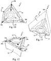
- a cutting insert 2 according to a first modification is shown, in which in addition to three cutting corners 28a, 28b which can be used for cutting, a further corner 29 is also provided, in particular in FIG Fig. 10 you can see.
- a first cutting corner 28a differs from a second cutting corner 28b in the configuration of the chip-guiding structures 22a and 22b formed on the upper side 22 in the region of the respective cutting corner 28a, 28b, in particular in FIGS 10 and FIG. 12 you can see.
- the cutting corners additionally differ in the corner angle and in the corner radius, under which the cutting corners are formed.
- a cutting insert 2 according to a second modification is shown in which a first cutting corner 28a and a second cutting corner 28b differ in the material from which they are formed.
- the cutting corners 28a, 28b all have the same corner angle ⁇ 1 and the same corner radius, but that Material of the cutting corners is different from each other.
- the lace insert 2 may be made of cemented carbide and the second cutting edge 28b may be formed of another cemented carbide having different toughness, hardness, grain size, binder, etc. properties.
- the second cutting corner 28b can also be formed, for example, from another hard material such as, in particular, cermet, polycrystalline diamond (PCD), CVD diamond, CBN (cubic boron nitride) or a cutting ceramic.
- the second cutting corner 28b may, for example, also be provided with a different coating than the first cutting corner 28a.
- two different cutting corners 28a and 28b are shown, eg more than two different cutting corners 28 can be provided and / or the cutting corners 28a, 28b can also differ from each other in further properties.
- FIGS. 15 and 16 There is shown a replaceable cutting insert 2 according to a third modification, in which the different cutting corners are formed for different machining operations.
- a first cutting corner 28a is, as in the previously described embodiments, formed as a "normal" cutting corner for, for example, longitudinal turning as a machining operation.
- a second cutting corner 28b is formed in the third modification as a cutting corner for piercing a groove.
- a third cutting corner 28c is formed in the third modification as a cutting corner for threading.
- a first cutting corner 28a is referred to as a "normal" cutting edge for For example, longitudinal turning trained and a second cutting edge 28b as a cutting corner for piercing.
- a third cutting corner 28c is likewise designed as a "normal” cutting corner, but which has a different corner angle than the first cutting corner 28a.
- the basic shape of the cutting insert 2 according to the fourth modification is different from the basic shape of the cutting insert 2 according to the third modification, as in FIGS FIGS. 17 and 18 you can see.
- a fifth modification of a cutting insert 2, which can be used in the described method is in the FIGS. 19 and 20 shown.
- the cutting insert 2 in turn has a total of three cutting corners 28a, 28b, 28c that can be used for turning, which in this case are, for example, identical to one another.
- the cutting insert 2 has in this modification in supervision the shape of a three-pointed star.
- the cutting corners can also be provided with different reinforcing chamfers, for example, which extend in each case at least in the region of the cutting corner and the adjoining cutting edge sections.
- these reinforcing chamfers can differ in their width (measured perpendicular to the cutting edge) or in their angle (measured with respect to a plane perpendicular to the main extension direction of the upper side 22).
- the different cutting corners can be used for example for turning various materials or for turning with different cutting parameters. It should be noted that, for example, different such Verstärkungsfasen not on in the FIGS. 19 and 20 shown basic shape of the cutting insert 2 are limited, but also with other basic shapes and in combination with other differences between the cutting corners 28a, 28b, 28c can be provided.
- the cutting insert 2 has an overall substantially triangular shape, in which the cutting corners all have the same corner angle.
- a first cutting corner 28a is formed with a small corner radius for eg a finishing machining, whereas the other cutting corners are formed as second cutting corners 28b with a larger corner radius for eg roughing.
- the anti-rotation elements and centering elements are shown on the underside 21 of the cutting insert 2, these elements may also be preferably provided in the modifications.
Landscapes
- Engineering & Computer Science (AREA)
- Mechanical Engineering (AREA)
- Milling Processes (AREA)
- Cutting Tools, Boring Holders, And Turrets (AREA)
- Turning (AREA)
Priority Applications (12)
| Application Number | Priority Date | Filing Date | Title |
|---|---|---|---|
| PL17002075T PL3501701T3 (pl) | 2017-12-22 | 2017-12-22 | System narzędziowy i sposób obróbki za pomocą toczenia |
| ES17002075T ES2815542T3 (es) | 2017-12-22 | 2017-12-22 | Sistema de herramientas y procedimiento de torneado |
| EP17002075.4A EP3501701B1 (fr) | 2017-12-22 | 2017-12-22 | Système d'outillage et procédé d'usinage par tournage |
| KR1020207018246A KR102394737B1 (ko) | 2017-12-22 | 2018-11-20 | 선삭을 위한 공구 시스템 및 방법 |
| RU2020120011A RU2743824C1 (ru) | 2017-12-22 | 2018-11-20 | Инструментальная система и способ токарной обработки |
| PCT/EP2018/081849 WO2019120824A1 (fr) | 2017-12-22 | 2018-11-20 | Système d'outil et procédé d'usinage par tournage |
| JP2020533613A JP7198821B2 (ja) | 2017-12-22 | 2018-11-20 | 工具システム及び旋削方法 |
| IL275082A IL275082B2 (en) | 2017-12-22 | 2018-11-20 | Tool system and method for turning |
| MX2020006618A MX2020006618A (es) | 2017-12-22 | 2018-11-20 | Sistema de herramienta y metodo para giro. |
| US16/956,694 US11396051B2 (en) | 2017-12-22 | 2018-11-20 | Tool system and method for turning |
| CN201880081219.5A CN111565874B (zh) | 2017-12-22 | 2018-11-20 | 用于车削的刀具系统和方法 |
| US17/717,704 US11806791B2 (en) | 2017-12-22 | 2022-04-11 | Method for turning a workpiece with a tool system |
Applications Claiming Priority (1)
| Application Number | Priority Date | Filing Date | Title |
|---|---|---|---|
| EP17002075.4A EP3501701B1 (fr) | 2017-12-22 | 2017-12-22 | Système d'outillage et procédé d'usinage par tournage |
Publications (2)
| Publication Number | Publication Date |
|---|---|
| EP3501701A1 true EP3501701A1 (fr) | 2019-06-26 |
| EP3501701B1 EP3501701B1 (fr) | 2020-07-29 |
Family
ID=60915136
Family Applications (1)
| Application Number | Title | Priority Date | Filing Date |
|---|---|---|---|
| EP17002075.4A Active EP3501701B1 (fr) | 2017-12-22 | 2017-12-22 | Système d'outillage et procédé d'usinage par tournage |
Country Status (11)
| Country | Link |
|---|---|
| US (2) | US11396051B2 (fr) |
| EP (1) | EP3501701B1 (fr) |
| JP (1) | JP7198821B2 (fr) |
| KR (1) | KR102394737B1 (fr) |
| CN (1) | CN111565874B (fr) |
| ES (1) | ES2815542T3 (fr) |
| IL (1) | IL275082B2 (fr) |
| MX (1) | MX2020006618A (fr) |
| PL (1) | PL3501701T3 (fr) |
| RU (1) | RU2743824C1 (fr) |
| WO (1) | WO2019120824A1 (fr) |
Cited By (5)
| Publication number | Priority date | Publication date | Assignee | Title |
|---|---|---|---|---|
| US20210008635A1 (en) * | 2018-03-08 | 2021-01-14 | Ab Sandvik Coromant | Turning tool and turning method for cnc-machines |
| EP3838455A1 (fr) * | 2019-12-17 | 2021-06-23 | Ceratizit Austria Gesellschaft m.b.H. | Système d'outil |
| EP3536428B1 (fr) | 2018-03-08 | 2022-08-10 | AB Sandvik Coromant | Procédé de tournage pour tour commandée par ordinateur et outil de tournage |
| EP3536425B1 (fr) | 2018-03-08 | 2023-08-16 | AB Sandvik Coromant | Procédé de tournage pour un tour commandée par ordinateur |
| EP4286079A1 (fr) | 2022-06-02 | 2023-12-06 | CERATIZIT Austria Gesellschaft m.b.H. | Système d'outil et procédé pour l'usinage d'une pièce utilisant ce système |
Families Citing this family (9)
| Publication number | Priority date | Publication date | Assignee | Title |
|---|---|---|---|---|
| PL3501701T3 (pl) * | 2017-12-22 | 2021-01-11 | Ceratizit Austria Gesellschaft M.B.H. | System narzędziowy i sposób obróbki za pomocą toczenia |
| KR102524260B1 (ko) * | 2018-10-10 | 2023-04-20 | 스미또모 덴꼬오 하드메탈 가부시끼가이샤 | 절삭 인서트 및 절삭 공구 |
| EP3738697B1 (fr) * | 2019-05-16 | 2023-02-22 | AB Sandvik Coromant | Outil tournant de découpe de métal |
| EP3738698B1 (fr) * | 2019-05-16 | 2022-11-02 | AB Sandvik Coromant | Plaquette de tournage pour la coupe des métaux, outil de coupe et procédé d'usinage d'une pièce métallique |
| JP7396140B2 (ja) * | 2020-03-18 | 2023-12-12 | 三菱マテリアル株式会社 | ねじ切り切削用インサートおよびねじ切り切削用刃先交換式バイト |
| EP4015118A1 (fr) * | 2020-12-15 | 2022-06-22 | AB Sandvik Coromant | Outil tournant de découpe de métal |
| US11534838B1 (en) | 2021-06-08 | 2022-12-27 | Iscar, Ltd. | Indexable lay-down cutting insert having a central body portion and three circumferentially spaced cutting portions, and cutting tool |
| EP4371684A1 (fr) | 2022-11-18 | 2024-05-22 | CERATIZIT Austria Gesellschaft m.b.H. | Procédé de tournage |
| CN117047148A (zh) * | 2023-09-22 | 2023-11-14 | 深圳市鑫明辉钻石刀具有限公司 | 一种组装式的机床刀具结构 |
Citations (4)
| Publication number | Priority date | Publication date | Assignee | Title |
|---|---|---|---|---|
| WO2004022270A1 (fr) * | 2002-09-03 | 2004-03-18 | Kennametal Inc. | Porte-outil |
| EP1415742A1 (fr) * | 2002-10-31 | 2004-05-06 | Sandvik Aktiebolag | Outil indexable pour usinage par enlèvement de copeaux |
| EP1260294B1 (fr) | 2001-05-18 | 2005-07-06 | CERATIZIT Austria Gesellschaft m.b.H. | Méthode et dispositif de tournage |
| US20110142562A1 (en) * | 2009-12-14 | 2011-06-16 | Dan Alexander Sturges | Method and System including a Horizontal Turning Head and Turning Bar for a Milling Machine |
Family Cites Families (51)
| Publication number | Priority date | Publication date | Assignee | Title |
|---|---|---|---|---|
| US1629667A (en) * | 1926-10-15 | 1927-05-24 | James D Knipple | Metal-cutting tool |
| US3274862A (en) * | 1965-04-12 | 1966-09-27 | Galaxy Boring Company | Boring bar |
| US3629919A (en) * | 1969-09-17 | 1971-12-28 | David J Trevarrow Jr | Tool and tool holder assembly |
| US4209047A (en) * | 1978-06-28 | 1980-06-24 | Weill Theodore C | Debarker toe assembly |
| US4621955A (en) * | 1984-04-16 | 1986-11-11 | Briese Leonard A | Cone shaped cutting insert |
| JPH01166003U (fr) | 1988-05-14 | 1989-11-21 | ||
| SU1618510A1 (ru) * | 1988-06-06 | 1991-01-07 | Владимирский политехнический институт | Многогранна режуща пластина |
| SU1600192A1 (ru) * | 1988-08-22 | 1995-03-10 | Дзержинский филиал Ленинградского научно-исследовательского и конструкторского института химического машиностроения | Инструмент для получения полых кольцевых изделий из полимерного материала |
| SU1774902A1 (ru) | 1991-01-09 | 1992-11-07 | Плeckob Bлaдиmиp Гehhaдьebич | Cmehhaя mhoгoгpahhaя плactиha |
| RU2039636C1 (ru) * | 1992-06-05 | 1995-07-20 | Акционерное общество открытого типа специального машиностроения и металлургии "Мотовилихинские заводы" | Узел режущего инструмента |
| EP0693984B1 (fr) * | 1993-04-14 | 1997-08-27 | Zettl Gmbh Cnc Präzisions- Und Sonderwerkzeuge | Outil de coupe |
| US5924826A (en) * | 1994-04-27 | 1999-07-20 | Sandvik Ab | Cutting insert mounted on holder by rib-and-groove coupling |
| SE509363C2 (sv) * | 1995-09-25 | 1999-01-18 | Sandvik Ab | Fastspänningsanordning fjör skärplattor samt skärplatta avsedd för dylik anordning |
| SE511390C2 (sv) * | 1997-03-05 | 1999-09-20 | Sandvik Ab | Anordning vid fastspänning av skärplattor för skärande metallbearbetning |
| SE509540C2 (sv) * | 1997-06-30 | 1999-02-08 | Seco Tools Ab | Verktyg |
| JP3402187B2 (ja) | 1998-03-06 | 2003-04-28 | 三菱マテリアル株式会社 | スローアウェイチップ及びスローアウェイ式切削工具 |
| SE9803111L (sv) | 1998-06-15 | 2000-03-16 | Seco Tools Ab | Metod |
| DE10009721A1 (de) * | 2000-03-01 | 2001-09-06 | Komet Stahlhalter Werkzeuge | Maschinenreibahle und Reibkopf für eine Maschinenreibahle |
| NO319690B1 (no) * | 2001-01-23 | 2005-09-05 | Teeness Asa | Skjaerhode for verktoymaskiner |
| DE10339518A1 (de) * | 2002-09-09 | 2004-03-18 | Komet Präzisionswerkzeuge Robert Breuning Gmbh | Bohrwerkzeug mit Wechselschneidplatten sowie Wechselschneidplatten für ein solches Bohrwerkzeug |
| SE526255C2 (sv) | 2003-03-14 | 2005-08-09 | Sandvik Intellectual Property | Verktyg och indexerbart skär för finsvarvning av rotationssymmetriska spår i arbetsstycken |
| US7156006B2 (en) * | 2003-09-02 | 2007-01-02 | Kennametal Inc. | Method and assembly for rotating a cutting insert during a turning operation and inserts used therein |
| US8573901B2 (en) * | 2003-09-02 | 2013-11-05 | Kennametal Inc. | Assembly for rotating a cutting insert during a turning operation and inserts used therein |
| US7325471B2 (en) | 2004-09-07 | 2008-02-05 | Kennametal Inc. | Toolholder and cutting insert for a toolholder assembly |
| SE528811C2 (sv) * | 2005-03-16 | 2007-02-20 | Sandvik Intellectual Property | Skär och verktyg för spånavskiljande bearbetning med vinklade ingreppsmedel, samt tillsats för dylika verktyg |
| JP4852301B2 (ja) | 2005-11-17 | 2012-01-11 | 株式会社リコー | 画像形成装置及び支持機構 |
| DE102006035182A1 (de) * | 2006-07-29 | 2008-01-31 | Hartmetall-Werkzeugfabrik Paul Horn Gmbh | Werkzeugsystem |
| DE102006055277A1 (de) * | 2006-11-23 | 2008-05-29 | Hartmetall-Werkzeugfabrik Paul Horn Gmbh | Schneidplatte für ein Bearbeitungswerkzeug, insbesondere Drehwerkzeug |
| BRPI0809306A2 (pt) | 2007-03-23 | 2019-09-24 | Kennametal Inc | montagem e inserto de corte |
| DE102008027009B4 (de) * | 2008-06-06 | 2010-08-12 | Kennametal Inc. | Schneideinsatz für ein Zerspanungswerkzeug, sowie Werkzeugsitz und Schneidwerkzeug |
| RU85383U1 (ru) * | 2009-04-06 | 2009-08-10 | Государственное образовательное учреждение высшего профессионального образования "Костромской государственный технологический университет" | Сменная многогранная режущая пластина |
| IL199936A0 (en) | 2009-07-19 | 2010-04-15 | Iscar Ltd | Rotary cutting tool and cutting insert therefor |
| US9475132B2 (en) * | 2009-10-15 | 2016-10-25 | Sandvik, Inc. | Multiteeth indexable insert with locating means and material removal tool with same |
| DE102010054392A1 (de) * | 2010-12-07 | 2012-06-14 | Hartmetall-Werkzeugfabrik Paul Horn Gmbh | Schneidwerkzeug zur spanenden Bearbeitung eines Werkzeugs |
| IL211113A (en) * | 2011-02-08 | 2015-09-24 | Iscar Ltd | Cutting tools and a tool for him |
| EP2883636B1 (fr) | 2012-08-10 | 2023-08-02 | Sumitomo Electric Hardmetal Corp. | Outil de tournage sur tour |
| US9120154B2 (en) * | 2013-02-14 | 2015-09-01 | Iscar, Ltd. | Single-sided square-shaped indexable cutting insert and cutting tool |
| US9120156B2 (en) | 2013-03-26 | 2015-09-01 | Iscar, Ltd. | Rhombus-shaped indexable cutting insert and cutting tool |
| FR3004746B1 (fr) * | 2013-04-19 | 2015-05-15 | Diager | Plaquette de coupe |
| EP2805786B1 (fr) * | 2013-05-21 | 2019-07-10 | Pramet Tools, S.R.O. | Insert de découpe indexable présentant un creux de support latéral et un outil de fraisage |
| US9421615B2 (en) * | 2014-04-10 | 2016-08-23 | Iscar, Ltd. | Cutting tool and cutting insert having exactly four cutting portions therefor |
| EP3006140B1 (fr) | 2014-10-08 | 2017-04-19 | Sandvik Intellectual Property AB | Insert de tournage et outil de tournage |
| DE102016104960A1 (de) * | 2016-03-17 | 2017-09-21 | Hartmetall-Werkzeugfabrik Paul Horn Gmbh | Schneidplatte, Werkzeughalter und Werkzeug |
| DE102016109670A1 (de) * | 2016-05-25 | 2017-11-30 | Hartmetall-Werkzeugfabrik Paul Horn Gmbh | Schneidplatte und Werkzeug zur spanenden Bearbeitung |
| US11260458B2 (en) * | 2017-07-11 | 2022-03-01 | Kyocera Corporation | Cutting insert, cutting tool and method for manufacturing machined product |
| DE102017123786A1 (de) * | 2017-10-12 | 2019-04-18 | Hartmetall-Werkzeugfabrik Paul Horn Gmbh | Halter für ein Nutstoßwerkzeug |
| PL3501701T3 (pl) * | 2017-12-22 | 2021-01-11 | Ceratizit Austria Gesellschaft M.B.H. | System narzędziowy i sposób obróbki za pomocą toczenia |
| EP3536427B1 (fr) * | 2018-03-08 | 2022-08-17 | AB Sandvik Coromant | Procédé de tournage et outil de tournage pour machines cnc |
| JP6961900B2 (ja) * | 2019-05-15 | 2021-11-05 | 住友電工ハードメタル株式会社 | ボーリングホルダーおよび旋削工具 |
| EP3838455A1 (fr) * | 2019-12-17 | 2021-06-23 | Ceratizit Austria Gesellschaft m.b.H. | Système d'outil |
| JP7003389B1 (ja) * | 2021-04-28 | 2022-01-20 | 株式会社タンガロイ | 切削インサート及び切削工具 |
-
2017
- 2017-12-22 PL PL17002075T patent/PL3501701T3/pl unknown
- 2017-12-22 EP EP17002075.4A patent/EP3501701B1/fr active Active
- 2017-12-22 ES ES17002075T patent/ES2815542T3/es active Active
-
2018
- 2018-11-20 JP JP2020533613A patent/JP7198821B2/ja active Active
- 2018-11-20 KR KR1020207018246A patent/KR102394737B1/ko active Active
- 2018-11-20 IL IL275082A patent/IL275082B2/en unknown
- 2018-11-20 RU RU2020120011A patent/RU2743824C1/ru active
- 2018-11-20 US US16/956,694 patent/US11396051B2/en active Active
- 2018-11-20 MX MX2020006618A patent/MX2020006618A/es unknown
- 2018-11-20 WO PCT/EP2018/081849 patent/WO2019120824A1/fr not_active Ceased
- 2018-11-20 CN CN201880081219.5A patent/CN111565874B/zh active Active
-
2022
- 2022-04-11 US US17/717,704 patent/US11806791B2/en active Active
Patent Citations (4)
| Publication number | Priority date | Publication date | Assignee | Title |
|---|---|---|---|---|
| EP1260294B1 (fr) | 2001-05-18 | 2005-07-06 | CERATIZIT Austria Gesellschaft m.b.H. | Méthode et dispositif de tournage |
| WO2004022270A1 (fr) * | 2002-09-03 | 2004-03-18 | Kennametal Inc. | Porte-outil |
| EP1415742A1 (fr) * | 2002-10-31 | 2004-05-06 | Sandvik Aktiebolag | Outil indexable pour usinage par enlèvement de copeaux |
| US20110142562A1 (en) * | 2009-12-14 | 2011-06-16 | Dan Alexander Sturges | Method and System including a Horizontal Turning Head and Turning Bar for a Milling Machine |
Cited By (11)
| Publication number | Priority date | Publication date | Assignee | Title |
|---|---|---|---|---|
| US20210008635A1 (en) * | 2018-03-08 | 2021-01-14 | Ab Sandvik Coromant | Turning tool and turning method for cnc-machines |
| EP3536428B1 (fr) | 2018-03-08 | 2022-08-10 | AB Sandvik Coromant | Procédé de tournage pour tour commandée par ordinateur et outil de tournage |
| EP3536427B1 (fr) | 2018-03-08 | 2022-08-17 | AB Sandvik Coromant | Procédé de tournage et outil de tournage pour machines cnc |
| US11597017B2 (en) * | 2018-03-08 | 2023-03-07 | Ab Sandvik Coromant | Turning tool and turning method for CNC-machines |
| EP3536425B1 (fr) | 2018-03-08 | 2023-08-16 | AB Sandvik Coromant | Procédé de tournage pour un tour commandée par ordinateur |
| EP3536428B2 (fr) † | 2018-03-08 | 2026-03-25 | AB Sandvik Coromant | Procédé de tournage pour tour commandée par ordinateur et outil de tournage |
| EP3838455A1 (fr) * | 2019-12-17 | 2021-06-23 | Ceratizit Austria Gesellschaft m.b.H. | Système d'outil |
| WO2021121783A1 (fr) * | 2019-12-17 | 2021-06-24 | Ceratizit Austria Gesellschaft M.B.H. | Système d'outil |
| JP2023508849A (ja) * | 2019-12-17 | 2023-03-06 | セラティチット オーストリア ゲゼルシャフト ミット ベシュレンクテル ハフツング | ツールシステム |
| US12397354B2 (en) | 2019-12-17 | 2025-08-26 | Ceratizit Austria Gesellschaft M.B.H. | Tool system |
| EP4286079A1 (fr) | 2022-06-02 | 2023-12-06 | CERATIZIT Austria Gesellschaft m.b.H. | Système d'outil et procédé pour l'usinage d'une pièce utilisant ce système |
Also Published As
| Publication number | Publication date |
|---|---|
| US20200324345A1 (en) | 2020-10-15 |
| IL275082B2 (en) | 2024-01-01 |
| JP2021514858A (ja) | 2021-06-17 |
| IL275082A (en) | 2020-07-30 |
| KR20200119232A (ko) | 2020-10-19 |
| MX2020006618A (es) | 2020-09-14 |
| IL275082B1 (en) | 2023-09-01 |
| US11396051B2 (en) | 2022-07-26 |
| RU2743824C1 (ru) | 2021-02-26 |
| JP7198821B2 (ja) | 2023-01-04 |
| CN111565874A (zh) | 2020-08-21 |
| US20220234117A1 (en) | 2022-07-28 |
| KR102394737B1 (ko) | 2022-05-04 |
| EP3501701B1 (fr) | 2020-07-29 |
| PL3501701T3 (pl) | 2021-01-11 |
| CN111565874B (zh) | 2023-01-10 |
| WO2019120824A1 (fr) | 2019-06-27 |
| US11806791B2 (en) | 2023-11-07 |
| ES2815542T3 (es) | 2021-03-30 |
Similar Documents
| Publication | Publication Date | Title |
|---|---|---|
| EP3501701B1 (fr) | Système d'outillage et procédé d'usinage par tournage | |
| EP1184116B1 (fr) | Outil de fraisage et de perçage | |
| EP3107676B1 (fr) | Plaquette de coupe indexable et fraise | |
| DE60204559T2 (de) | Bohreinsatzgeometrie mit spanspaltender kerbe | |
| EP3188866B1 (fr) | Plaquette de coupe double face et outil de fraisage | |
| DE3037097C2 (de) | Vollbohrwerkzeug, insbesondere Spiralbohrer | |
| DE102004030238B4 (de) | Tangential-Wendeschneideinsatz und Fräswerkzeug | |
| AT14072U1 (de) | Doppelseitiger Frässchneideinsatz und Fräswerkzeug | |
| DE112016001367B4 (de) | Einsatz, Bohrer und Verfahren des Herstellens eines maschinell bearbeiteten Produkts unter Verwendung derselben | |
| DE112018005471B4 (de) | Schneideinsatz, schneidwerkzeug und verfahren zur herstellung eines maschinell bearbeiteten produkts | |
| DE10040612A1 (de) | Schneidplatte für drehende Werkzeuge | |
| AT12934U1 (de) | Schneideinsatz | |
| EP3996861B1 (fr) | Plaquette de coupe double face pour fraisage | |
| DE102012016660A1 (de) | Einlippenbohrer | |
| DE102012010318B4 (de) | Nutbildungseinsatz | |
| EP3414038B1 (fr) | Outil de perçage | |
| EP1742755B1 (fr) | Plaquette de coupe et outil pour usinage par enlevement de copeaux de surfaces de forage | |
| EP3077142B1 (fr) | Plaquette de coupe pour l'usinage au tour | |
| EP3223983B1 (fr) | Outil pour l'usinage par enlèvement de copeaux | |
| DE10339518A1 (de) | Bohrwerkzeug mit Wechselschneidplatten sowie Wechselschneidplatten für ein solches Bohrwerkzeug | |
| AT15965U1 (de) | Fräsverfahren | |
| DE112019003627T5 (de) | Schneideinsatz, schneidwerkzeug und verfahren zur herstellung eines maschinell bearbeiteten produkts | |
| DE2805670A1 (de) | Rotierendes schneidwerkzeug | |
| DE102009033508B4 (de) | Einlippenbohrer | |
| DE112016002854B4 (de) | Schneidwerkzeug und Verfahren zur Herstellung eines geschnittenen Werkstücks |
Legal Events
| Date | Code | Title | Description |
|---|---|---|---|
| PUAI | Public reference made under article 153(3) epc to a published international application that has entered the european phase |
Free format text: ORIGINAL CODE: 0009012 |
|
| STAA | Information on the status of an ep patent application or granted ep patent |
Free format text: STATUS: THE APPLICATION HAS BEEN PUBLISHED |
|
| AK | Designated contracting states |
Kind code of ref document: A1 Designated state(s): AL AT BE BG CH CY CZ DE DK EE ES FI FR GB GR HR HU IE IS IT LI LT LU LV MC MK MT NL NO PL PT RO RS SE SI SK SM TR |
|
| AX | Request for extension of the european patent |
Extension state: BA ME |
|
| STAA | Information on the status of an ep patent application or granted ep patent |
Free format text: STATUS: REQUEST FOR EXAMINATION WAS MADE |
|
| 17P | Request for examination filed |
Effective date: 20191210 |
|
| RBV | Designated contracting states (corrected) |
Designated state(s): AL AT BE BG CH CY CZ DE DK EE ES FI FR GB GR HR HU IE IS IT LI LT LU LV MC MK MT NL NO PL PT RO RS SE SI SK SM TR |
|
| GRAP | Despatch of communication of intention to grant a patent |
Free format text: ORIGINAL CODE: EPIDOSNIGR1 |
|
| STAA | Information on the status of an ep patent application or granted ep patent |
Free format text: STATUS: GRANT OF PATENT IS INTENDED |
|
| INTG | Intention to grant announced |
Effective date: 20200422 |
|
| GRAS | Grant fee paid |
Free format text: ORIGINAL CODE: EPIDOSNIGR3 |
|
| GRAA | (expected) grant |
Free format text: ORIGINAL CODE: 0009210 |
|
| STAA | Information on the status of an ep patent application or granted ep patent |
Free format text: STATUS: THE PATENT HAS BEEN GRANTED |
|
| AK | Designated contracting states |
Kind code of ref document: B1 Designated state(s): AL AT BE BG CH CY CZ DE DK EE ES FI FR GB GR HR HU IE IS IT LI LT LU LV MC MK MT NL NO PL PT RO RS SE SI SK SM TR |
|
| REG | Reference to a national code |
Ref country code: CH Ref legal event code: EP |
|
| REG | Reference to a national code |
Ref country code: DE Ref legal event code: R096 Ref document number: 502017006372 Country of ref document: DE |
|
| REG | Reference to a national code |
Ref country code: AT Ref legal event code: REF Ref document number: 1295211 Country of ref document: AT Kind code of ref document: T Effective date: 20200815 |
|
| REG | Reference to a national code |
Ref country code: IE Ref legal event code: FG4D Free format text: LANGUAGE OF EP DOCUMENT: GERMAN |
|
| REG | Reference to a national code |
Ref country code: CH Ref legal event code: NV Representative=s name: DENNEMEYER AG, CH |
|
| REG | Reference to a national code |
Ref country code: NL Ref legal event code: FP |
|
| REG | Reference to a national code |
Ref country code: LT Ref legal event code: MG4D |
|
| PG25 | Lapsed in a contracting state [announced via postgrant information from national office to epo] |
Ref country code: HR Free format text: LAPSE BECAUSE OF FAILURE TO SUBMIT A TRANSLATION OF THE DESCRIPTION OR TO PAY THE FEE WITHIN THE PRESCRIBED TIME-LIMIT Effective date: 20200729 Ref country code: FI Free format text: LAPSE BECAUSE OF FAILURE TO SUBMIT A TRANSLATION OF THE DESCRIPTION OR TO PAY THE FEE WITHIN THE PRESCRIBED TIME-LIMIT Effective date: 20200729 Ref country code: GR Free format text: LAPSE BECAUSE OF FAILURE TO SUBMIT A TRANSLATION OF THE DESCRIPTION OR TO PAY THE FEE WITHIN THE PRESCRIBED TIME-LIMIT Effective date: 20201030 Ref country code: PT Free format text: LAPSE BECAUSE OF FAILURE TO SUBMIT A TRANSLATION OF THE DESCRIPTION OR TO PAY THE FEE WITHIN THE PRESCRIBED TIME-LIMIT Effective date: 20201130 Ref country code: LT Free format text: LAPSE BECAUSE OF FAILURE TO SUBMIT A TRANSLATION OF THE DESCRIPTION OR TO PAY THE FEE WITHIN THE PRESCRIBED TIME-LIMIT Effective date: 20200729 Ref country code: SE Free format text: LAPSE BECAUSE OF FAILURE TO SUBMIT A TRANSLATION OF THE DESCRIPTION OR TO PAY THE FEE WITHIN THE PRESCRIBED TIME-LIMIT Effective date: 20200729 Ref country code: NO Free format text: LAPSE BECAUSE OF FAILURE TO SUBMIT A TRANSLATION OF THE DESCRIPTION OR TO PAY THE FEE WITHIN THE PRESCRIBED TIME-LIMIT Effective date: 20201029 Ref country code: BG Free format text: LAPSE BECAUSE OF FAILURE TO SUBMIT A TRANSLATION OF THE DESCRIPTION OR TO PAY THE FEE WITHIN THE PRESCRIBED TIME-LIMIT Effective date: 20201029 |
|
| PG25 | Lapsed in a contracting state [announced via postgrant information from national office to epo] |
Ref country code: IS Free format text: LAPSE BECAUSE OF FAILURE TO SUBMIT A TRANSLATION OF THE DESCRIPTION OR TO PAY THE FEE WITHIN THE PRESCRIBED TIME-LIMIT Effective date: 20201129 Ref country code: LV Free format text: LAPSE BECAUSE OF FAILURE TO SUBMIT A TRANSLATION OF THE DESCRIPTION OR TO PAY THE FEE WITHIN THE PRESCRIBED TIME-LIMIT Effective date: 20200729 Ref country code: RS Free format text: LAPSE BECAUSE OF FAILURE TO SUBMIT A TRANSLATION OF THE DESCRIPTION OR TO PAY THE FEE WITHIN THE PRESCRIBED TIME-LIMIT Effective date: 20200729 |
|
| REG | Reference to a national code |
Ref country code: ES Ref legal event code: FG2A Ref document number: 2815542 Country of ref document: ES Kind code of ref document: T3 Effective date: 20210330 |
|
| PG25 | Lapsed in a contracting state [announced via postgrant information from national office to epo] |
Ref country code: DK Free format text: LAPSE BECAUSE OF FAILURE TO SUBMIT A TRANSLATION OF THE DESCRIPTION OR TO PAY THE FEE WITHIN THE PRESCRIBED TIME-LIMIT Effective date: 20200729 Ref country code: RO Free format text: LAPSE BECAUSE OF FAILURE TO SUBMIT A TRANSLATION OF THE DESCRIPTION OR TO PAY THE FEE WITHIN THE PRESCRIBED TIME-LIMIT Effective date: 20200729 Ref country code: SM Free format text: LAPSE BECAUSE OF FAILURE TO SUBMIT A TRANSLATION OF THE DESCRIPTION OR TO PAY THE FEE WITHIN THE PRESCRIBED TIME-LIMIT Effective date: 20200729 Ref country code: EE Free format text: LAPSE BECAUSE OF FAILURE TO SUBMIT A TRANSLATION OF THE DESCRIPTION OR TO PAY THE FEE WITHIN THE PRESCRIBED TIME-LIMIT Effective date: 20200729 |
|
| REG | Reference to a national code |
Ref country code: DE Ref legal event code: R097 Ref document number: 502017006372 Country of ref document: DE |
|
| PG25 | Lapsed in a contracting state [announced via postgrant information from national office to epo] |
Ref country code: AL Free format text: LAPSE BECAUSE OF FAILURE TO SUBMIT A TRANSLATION OF THE DESCRIPTION OR TO PAY THE FEE WITHIN THE PRESCRIBED TIME-LIMIT Effective date: 20200729 |
|
| PLBE | No opposition filed within time limit |
Free format text: ORIGINAL CODE: 0009261 |
|
| STAA | Information on the status of an ep patent application or granted ep patent |
Free format text: STATUS: NO OPPOSITION FILED WITHIN TIME LIMIT |
|
| PG25 | Lapsed in a contracting state [announced via postgrant information from national office to epo] |
Ref country code: SK Free format text: LAPSE BECAUSE OF FAILURE TO SUBMIT A TRANSLATION OF THE DESCRIPTION OR TO PAY THE FEE WITHIN THE PRESCRIBED TIME-LIMIT Effective date: 20200729 |
|
| 26N | No opposition filed |
Effective date: 20210430 |
|
| PG25 | Lapsed in a contracting state [announced via postgrant information from national office to epo] |
Ref country code: SI Free format text: LAPSE BECAUSE OF FAILURE TO SUBMIT A TRANSLATION OF THE DESCRIPTION OR TO PAY THE FEE WITHIN THE PRESCRIBED TIME-LIMIT Effective date: 20200729 Ref country code: MC Free format text: LAPSE BECAUSE OF FAILURE TO SUBMIT A TRANSLATION OF THE DESCRIPTION OR TO PAY THE FEE WITHIN THE PRESCRIBED TIME-LIMIT Effective date: 20200729 |
|
| REG | Reference to a national code |
Ref country code: BE Ref legal event code: MM Effective date: 20201231 |
|
| PG25 | Lapsed in a contracting state [announced via postgrant information from national office to epo] |
Ref country code: LU Free format text: LAPSE BECAUSE OF NON-PAYMENT OF DUE FEES Effective date: 20201222 Ref country code: IE Free format text: LAPSE BECAUSE OF NON-PAYMENT OF DUE FEES Effective date: 20201222 |
|
| PG25 | Lapsed in a contracting state [announced via postgrant information from national office to epo] |
Ref country code: MT Free format text: LAPSE BECAUSE OF FAILURE TO SUBMIT A TRANSLATION OF THE DESCRIPTION OR TO PAY THE FEE WITHIN THE PRESCRIBED TIME-LIMIT Effective date: 20200729 Ref country code: CY Free format text: LAPSE BECAUSE OF FAILURE TO SUBMIT A TRANSLATION OF THE DESCRIPTION OR TO PAY THE FEE WITHIN THE PRESCRIBED TIME-LIMIT Effective date: 20200729 |
|
| PG25 | Lapsed in a contracting state [announced via postgrant information from national office to epo] |
Ref country code: MK Free format text: LAPSE BECAUSE OF FAILURE TO SUBMIT A TRANSLATION OF THE DESCRIPTION OR TO PAY THE FEE WITHIN THE PRESCRIBED TIME-LIMIT Effective date: 20200729 |
|
| PG25 | Lapsed in a contracting state [announced via postgrant information from national office to epo] |
Ref country code: BE Free format text: LAPSE BECAUSE OF NON-PAYMENT OF DUE FEES Effective date: 20201231 |
|
| PGFP | Annual fee paid to national office [announced via postgrant information from national office to epo] |
Ref country code: CH Payment date: 20250101 Year of fee payment: 8 |
|
| REG | Reference to a national code |
Ref country code: CH Ref legal event code: U11 Free format text: ST27 STATUS EVENT CODE: U-0-0-U10-U11 (AS PROVIDED BY THE NATIONAL OFFICE) Effective date: 20260101 |
|
| PGFP | Annual fee paid to national office [announced via postgrant information from national office to epo] |
Ref country code: DE Payment date: 20251211 Year of fee payment: 9 |
|
| PGFP | Annual fee paid to national office [announced via postgrant information from national office to epo] |
Ref country code: GB Payment date: 20251219 Year of fee payment: 9 |
|
| PGFP | Annual fee paid to national office [announced via postgrant information from national office to epo] |
Ref country code: AT Payment date: 20251222 Year of fee payment: 9 |
|
| PGFP | Annual fee paid to national office [announced via postgrant information from national office to epo] |
Ref country code: IT Payment date: 20251223 Year of fee payment: 9 |
|
| PGFP | Annual fee paid to national office [announced via postgrant information from national office to epo] |
Ref country code: FR Payment date: 20251229 Year of fee payment: 9 Ref country code: NL Payment date: 20251219 Year of fee payment: 9 |
|
| PGFP | Annual fee paid to national office [announced via postgrant information from national office to epo] |
Ref country code: TR Payment date: 20251217 Year of fee payment: 9 |
|
| PGFP | Annual fee paid to national office [announced via postgrant information from national office to epo] |
Ref country code: CZ Payment date: 20251218 Year of fee payment: 9 |
|
| PGFP | Annual fee paid to national office [announced via postgrant information from national office to epo] |
Ref country code: PL Payment date: 20251212 Year of fee payment: 9 |
|
| PGFP | Annual fee paid to national office [announced via postgrant information from national office to epo] |
Ref country code: ES Payment date: 20260130 Year of fee payment: 9 |