EP3830517B1 - Procédé et dispositif de reconnaissance et d'analyse de défauts de surface d'objets tridimensionnels présentant une surface réfléchissante, en particulier de carrosseries de véhicule automobile - Google Patents
Procédé et dispositif de reconnaissance et d'analyse de défauts de surface d'objets tridimensionnels présentant une surface réfléchissante, en particulier de carrosseries de véhicule automobile Download PDFInfo
- Publication number
- EP3830517B1 EP3830517B1 EP19748656.6A EP19748656A EP3830517B1 EP 3830517 B1 EP3830517 B1 EP 3830517B1 EP 19748656 A EP19748656 A EP 19748656A EP 3830517 B1 EP3830517 B1 EP 3830517B1
- Authority
- EP
- European Patent Office
- Prior art keywords
- identified
- illumination
- pixels
- images
- surface defects
- Prior art date
- Legal status (The legal status is an assumption and is not a legal conclusion. Google has not performed a legal analysis and makes no representation as to the accuracy of the status listed.)
- Active
Links
Images


Classifications
-
- G—PHYSICS
- G01—MEASURING; TESTING
- G01B—MEASURING LENGTH, THICKNESS OR SIMILAR LINEAR DIMENSIONS; MEASURING ANGLES; MEASURING AREAS; MEASURING IRREGULARITIES OF SURFACES OR CONTOURS
- G01B11/00—Measuring arrangements characterised by the use of optical techniques
- G01B11/30—Measuring arrangements characterised by the use of optical techniques for measuring roughness or irregularity of surfaces
- G01B11/306—Measuring arrangements characterised by the use of optical techniques for measuring roughness or irregularity of surfaces for measuring evenness
-
- G—PHYSICS
- G01—MEASURING; TESTING
- G01B—MEASURING LENGTH, THICKNESS OR SIMILAR LINEAR DIMENSIONS; MEASURING ANGLES; MEASURING AREAS; MEASURING IRREGULARITIES OF SURFACES OR CONTOURS
- G01B11/00—Measuring arrangements characterised by the use of optical techniques
- G01B11/24—Measuring arrangements characterised by the use of optical techniques for measuring contours or curvatures
- G01B11/25—Measuring arrangements characterised by the use of optical techniques for measuring contours or curvatures by projecting a pattern, e.g. one or more lines, moiré fringes on the object
- G01B11/2513—Measuring arrangements characterised by the use of optical techniques for measuring contours or curvatures by projecting a pattern, e.g. one or more lines, moiré fringes on the object with several lines being projected in more than one direction, e.g. grids, patterns
-
- G—PHYSICS
- G01—MEASURING; TESTING
- G01B—MEASURING LENGTH, THICKNESS OR SIMILAR LINEAR DIMENSIONS; MEASURING ANGLES; MEASURING AREAS; MEASURING IRREGULARITIES OF SURFACES OR CONTOURS
- G01B11/00—Measuring arrangements characterised by the use of optical techniques
- G01B11/24—Measuring arrangements characterised by the use of optical techniques for measuring contours or curvatures
- G01B11/25—Measuring arrangements characterised by the use of optical techniques for measuring contours or curvatures by projecting a pattern, e.g. one or more lines, moiré fringes on the object
- G01B11/254—Projection of a pattern, viewing through a pattern, e.g. moiré
-
- G—PHYSICS
- G01—MEASURING; TESTING
- G01N—INVESTIGATING OR ANALYSING MATERIALS BY DETERMINING THEIR CHEMICAL OR PHYSICAL PROPERTIES
- G01N21/00—Investigating or analysing materials by the use of optical means, i.e. using sub-millimetre waves, infrared, visible or ultraviolet light
- G01N21/84—Systems specially adapted for particular applications
- G01N21/88—Investigating the presence of flaws or contamination
- G01N21/8806—Specially adapted optical and illumination features
-
- G—PHYSICS
- G01—MEASURING; TESTING
- G01N—INVESTIGATING OR ANALYSING MATERIALS BY DETERMINING THEIR CHEMICAL OR PHYSICAL PROPERTIES
- G01N21/00—Investigating or analysing materials by the use of optical means, i.e. using sub-millimetre waves, infrared, visible or ultraviolet light
- G01N21/84—Systems specially adapted for particular applications
- G01N21/88—Investigating the presence of flaws or contamination
- G01N21/8851—Scan or image signal processing specially adapted therefor, e.g. for scan signal adjustment, for detecting different kinds of defects, for compensating for structures, markings, edges
-
- G—PHYSICS
- G06—COMPUTING OR CALCULATING; COUNTING
- G06T—IMAGE DATA PROCESSING OR GENERATION, IN GENERAL
- G06T7/00—Image analysis
- G06T7/0002—Inspection of images, e.g. flaw detection
- G06T7/0004—Industrial image inspection
- G06T7/001—Industrial image inspection using an image reference approach
-
- G—PHYSICS
- G06—COMPUTING OR CALCULATING; COUNTING
- G06T—IMAGE DATA PROCESSING OR GENERATION, IN GENERAL
- G06T7/00—Image analysis
- G06T7/10—Segmentation; Edge detection
- G06T7/13—Edge detection
-
- G—PHYSICS
- G01—MEASURING; TESTING
- G01N—INVESTIGATING OR ANALYSING MATERIALS BY DETERMINING THEIR CHEMICAL OR PHYSICAL PROPERTIES
- G01N21/00—Investigating or analysing materials by the use of optical means, i.e. using sub-millimetre waves, infrared, visible or ultraviolet light
- G01N21/84—Systems specially adapted for particular applications
- G01N21/88—Investigating the presence of flaws or contamination
- G01N21/8806—Specially adapted optical and illumination features
- G01N2021/8809—Adjustment for highlighting flaws
-
- G—PHYSICS
- G01—MEASURING; TESTING
- G01N—INVESTIGATING OR ANALYSING MATERIALS BY DETERMINING THEIR CHEMICAL OR PHYSICAL PROPERTIES
- G01N21/00—Investigating or analysing materials by the use of optical means, i.e. using sub-millimetre waves, infrared, visible or ultraviolet light
- G01N21/84—Systems specially adapted for particular applications
- G01N21/88—Investigating the presence of flaws or contamination
- G01N21/8806—Specially adapted optical and illumination features
- G01N2021/8822—Dark field detection
- G01N2021/8825—Separate detection of dark field and bright field
-
- G—PHYSICS
- G01—MEASURING; TESTING
- G01N—INVESTIGATING OR ANALYSING MATERIALS BY DETERMINING THEIR CHEMICAL OR PHYSICAL PROPERTIES
- G01N21/00—Investigating or analysing materials by the use of optical means, i.e. using sub-millimetre waves, infrared, visible or ultraviolet light
- G01N21/84—Systems specially adapted for particular applications
- G01N21/88—Investigating the presence of flaws or contamination
- G01N21/8806—Specially adapted optical and illumination features
- G01N2021/8829—Shadow projection or structured background, e.g. for deflectometry
-
- G—PHYSICS
- G01—MEASURING; TESTING
- G01N—INVESTIGATING OR ANALYSING MATERIALS BY DETERMINING THEIR CHEMICAL OR PHYSICAL PROPERTIES
- G01N21/00—Investigating or analysing materials by the use of optical means, i.e. using sub-millimetre waves, infrared, visible or ultraviolet light
- G01N21/84—Systems specially adapted for particular applications
- G01N21/88—Investigating the presence of flaws or contamination
- G01N21/8851—Scan or image signal processing specially adapted therefor, e.g. for scan signal adjustment, for detecting different kinds of defects, for compensating for structures, markings, edges
- G01N2021/8854—Grading and classifying of flaws
- G01N2021/888—Marking defects
-
- G—PHYSICS
- G06—COMPUTING OR CALCULATING; COUNTING
- G06T—IMAGE DATA PROCESSING OR GENERATION, IN GENERAL
- G06T2207/00—Indexing scheme for image analysis or image enhancement
- G06T2207/20—Special algorithmic details
- G06T2207/20084—Artificial neural networks [ANN]
-
- G—PHYSICS
- G06—COMPUTING OR CALCULATING; COUNTING
- G06T—IMAGE DATA PROCESSING OR GENERATION, IN GENERAL
- G06T2207/00—Indexing scheme for image analysis or image enhancement
- G06T2207/30—Subject of image; Context of image processing
- G06T2207/30204—Marker
-
- G—PHYSICS
- G06—COMPUTING OR CALCULATING; COUNTING
- G06T—IMAGE DATA PROCESSING OR GENERATION, IN GENERAL
- G06T2207/00—Indexing scheme for image analysis or image enhancement
- G06T2207/30—Subject of image; Context of image processing
- G06T2207/30248—Vehicle exterior or interior
- G06T2207/30252—Vehicle exterior; Vicinity of vehicle
Definitions
- the present invention relates to a method for detecting and analyzing surface defects in three-dimensional objects with a reflective surface, in particular motor vehicle bodies, and to a device for detecting and analyzing surface defects in three-dimensional objects with a reflective surface, in particular motor vehicle bodies, in particular according to such a method, at least comprising: a first illumination device, in particular a lighting arc or a hand module, for projecting an illumination pattern onto a surface of the object; a camera, in particular activatable by a light barrier, for recording images in the form of a raster graphic made up of pixels; and a control and data analysis device.
- a first illumination device in particular a lighting arc or a hand module
- a camera in particular activatable by a light barrier, for recording images in the form of a raster graphic made up of pixels
- a control and data analysis device at least comprising: a first illumination device, in particular a lighting arc or a hand module, for projecting an illumination pattern onto a surface of the object; a
- From the DE 37 12 513 A1 is in this context a method and a device for detecting surface defects of an object, preferably for detecting of paint defects on the surface of a motor vehicle body, in which a strip of light is generated on the surface by means of a lighting system and is guided over the object, whereby its relative movement with respect to the surface is recorded step by step and used to determine surface defects.
- the EN 10 2010 015 566 A1 also discloses a method and system for measuring reflective surfaces, in which several patterns are generated on a luminous surface, which are reflected on the reflective surface and recorded with a sensor surface of a camera, whereby the coordinates of surface points of the surface being examined are determined from the recorded measurement data, from the known coordinates of the luminous and sensor surface and from the distance between the sensor and/or luminous surface and at least one support point arranged on the surface.
- the US 2014/201022 A1 also discloses a system for estimating surface damage to vehicles using 3D scans.
- the WO 2018/130421 A1 discloses a mobile device and a method for detecting and classifying damage to a vehicle body.
- a vehicle is moved through a lighting arc which projects a lighting pattern onto the vehicle body.
- video cameras record video images of the body and measure the distance between the surface of the body and the respective video camera as well as the speed of the vehicle moving through the arc.
- the distance measurements are first synchronized with the video image recording. Areas with possible damage are then located using known pattern recognition methods.
- the final identification of a spot on an examined surface as a surface defect can only be made - which is explicitly disadvantageous - if the surface area considered suspicious is found in several consecutive images.
- JP 2007 183 225 A A device for examining the surfaces of objects with smooth and highly reflective surfaces, such as car bodies, is described.
- the stripes of an illumination pattern projected onto the surface in question are evaluated.
- the actual defect identification is carried out by comparing it with corresponding projections of images on ideal, defect-free surfaces. At least two images are always required to identify surface defects: an image of the illumination pattern projected onto the surface to be examined and an image of a corresponding pattern projected onto an ideal, defect-free surface.
- the US 4 863 268 A1 discloses a method and a device for detecting surface defects on the surfaces of various objects, including vehicle bodies, and thereby further develops a recording technique that has already been described in a previous document ( US$ 4,629,319 ).
- the recording technique in question is characterized by the fact that light from a light source is radiated onto the surface to be examined, from there it hits a retroreflector and is thereby reflected in the direction from which it came, largely independent of the direction of incidence of the light, then hits the surface to be examined again, is reflected again and is finally recorded by the detector (which is positioned close to the light source).
- the DE 30 21 448 A1 discloses a method and an arrangement for detecting spatial deviations from a smooth plane on the mirrored or reflecting or diffusely scattering surface of objects. For this purpose, light rays from a light source reflected on said surfaces are detected and their brightness differences are evaluated. According to the disclosure, four possible light sources are possible: a luminous surface with a uniform brightness distribution, the light rays of which are directed onto the mirrored or reflecting or diffusely scattering surface via an optical Grid; or a luminous surface with uneven or periodic brightness or color distribution or a regular arrangement of several point-shaped radiators; or an image template with periodic or aperiodic, black-and-white or colored brightness structure that is projected onto the mirrored or reflective or diffusely scattering surface.
- the evaluation is then carried out by projecting the surface illuminated in this way onto the light-sensitive layer of a television camera and by evaluating the image signal from the television camera (video signal) with regard to the brightness or contrast differences of the illuminated surface.
- the video signal is quantized (digitized) and the information contained in the video signal, which comes from the grid structure of the lighting device superimposed on the image, is separated. Contours or surfaces can then be evaluated with regard to the presence of a surface defect.
- the present invention is based on the object of providing a method and an improved device for detecting and analyzing surface defects of three-dimensional objects with a reflective surface that are improved compared to the prior art, which can be used quickly, inexpensively and in a mobile manner and advantageously enable objective automated damage classification of surface defects, in particular hail damage to motor vehicle or aircraft bodies.
- the invention advantageously enables surface defects on the surface of three-dimensional objects with a reflective surface to be identified exclusively on the basis of two-dimensional image information using image processing algorithms. no "environmental parameters" are required, such as distances between the camera(s) and between the camera(s) and the object and/or its surface.
- complex geometric calculations, in particular triangulation calculations, as are regularly used in the prior art can advantageously be dispensed with.
- the solution according to the invention is therefore fast, robust and can be implemented in conjunction with a whole range of differently designed first lighting devices, which makes it particularly suitable for mobile applications, e.g. as a hand-held module.
- Advantageous embodiments increase the robustness of the method.
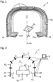
- Fig.1 shows an embodiment of a device 1 according to the invention for detecting and analyzing surface defects OF of three-dimensional objects 5 with a reflective surface 51 with a first illumination device 2 designed as an illumination arc in a perspective view.
- the inventive device 1 shown by way of example for detecting and analyzing surface defects OF of three-dimensional objects 5 with a reflective surface 51, in particular of motor vehicle bodies comprises at least a first illumination device 2 for projecting an illumination pattern 21 onto a surface 51 of the object 5; a camera 3, which can be activated in particular by a light barrier 11, for recording images in the form of a raster graphic made up of pixels; and a control and data analysis device 4. It is characterized in that the control and data analysis device 4 is set up to identify surface defects OF on the surface 51 of the object 5 using one or more images recorded by the camera 3 in the form of raster graphics made up of pixels using a two-dimensional raster coordinate system.
- the first lighting device 2 can be formed by a lighting arch with a frame 14, preferably an aluminum frame.
- the first lighting device 2 can also be designed as a hand-held module (not shown), which can preferably be in the form of a portable lamp, (organic) light-emitting diodes (LED/OLED), liquid crystal (LCD) or plasma displays.
- the lighting pattern 21 generated by the first lighting device 2 can be generated by regularly shading a continuous luminous surface, for example by an appropriately designed film arranged on the luminous surface.
- the first lighting device 2 can also be formed by at least one liquid crystal (LCD), (organic) light-emitting diodes (LED/OLED) or plasma display, which is either also shaded in regular sections and thereby a desired lighting pattern 21 is generated, or a lighting pattern 21 is projected directly in the form of an image projection onto the surface 51 of a three-dimensional object 5.
- LCD liquid crystal
- LED/OLED organic light-emitting diodes
- plasma display which is either also shaded in regular sections and thereby a desired lighting pattern 21 is generated, or a lighting pattern 21 is projected directly in the form of an image projection onto the surface 51 of a three-dimensional object 5.
- the embodiment of the device 1 shown comprises, for example, nine cameras 3, which are arranged in particular on the first lighting device 2, preferably, as shown here, on a frame 14 of a first lighting device 2 designed as a lighting arc.
- a calibration means 31 is shown by way of example, with the aid of which, preferably when the device 1 is put into operation, a calibration of one or more cameras 3 can advantageously be carried out.
- a calibration plate with evenly spaced points of known distance is shown as calibration means 31 by way of example.
- Fig.2 shows a further embodiment of the device 1 according to the invention with a first illumination device 2 designed as a lighting arc, as well as a three-dimensional object 5 to be examined in a front view.
- the first lighting device 2 can have at least two, preferably four, rollers 13 for moving the first lighting device 2
- the provision of rollers 13 on a first lighting device 2, which is designed in particular as a lighting arch, can advantageously increase the mobility of the device 1.
- the device 1 can be easily rolled onto or off a transport trailer using the rollers 13 and set up for use at any location.
- At least one light barrier 11 can advantageously be provided, which in Fig. 2 is shown as an example arranged on the frame 14 of the first lighting device 2 above the rollers 13.
- the at least one or more cameras 3 can advantageously be activated, in particular when a three-dimensional object 5, preferably a motor vehicle, moves through the first lighting device 2, in particular the lighting arc, and in doing so passes the light barrier 11.
- the light barrier 11 can of course also activate the at least one or more cameras 3 when the three-dimensional object 5 is stationary and the device 1, in particular the first lighting device 21, moves over the object 5.
- the movement of the device 1 relative to the object 5 can advantageously be realized with respect to the device 1 by the rollers 13 arranged on the first lighting device 2 and with respect to the three-dimensional object 5, in particular a motor vehicle, by its own drive including wheels.
- rails can also be provided on which the device 1 and/or the three-dimensional object 5 moves.
- the one or more cameras 3, the first 2 and second 201 lighting device, as well as the light barrier 11 can also communicate with the control and data analysis device 4, preferably via cable or wirelessly, for example via a WLAN or Bluetooth connection.
- the first lighting device 2 in particular the lighting arc, has at least one, preferably - as in Fig. 2 shown - comprise two mirrors 12, which are preferably arranged along a longitudinal axis LA adjacent to the floor on the lighting device 2, wherein the mirror or mirrors 12 are preferably arranged pivotably on the lighting device 2.
- Such mirrors 12 advantageously make it possible for lighting patterns 21 projected by the first lighting device 2 onto the surface 51 of the three-dimensional object 5 by mirroring, it is also advantageous to project onto areas of the surface 51 close to the ground and/or curved areas on which no illumination pattern 21 can be projected by direct projection.
- the first lighting device 2, in particular the lighting arc can also comprise at least one, preferably two, second lighting devices 201, which are preferably arranged along a longitudinal axis LA adjacent to the floor on the first lighting device 2, wherein the at least one second lighting device 201 is preferably arranged pivotably on the first lighting device 2 and is designed to project a lighting pattern 21, in particular a stripe pattern, onto a surface 51 of the object 5, in particular onto the surface 51 of the object 5 near the floor.
- the one or more second lighting devices 201 can be designed like the one or more first lighting devices 2, i.e.
- One or more such second illumination devices 201 can, like the mirrors 12, advantageously make it possible to project an illumination pattern 21 onto areas of the surface 51 that are close to the ground and/or curved, on which no illumination pattern 21 can be imaged with direct projection.
- different wavelengths i.e. different colors up to UV or infrared rays
- the type of one or more cameras 3 used is preferably selected according to the wavelength of light used, i.e. for example cameras 3 with a CCD detector for visible light, UV and/or infrared light.
- Fig.3 shows a part of an embodiment of a first lighting device 2 with three different lighting sections A, B, C.
- Lighting patterns 21, in particular strip patterns with smaller strip widths, as here for example from the lighting sections B and C are advantageously suitable for the detection and analysis of surface defects OF with a smaller diameter; whereas illumination patterns 21, in particular stripe patterns with comparatively larger stripe widths, as generated in particular by illumination section A, are advantageously suitable for the detection and analysis of surface defects OF with a larger diameter.
- a part of an embodiment of a first lighting device 2 is shown, as well as the lighting pattern 21 projected by it onto a three-dimensional object 5, here a motor vehicle body.
- surface defects OF By means of the method according to the invention for the detection and analysis of surface defects OF of three-dimensional objects 5 with a reflective surface 51, in particular of motor vehicle bodies, surface defects OF, as in Fig.4 shown by way of example, based on the evaluation of at least one image of an illumination pattern 21 projected by at least one first illumination device 2 onto at least a portion of the surface 51, recorded by at least one camera 3 in the form of a raster graphic of pixels, using a two-dimensional raster coordinate system.
- the illumination pattern 21 can preferably be a stripe pattern, in particular a stripe pattern with a sinusoidal intensity profile, wherein the stripe widths, as already shown in Fig.3 shown, can be differentiated from each other in sections (see lighting sections A, B, C).
- one or more images in the form of raster graphics made of pixels of at least a part of the surface 51 of the object 5 can be recorded advantageously by means of at least one camera 3.
- the (optimal) exposure time can be determined and set, in particular by means of a control and data analysis device 4, of the one camera 3 or several cameras 3 based on the color of the surface 51 of the object 5, in particular the color of the motor vehicle body.
- the one or more cameras 3 are calibrated with the aid of a calibration means 31, as in Fig.1 shown is calibrated.
- a region 511 of the recorded surface 51 of the object 5, onto which the illumination pattern 21 is projected is now identified within the recorded image(s), wherein the identified region 511 is assigned a two-dimensional grid coordinate system with x and y coordinates for each pixel.
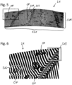
- Fig.5 shows an example of a raster graphic of such an identified region 511 of a part of a surface 51 of a three-dimensional object 5, here using the example of a hood of a motor vehicle.
- At least some of the pixels are assigned intensity values, in particular light-dark values.
- intensity values in particular light-dark values.
- a functional (mathematical) relationship is then established for the respective group of pixels identified as belonging together.
- the Fig.5 The light stripes 211 and dark stripes 212 shown can thereby advantageously be approximated in the form of mathematical curves, e.g. as a polynomial or spline.
- the first derivative of a found functional (mathematical) relationship is then determined and at least sections of the illumination pattern 21 projected onto the surface 51, in particular the stripes of a stripe pattern, in the image or images are classified based on the first derivative of a found functional (mathematical) relationship, in particular based on a slope of the function graph.
- Fig.7 are exemplary three light strips 211 classified in this way (horizontally hatched, diagonally hatched and checkered hatched) are shown, with each hatching corresponding, for example, to a specific gradient preferably within a predetermined area in the sense of a "neighborhood analysis”.
- surface defects OF are identified based on characteristic changes and/or a loss of the first derivative of a found functional (mathematical) relationship, in particular the slope of a function graph, in the classified sections, in particular in the stripes of a stripe pattern.
- Fig.6 shows an enlargement of the Fig.5 dashed framed section of the raster graphic, in which in turn is framed an area 512 with surface defect OF (bottom left) and an area 513 without surface defect OF, but change in the structure of the surface 51 (top right), where Fig.7 Finally, an increase in the Fig.6 shown area 512 with surface defect OF (framed lower left) with an identified and classified surface defect OF.
- the size of individual identified surface defects OF can also be determined by determining a center point of the respective surface defect OF and at least one extremum E spaced from the center point MP.
- a model function MF e.g. a circle or ellipse function
- the maximum or minimum of a found function graph can be used as the extremum E, for example.
- the at least one lighting device 2 and/or the at least one camera 3 can be moved relative to the three-dimensional object (5).
- the three-dimensional object 5 can also be moved relative to the at least one lighting device 2 and/or to the at least one camera 3.
- a motor vehicle can drive through a first lighting device designed as a lighting arc.
- several images in particular several images from several cameras 3, can then preferably be recorded.
- at least one marker M in particular four markers M, is arranged on the surface 51 of the object 5 and the position of the marker or markers M is determined within the recorded image or images.
- the determination of the position of one or more markers M within different recorded images can advantageously be used, preferably before starting a further surface analysis, to combine several images into a two-dimensional grid coordinate system, in particular when the object 5 to be examined, or its Surface 51 is larger than the illumination pattern 21 projected onto the surface 51 of the object 5.
- several images are advantageously recorded, in particular also by several cameras 3, which can then be advantageously combined with one another in a grid coordinate system based on position information of at least one marker M in the various images.
- surface defects OF identified in a method step are classified by a comparison with at least one model function MF, in particular with a circular function and/or ellipse function, and/or a pattern of already classified surface defects OF, characteristic changes and/or a loss of the first derivative of an already found functional (mathematical) relationship, and the measurement and/or evaluation data of surface defects OF classified in this way are stored in a database, in particular in a cloud database.
- identified surface defects OF can also be classified by a comparison with database entries, in particular with database entries of a database with measurement and/or evaluation data of already classified surface defects OF, and measurement and/or evaluation data of classified surface defects OF are stored in a database, in particular in a cloud database.
- the present invention relates to a method for detecting and analyzing surface defects OF of three-dimensional objects 5 with a reflective surface 51, in particular of motor vehicle bodies, in which the surface defects OF are identified based on the evaluation of at least one image of an illumination pattern 21 projected by at least one first illumination device 2 onto at least part of the surface 51, recorded by at least one camera 3 in the form of a raster graphic of pixels, using a two-dimensional raster coordinate system, and a device 1 for this purpose. It advantageously enables surface defects OF to be identified exclusively based on two-dimensional image information with the aid of image processing algorithms. to identify, whereby no "environmental parameters" are required and complex geometric calculations can advantageously be dispensed with.
- the solution according to the invention is therefore fast, robust and can be carried out in conjunction with differently designed first lighting devices 2, which makes it particularly suitable for mobile applications, e.g. as a hand-held module.
Landscapes
- Engineering & Computer Science (AREA)
- Physics & Mathematics (AREA)
- General Physics & Mathematics (AREA)
- Computer Vision & Pattern Recognition (AREA)
- Analytical Chemistry (AREA)
- Biochemistry (AREA)
- General Health & Medical Sciences (AREA)
- Chemical & Material Sciences (AREA)
- Immunology (AREA)
- Pathology (AREA)
- Life Sciences & Earth Sciences (AREA)
- Health & Medical Sciences (AREA)
- Theoretical Computer Science (AREA)
- Quality & Reliability (AREA)
- Signal Processing (AREA)
- Investigating Materials By The Use Of Optical Means Adapted For Particular Applications (AREA)
- Length Measuring Devices By Optical Means (AREA)
Claims (11)
- Procédé de reconnaissance et d'analyse de défauts de surface (OF) d'objets tridimensionnels (5) comprenant une surface réfléchissante (51), notamment de carrosseries de véhicule, avec lequel les défauts de surface (OF) sont identifiés à l'aide de l'interprétation d'au moins une image, enregistrée par au moins une caméra (3) sous la forme d'un graphique matriciel constitué de pixels, d'un motif d'éclairage (21), projeté par au moins un premier dispositif d'éclairage (2) sur au moins une partie de la surface (51), à l'aide d'un système de coordonnées en grille bidimensionnel,- une zone (511) de la surface (51) enregistrée de l'objet (5) sur laquelle est projeté le motif d'éclairage (21) étant identifiée à l'intérieur de la ou des images enregistrées ;- un système de coordonnées en grille bidimensionnel avec des coordonnées x et y pour chaque pixel étant attribué à la zone (511) identifiée ;- à l'intérieur de la zone (511) identifiée, à partir d'un point zéro du système de coordonnées en grille bidimensionnel, des valeurs d'intensité étant attribuées à au moins une partie des pixels ; et- au moins des portions du motif d'éclairage (21) projeté sur la surface (51) étant identifiées dans la ou les images au moyen de la détection des contours en partant de valeurs de départ préalablement spécifiées,- les pixels ayant des valeurs d'intensité égales ou similaires jusqu'à une valeur d'écart prédéterminée étant identifiés comme associés ;- une relation fonctionnelle pour le groupe respectif de pixels identifiés comme associés étant établie à l'aide d'un groupe de pixels identifiés comme associés ;- au moins des portions du motif d'éclairage (21) projeté sur la surface (51) dans la ou les images étant classifiées à l'aide de la première dérivée d'une relation fonctionnelle trouvée ;- et des défauts de surface (OF) étant identifiés à l'intérieur de la zone (511) identifiée dans les portions classifiées à l'aide de modifications caractéristiques et/ou d'une suppression de la première dérivée d'une relation fonctionnelle trouvée.
- Procédé selon la revendication 1, avec lequel le motif d'éclairage (21) est un motif à bandes, notamment un motif à bandes ayant une courbe d'intensité sinusoïdale.
- Procédé selon la revendication 1 ou 2, avec lequel une ou plusieurs images d'au moins une partie de la surface (51) de l'objet (5) sont enregistrées sous la forme de graphiques matriciels constitués de pixels au moyen d'au moins une caméra (3),- le temps d'exposition (optimal) de ladite caméra (3) ou des plusieurs caméras (3) étant de préférence déterminé et réglé, notamment après un réglage manuel ou automatisé de la mise au moins de ladite caméra (3) ou des plusieurs caméras (3), notamment au moyen d'un dispositif de commande et d'analyse de données (4), à l'aide de la couleur de la surface (51) de l'objet (5), notamment de la couleur de la carrosserie de véhicule ; et/ou- ladite ou les plusieurs caméras (3) étant calibrées à l'aide d'un moyen de calibrage (31).
- Procédé selon une ou plusieurs des revendications précédentes, avec lequel- à l'intérieur de la zone (511) identifiée, en partant d'un point zéro du système de coordonnées en grille bidimensionnel, des valeurs clair-foncé sont attribuées à au moins une partie des pixels ; et avec lequel- au moins des portions du motif d'éclairage (21) projeté sur la surface (51), notamment les bandes d'un motif à bandes, sont identifiées dans la ou les images au moyen de la détection des contours en partant de valeurs de départ préalablement spécifiées,- les pixels ayant des valeurs clair-foncé égales ou similaires jusqu'à une valeur d'écart prédéterminée étant identifiés comme associés.
- Procédé selon une ou plusieurs des revendications précédentes, avec lequel, pour chaque pixel d'un groupe de pixels identifiés comme associés, la première dérivée d'une relation fonctionnelle trouvée, notamment la pente d'un graphe de fonction trouvé, est déterminée.
- Procédé selon une ou plusieurs des revendications précédentes, avec lequel la taille des défauts de surface (OF) individuels identifiés est identifiée par détermination d'un point central du défaut de surface (OF) respectif et d'au moins une valeur extrême (E) espacée du point central (MP).
- Procédé selon une ou plusieurs des revendications précédentes, avec lequel au moins un marqueur (M), notamment quatre marqueurs (M) sont disposés sur la surface (51) de l'objet (5) et la position du ou des marqueurs (M) à l'intérieur de la ou des images enregistrées est déterminée.
- Procédé selon une ou plusieurs des revendications précédentes, avec lequel- l'au moins un premier dispositif d'éclairage (2) et/ou l'au moins une caméra (3) est déplacé par rapport à l'objet tridimensionnel (5) ; ou- avec lequel l'objet tridimensionnel (5) est déplacé par rapport à l'au moins un premier dispositif d'éclairage (2) et/ou l'au moins une caméra (3).
- Procédé selon une ou plusieurs des revendications précédentes, avec lequel- les défauts de surface (OF) identifiés sont classifiés par une comparaison avec au moins une fonction de modèle (MF), notamment avec une fonction de cercle et/ou une fonction d'ellipse, et/ou un modèle de défauts de surface (OF) déjà classifiés, des modifications caractéristiques et/ou une suppression de la première dérivée d'une relation (mathématique) fonctionnelle déjà trouvée, et les données de mesure et/ou d'interprétation des défauts de surface (OF) ainsi classifiés sont enregistrées dans une base de données, notamment une base de données en nuage ; et/ou- les défauts de surface (OF) identifiés sont classifiés par une comparaison avec des entrées de base de données, notamment avec des entrées de base de données d'une base de données comprenant des données de mesure et/ou d'interprétation des défauts de surface (OF) déjà classifiés, et les données de mesure et/ou d'interprétation des défauts de surface (OF) classifiés sont enregistrées dans une base de données, notamment une base de données en nuage.
- Arrangement (1) de reconnaissance et d'analyse de défauts de surface (OF) d'objets tridimensionnels (5) comprenant une surface réfléchissante (51), notamment de carrosseries de véhicule, notamment conformément à un procédé selon une ou plusieurs des revendications 1 à 9, comprenant au moins- un premier dispositif d'éclairage (2), notamment un arc d'éclairage ou un module manuel, destiné à la projection d'un motif d'éclairage (21) sur une surface (51) de l'objet (5) ;- une caméra (3), pouvant notamment être activée par une barrière photoélectrique (11), destinée à enregistrer des images sous la forme d'un graphique matriciel constitué de pixels ; et- un dispositif de commande et d'analyse de données (4) ;
caractérisé en ce que- le dispositif de commande et d'analyse de données (4) est conçu pour, à l'aide d'une ou de plusieurs images enregistrées au moyen de la caméra (3) sous la forme de graphiques matriciels constitués de pixels, identifier des défauts de surface (OF) sur la surface (51) de l'objet (5) à l'aide d'un système de coordonnées en grille bidimensionnel,- une zone (511) de la surface (51) enregistrée de l'objet (5) sur laquelle est projeté le motif d'éclairage (21) étant identifiée à l'intérieur de la ou des images enregistrées ;- un système de coordonnées en grille bidimensionnel avec des coordonnées x et y pour chaque pixel étant attribué à la zone (511) identifiée ;- à l'intérieur de la zone (511) identifiée, à partir d'un point zéro du système de coordonnées en grille bidimensionnel, des valeurs d'intensité étant attribuées à au moins une partie des pixels ; et- au moins des portions du motif d'éclairage (21) projeté sur la surface (51) étant identifiées dans la ou les images au moyen de la détection des contours en partant de valeurs de départ préalablement spécifiées,- les pixels ayant des valeurs d'intensité égales ou similaires jusqu'à une valeur d'écart prédéterminée étant identifiés comme associés ;- une relation fonctionnelle pour le groupe respectif de pixels identifiés comme associés étant établie à l'aide d'un groupe de pixels identifiés comme associés ;- au moins des portions du motif d'éclairage (21) projeté sur la surface (51) dans la ou les images étant classifiées à l'aide de la première dérivée d'une relation fonctionnelle trouvée ;- et des défauts de surface (OF) étant identifiés à l'intérieur de la zone (511) identifiée dans les portions classifiées à l'aide de modifications caractéristiques et/ou d'une suppression de la première dérivée d'une relation fonctionnelle trouvée. - Arrangement (1) selon la revendication 10, comprenant notamment un premier dispositif d'éclairage (2) réalisé sous la forme d'un arc d'éclairage mobile sur au moins deux, ou de préférence quatre rouleaux (13), caractérisé en ce- que le premier dispositif d'éclairage (2), notamment l'arc d'éclairage, comporte au moins un, de préférence deux miroirs (12), lesquels sont de préférence disposés sur le premier dispositif d'éclairage (2) le long d'un axe longitudinal (LA) voisin du sol,- l'au moins un miroir (12) étant de préférence monté pivotant sur le premier dispositif d'éclairage (2) et conçu pour projeter par réflexion un motif d'éclairage (21), notamment un motif à bandes du premier dispositif d'éclairage (2) sur une surface (51) de l'objet (5), notamment sur la surface (51) de l'objet (5) à proximité du sol ;
et/ou- que le premier dispositif d'éclairage (2), notamment l'arc d'éclairage, comporte au moins un, de préférence deux deuxièmes dispositifs d'éclairage (201), lesquels sont de préférence disposés sur le premier dispositif d'éclairage (2) le long d'un axe longitudinal (LA) voisin du sol,- le deuxième dispositif d'éclairage (201) étant de préférence monté pivotant sur le premier dispositif d'éclairage (2) et conçu pour projeter un motif d'éclairage (21), notamment un motif à bandes, sur une surface (51) de l'objet (5), notamment sur la surface (51) de l'objet (5) à proximité du sol.
Applications Claiming Priority (2)
| Application Number | Priority Date | Filing Date | Title |
|---|---|---|---|
| DE102018118602.9A DE102018118602B3 (de) | 2018-07-31 | 2018-07-31 | Verfahren und Vorrichtung zur Erkennung und Analyse von Oberflächenfehlern dreidimensionaler Objekte mit einer reflektierenden Oberfläche, insbesondere von Kraftfahrzeugkarosserien |
| PCT/DE2019/100655 WO2020025086A1 (fr) | 2018-07-31 | 2019-07-15 | Procédé et dispositif de reconnaissance et d'analyse de défauts de surface d'objets tridimensionnels présentant une surface réfléchissante, en particulier de carrosseries de véhicule automobile |
Publications (3)
| Publication Number | Publication Date |
|---|---|
| EP3830517A1 EP3830517A1 (fr) | 2021-06-09 |
| EP3830517C0 EP3830517C0 (fr) | 2024-09-11 |
| EP3830517B1 true EP3830517B1 (fr) | 2024-09-11 |
Family
ID=67514270
Family Applications (1)
| Application Number | Title | Priority Date | Filing Date |
|---|---|---|---|
| EP19748656.6A Active EP3830517B1 (fr) | 2018-07-31 | 2019-07-15 | Procédé et dispositif de reconnaissance et d'analyse de défauts de surface d'objets tridimensionnels présentant une surface réfléchissante, en particulier de carrosseries de véhicule automobile |
Country Status (6)
| Country | Link |
|---|---|
| US (1) | US11674907B2 (fr) |
| EP (1) | EP3830517B1 (fr) |
| AU (1) | AU2019312721B2 (fr) |
| CA (1) | CA3106398A1 (fr) |
| DE (2) | DE102018118602B3 (fr) |
| WO (1) | WO2020025086A1 (fr) |
Families Citing this family (14)
| Publication number | Priority date | Publication date | Assignee | Title |
|---|---|---|---|---|
| HUE065281T2 (hu) * | 2019-09-11 | 2024-05-28 | Proov Station | Gépjármû karosszériáján lévõ hibák detektálására szolgáló berendezés |
| WO2021151412A1 (fr) * | 2020-01-27 | 2021-08-05 | Jan Nabatian | Dispositif et procédé de détection automatique de dommages sur des véhicules |
| US20210375078A1 (en) * | 2020-05-28 | 2021-12-02 | Gm Cruise Holdings Llc | Automated vehicle body damage detection |
| DE102020120559A1 (de) | 2020-08-04 | 2022-02-10 | Bayerische Motoren Werke Aktiengesellschaft | Verfahren zum Bearbeiten wenigstens eines Defekts einer Oberfläche eines Bauteils, insbesondere in einem Bereich wenigstens eines Oberflächenmerkmals |
| US11828711B2 (en) * | 2020-10-09 | 2023-11-28 | Virtek Vision International Inc | Method and system for inspecting repair or assembly operations |
| DE102020131086A1 (de) * | 2020-11-24 | 2022-05-25 | Broetje-Automation Gmbh | Verfahren zum Bearbeiten eines Flugzeugstrukturbauteils |
| DE102020216401B3 (de) * | 2020-12-21 | 2022-05-19 | Siemens Aktiengesellschaft | Verfahren zur automatisierten Unterstützung einer Inspektion und/oder Zustandsüberwachung von Objekten |
| WO2022162417A1 (fr) * | 2021-01-26 | 2022-08-04 | Abb Schweiz Ag | Systèmes et procédés de détection de défaut de peinture à l'aide de l'apprentissage machine |
| FR3122489B1 (fr) * | 2021-04-28 | 2023-06-23 | Office Nat Detudes Rech Aerospatiales | Procédé pour estimer la géométrie d’une surface réfléchissante d’un objet |
| DE102021123880A1 (de) | 2021-09-15 | 2023-03-16 | Isra Vision Gmbh | Verfahren und Vorrichtung zur Erkennung von lokalen Fehlern auf einer spiegelnden Oberfläche |
| CN115236085A (zh) * | 2022-07-19 | 2022-10-25 | 中冶赛迪信息技术(重庆)有限公司 | 一种利用投射曲线识别表面质量的方法 |
| LU503215B1 (en) * | 2022-12-20 | 2024-06-20 | Virelux Inspection Systems Sarl | Dynamic single-period reflectometry scanner |
| DE102024115850A1 (de) * | 2024-06-06 | 2025-12-11 | SSI Schäfer AG | Automatische Regalinspektion in Hochregallagern |
| US12556675B1 (en) * | 2025-09-08 | 2026-02-17 | Antonio Stranges | Modular portable spherical scanning system |
Citations (5)
| Publication number | Priority date | Publication date | Assignee | Title |
|---|---|---|---|---|
| US5367378A (en) * | 1993-06-01 | 1994-11-22 | Industrial Technology Institute | Highlighted panel inspection |
| US5568258A (en) * | 1992-08-25 | 1996-10-22 | Asahi Glass Company Ltd. | Method and device for measuring distortion of a transmitting beam or a surface shape of a three-dimensional object |
| DE10006663B4 (de) * | 2000-02-15 | 2006-10-05 | Metronom Ag | Verfahren zur Vermessung von langwelligen Oberflächenstrukturen |
| EP1464920B1 (fr) * | 2003-04-03 | 2007-07-25 | Erwin Pristner | Dispositif pour détecter, déterminer et documenter les endommagements, en particulier les déformations de surfaces peintes causées par des évènements soudains |
| WO2019239307A1 (fr) * | 2018-06-12 | 2019-12-19 | Geico Spa | Procédé et installation de localisation de points sur une surface complexe dans l'espace |
Family Cites Families (19)
| Publication number | Priority date | Publication date | Assignee | Title |
|---|---|---|---|---|
| DE3021448A1 (de) | 1980-06-06 | 1981-12-24 | Siemens AG, 1000 Berlin und 8000 München | Verfahren und anordnung zur erfassung raeumlicher abweichungen von einer glatten ebene an oberflaechen von gegenstaenden |
| US4863268A (en) * | 1984-02-14 | 1989-09-05 | Diffracto Ltd. | Diffractosight improvements |
| DE3712513A1 (de) | 1987-04-13 | 1988-11-03 | Roth Electric Gmbh | Verfahren und vorrichtung zur erkennung von oberflaechenfehlern |
| US6462813B1 (en) * | 1996-04-12 | 2002-10-08 | Perceptron, Inc. | Surface defect inspection system and method |
| JPH109839A (ja) * | 1996-06-24 | 1998-01-16 | Nissan Motor Co Ltd | 表面欠陥検査装置 |
| DE19849802A1 (de) * | 1998-10-29 | 2000-05-04 | Volkswagen Ag | Lackfehlererkennung und Beseitigung |
| JP2007183225A (ja) | 2006-01-10 | 2007-07-19 | Toyota Motor Corp | 光照射装置、面形状検査システム、および面形状検査方法 |
| JP4685971B2 (ja) * | 2009-09-24 | 2011-05-18 | 株式会社ケー・デー・イー | 検査システム及び検査方法 |
| DE102010015566B4 (de) * | 2010-04-19 | 2013-10-02 | adomea GmbH | Verfahren und System zur Vermessung spiegelnder Oberflächen |
| US20130057678A1 (en) * | 2010-05-17 | 2013-03-07 | Ford Espana S.L. | Inspection system and method of defect detection on specular surfaces |
| US20140201022A1 (en) * | 2013-01-16 | 2014-07-17 | Andre Balzer | Vehicle damage processing and information system |
| FR3039276B1 (fr) * | 2015-07-23 | 2017-11-10 | Snecma | Procede de traitement et de controle d'une surface precontrainte |
| DE102015119240B3 (de) | 2015-11-09 | 2017-03-30 | ATENSOR Engineering and Technology Systems GmbH | Automatisches detektieren und robotergestütztes bearbeiten von oberflächendefekten |
| DE102016006780A1 (de) * | 2016-06-02 | 2017-12-07 | Eisenmann Se | Anlage zur optischen Überprüfung von Oberflächenbereichen von Gegenständen |
| EP3279864B1 (fr) * | 2016-08-05 | 2019-03-06 | Thomson Licensing | Procédé d'obtention de paramètres définissant un faisceau de pixels associé à un pixel d'un capteur d'images compris dans un dispositif optique |
| IT201700002416A1 (it) * | 2017-01-11 | 2018-07-11 | Autoscan Gmbh | Apparecchiatura mobile automatizzata per il rilevamento e la classificazione dei danni sulla carrozzeria |
| US10451558B1 (en) * | 2018-03-30 | 2019-10-22 | Dent Impressions, Inc. | Vehicle lighting |
| EP3715779B1 (fr) * | 2019-03-29 | 2022-10-19 | Fraunhofer-Gesellschaft zur Förderung der angewandten Forschung e.V. | Procédé et dispositif de détermination des déformations d'un objet |
| WO2021151412A1 (fr) * | 2020-01-27 | 2021-08-05 | Jan Nabatian | Dispositif et procédé de détection automatique de dommages sur des véhicules |
-
2018
- 2018-07-31 DE DE102018118602.9A patent/DE102018118602B3/de active Active
-
2019
- 2019-07-15 CA CA3106398A patent/CA3106398A1/fr active Pending
- 2019-07-15 AU AU2019312721A patent/AU2019312721B2/en active Active
- 2019-07-15 EP EP19748656.6A patent/EP3830517B1/fr active Active
- 2019-07-15 US US17/260,677 patent/US11674907B2/en active Active
- 2019-07-15 DE DE112019003826.5T patent/DE112019003826A5/de not_active Withdrawn
- 2019-07-15 WO PCT/DE2019/100655 patent/WO2020025086A1/fr not_active Ceased
Patent Citations (5)
| Publication number | Priority date | Publication date | Assignee | Title |
|---|---|---|---|---|
| US5568258A (en) * | 1992-08-25 | 1996-10-22 | Asahi Glass Company Ltd. | Method and device for measuring distortion of a transmitting beam or a surface shape of a three-dimensional object |
| US5367378A (en) * | 1993-06-01 | 1994-11-22 | Industrial Technology Institute | Highlighted panel inspection |
| DE10006663B4 (de) * | 2000-02-15 | 2006-10-05 | Metronom Ag | Verfahren zur Vermessung von langwelligen Oberflächenstrukturen |
| EP1464920B1 (fr) * | 2003-04-03 | 2007-07-25 | Erwin Pristner | Dispositif pour détecter, déterminer et documenter les endommagements, en particulier les déformations de surfaces peintes causées par des évènements soudains |
| WO2019239307A1 (fr) * | 2018-06-12 | 2019-12-19 | Geico Spa | Procédé et installation de localisation de points sur une surface complexe dans l'espace |
Also Published As
| Publication number | Publication date |
|---|---|
| CA3106398A1 (fr) | 2020-02-06 |
| EP3830517C0 (fr) | 2024-09-11 |
| US11674907B2 (en) | 2023-06-13 |
| US20210325313A1 (en) | 2021-10-21 |
| AU2019312721A1 (en) | 2021-02-04 |
| AU2019312721B2 (en) | 2024-09-19 |
| WO2020025086A1 (fr) | 2020-02-06 |
| DE102018118602B3 (de) | 2019-11-28 |
| DE112019003826A5 (de) | 2021-04-15 |
| EP3830517A1 (fr) | 2021-06-09 |
Similar Documents
| Publication | Publication Date | Title |
|---|---|---|
| EP3830517B1 (fr) | Procédé et dispositif de reconnaissance et d'analyse de défauts de surface d'objets tridimensionnels présentant une surface réfléchissante, en particulier de carrosseries de véhicule automobile | |
| EP2850386B1 (fr) | Méthode et dispositif pour l'inspection de surface d'un objet | |
| EP2989594B1 (fr) | Dispositif et procédé d'identification d'inscriptions sur des pneus de véhicules | |
| EP2417418B1 (fr) | Procédé et dispositif destiné à déterminer la profondeur de sculpture d'un pneumatique de véhicule | |
| EP3014569B1 (fr) | Inspection de la surface profilée du dessous de caisse d'un véhicule à moteur | |
| DE102017210558B3 (de) | Verfahren und Vorrichtung zur Vermessung von Karosserieschäden | |
| EP3696537B1 (fr) | Dispositif et procédé de détection des dommages sur un véhicule en déplacement | |
| WO2013007479A1 (fr) | Dispositif et procédé optiques de contrôle de pneumatiques | |
| EP2167947A1 (fr) | Procédé et dispositif d'inspection optimisée d'une surface d'un objet | |
| DE19730885A1 (de) | Verfahren zur automatischen Erkennung von Oberflächenfehlern an Rohkarosserien und Vorrichtung zur Durchführung des Verfahrens | |
| WO2021151412A1 (fr) | Dispositif et procédé de détection automatique de dommages sur des véhicules | |
| DE102013216566A1 (de) | Vorrichtung und verfahren zur erfassung einer zumindest teilweise spiegelnden oberfläche | |
| DE102007063529A1 (de) | Verfahren und Vorrichtung zum optischen Inspizieren einer Oberfläche an einem Gegenstand | |
| EP3715779B1 (fr) | Procédé et dispositif de détermination des déformations d'un objet | |
| WO2009083248A1 (fr) | Procédé et dispositif pour l'inspection optique d'une surface sur un objet | |
| EP3625517B1 (fr) | Plateforme mobile avec dispositif de détermination de distance sans contact selon le procédé de la section lumineuse | |
| DE10300482B3 (de) | Verfahren und Vorrichtung zur Erkennung von Oberflächenfehlern an Werkstücken mit glänzenden Oberflächen | |
| EP2463175B1 (fr) | Procédé de détection de défauts de surface | |
| EP3407010A1 (fr) | Dispositif et procédé pour mesurer la profondeur du profil d'un pneu | |
| EP4070082B1 (fr) | Procédé d'évaluation de qualité de surfaces de bois vernies | |
| WO2015043978A1 (fr) | Mesure de châssis en présence de lumière ambiante |
Legal Events
| Date | Code | Title | Description |
|---|---|---|---|
| STAA | Information on the status of an ep patent application or granted ep patent |
Free format text: STATUS: UNKNOWN |
|
| STAA | Information on the status of an ep patent application or granted ep patent |
Free format text: STATUS: THE INTERNATIONAL PUBLICATION HAS BEEN MADE |
|
| PUAI | Public reference made under article 153(3) epc to a published international application that has entered the european phase |
Free format text: ORIGINAL CODE: 0009012 |
|
| STAA | Information on the status of an ep patent application or granted ep patent |
Free format text: STATUS: REQUEST FOR EXAMINATION WAS MADE |
|
| 17P | Request for examination filed |
Effective date: 20210225 |
|
| AK | Designated contracting states |
Kind code of ref document: A1 Designated state(s): AL AT BE BG CH CY CZ DE DK EE ES FI FR GB GR HR HU IE IS IT LI LT LU LV MC MK MT NL NO PL PT RO RS SE SI SK SM TR |
|
| DAV | Request for validation of the european patent (deleted) | ||
| DAX | Request for extension of the european patent (deleted) | ||
| STAA | Information on the status of an ep patent application or granted ep patent |
Free format text: STATUS: EXAMINATION IS IN PROGRESS |
|
| 17Q | First examination report despatched |
Effective date: 20230517 |
|
| GRAP | Despatch of communication of intention to grant a patent |
Free format text: ORIGINAL CODE: EPIDOSNIGR1 |
|
| STAA | Information on the status of an ep patent application or granted ep patent |
Free format text: STATUS: GRANT OF PATENT IS INTENDED |
|
| INTG | Intention to grant announced |
Effective date: 20240426 |
|
| GRAS | Grant fee paid |
Free format text: ORIGINAL CODE: EPIDOSNIGR3 |
|
| GRAA | (expected) grant |
Free format text: ORIGINAL CODE: 0009210 |
|
| STAA | Information on the status of an ep patent application or granted ep patent |
Free format text: STATUS: THE PATENT HAS BEEN GRANTED |
|
| AK | Designated contracting states |
Kind code of ref document: B1 Designated state(s): AL AT BE BG CH CY CZ DE DK EE ES FI FR GB GR HR HU IE IS IT LI LT LU LV MC MK MT NL NO PL PT RO RS SE SI SK SM TR |
|
| REG | Reference to a national code |
Ref country code: GB Ref legal event code: FG4D Free format text: NOT ENGLISH |
|
| REG | Reference to a national code |
Ref country code: CH Ref legal event code: EP |
|
| REG | Reference to a national code |
Ref country code: DE Ref legal event code: R096 Ref document number: 502019012112 Country of ref document: DE |
|
| REG | Reference to a national code |
Ref country code: IE Ref legal event code: FG4D Free format text: LANGUAGE OF EP DOCUMENT: GERMAN |
|
| U01 | Request for unitary effect filed |
Effective date: 20240911 |
|
| U07 | Unitary effect registered |
Designated state(s): AT BE BG DE DK EE FI FR IT LT LU LV MT NL PT RO SE SI Effective date: 20240930 |
|
| REG | Reference to a national code |
Ref country code: CH Ref legal event code: PK Free format text: BERICHTIGUNGEN |
|
| RAP4 | Party data changed (patent owner data changed or rights of a patent transferred) |
Owner name: ARYASOMAYAJULA, SARMA Owner name: KASAVALA, DHRUV |
|
| RIN2 | Information on inventor provided after grant (corrected) |
Inventor name: ARYASOMAYAJULA, SARMA Inventor name: KASAVALA, DHRUV |
|
| U1H | Name or address of the proprietor changed after the registration of the unitary effect |
Owner name: ARYASOMAYAJULA, SARMA; DE Owner name: KASAVALA, DHRUV; DE |
|
| REG | Reference to a national code |
Ref country code: CH Ref legal event code: PK Free format text: BERICHTIGUNGEN |
|
| PG25 | Lapsed in a contracting state [announced via postgrant information from national office to epo] |
Ref country code: NO Free format text: LAPSE BECAUSE OF FAILURE TO SUBMIT A TRANSLATION OF THE DESCRIPTION OR TO PAY THE FEE WITHIN THE PRESCRIBED TIME-LIMIT Effective date: 20241211 |
|
| RAP4 | Party data changed (patent owner data changed or rights of a patent transferred) |
Owner name: ARYASOMAYAJULA, SARMA Owner name: KASAVALA, DHRUV |
|
| RIN2 | Information on inventor provided after grant (corrected) |
Inventor name: ARYASOMAYAJULA, SARMA Inventor name: KASAVALA, DHRUV |
|
| U1H | Name or address of the proprietor changed after the registration of the unitary effect |
Owner name: ARYASOMAYAJULA, SARMA; DE Owner name: KASAVALA, DHRUV; DE |
|
| PG25 | Lapsed in a contracting state [announced via postgrant information from national office to epo] |
Ref country code: GR Free format text: LAPSE BECAUSE OF FAILURE TO SUBMIT A TRANSLATION OF THE DESCRIPTION OR TO PAY THE FEE WITHIN THE PRESCRIBED TIME-LIMIT Effective date: 20241212 |
|
| PG25 | Lapsed in a contracting state [announced via postgrant information from national office to epo] |
Ref country code: HR Free format text: LAPSE BECAUSE OF FAILURE TO SUBMIT A TRANSLATION OF THE DESCRIPTION OR TO PAY THE FEE WITHIN THE PRESCRIBED TIME-LIMIT Effective date: 20240911 |
|
| PG25 | Lapsed in a contracting state [announced via postgrant information from national office to epo] |
Ref country code: RS Free format text: LAPSE BECAUSE OF FAILURE TO SUBMIT A TRANSLATION OF THE DESCRIPTION OR TO PAY THE FEE WITHIN THE PRESCRIBED TIME-LIMIT Effective date: 20241211 Ref country code: ES Free format text: LAPSE BECAUSE OF FAILURE TO SUBMIT A TRANSLATION OF THE DESCRIPTION OR TO PAY THE FEE WITHIN THE PRESCRIBED TIME-LIMIT Effective date: 20240911 |
|
| PG25 | Lapsed in a contracting state [announced via postgrant information from national office to epo] |
Ref country code: RS Free format text: LAPSE BECAUSE OF FAILURE TO SUBMIT A TRANSLATION OF THE DESCRIPTION OR TO PAY THE FEE WITHIN THE PRESCRIBED TIME-LIMIT Effective date: 20241211 Ref country code: NO Free format text: LAPSE BECAUSE OF FAILURE TO SUBMIT A TRANSLATION OF THE DESCRIPTION OR TO PAY THE FEE WITHIN THE PRESCRIBED TIME-LIMIT Effective date: 20241211 Ref country code: HR Free format text: LAPSE BECAUSE OF FAILURE TO SUBMIT A TRANSLATION OF THE DESCRIPTION OR TO PAY THE FEE WITHIN THE PRESCRIBED TIME-LIMIT Effective date: 20240911 Ref country code: GR Free format text: LAPSE BECAUSE OF FAILURE TO SUBMIT A TRANSLATION OF THE DESCRIPTION OR TO PAY THE FEE WITHIN THE PRESCRIBED TIME-LIMIT Effective date: 20241212 Ref country code: ES Free format text: LAPSE BECAUSE OF FAILURE TO SUBMIT A TRANSLATION OF THE DESCRIPTION OR TO PAY THE FEE WITHIN THE PRESCRIBED TIME-LIMIT Effective date: 20240911 |
|
| PG25 | Lapsed in a contracting state [announced via postgrant information from national office to epo] |
Ref country code: IS Free format text: LAPSE BECAUSE OF FAILURE TO SUBMIT A TRANSLATION OF THE DESCRIPTION OR TO PAY THE FEE WITHIN THE PRESCRIBED TIME-LIMIT Effective date: 20250111 |
|
| PG25 | Lapsed in a contracting state [announced via postgrant information from national office to epo] |
Ref country code: SM Free format text: LAPSE BECAUSE OF FAILURE TO SUBMIT A TRANSLATION OF THE DESCRIPTION OR TO PAY THE FEE WITHIN THE PRESCRIBED TIME-LIMIT Effective date: 20240911 |
|
| PG25 | Lapsed in a contracting state [announced via postgrant information from national office to epo] |
Ref country code: CZ Free format text: LAPSE BECAUSE OF FAILURE TO SUBMIT A TRANSLATION OF THE DESCRIPTION OR TO PAY THE FEE WITHIN THE PRESCRIBED TIME-LIMIT Effective date: 20240911 Ref country code: PL Free format text: LAPSE BECAUSE OF FAILURE TO SUBMIT A TRANSLATION OF THE DESCRIPTION OR TO PAY THE FEE WITHIN THE PRESCRIBED TIME-LIMIT Effective date: 20240911 |
|
| PG25 | Lapsed in a contracting state [announced via postgrant information from national office to epo] |
Ref country code: SK Free format text: LAPSE BECAUSE OF FAILURE TO SUBMIT A TRANSLATION OF THE DESCRIPTION OR TO PAY THE FEE WITHIN THE PRESCRIBED TIME-LIMIT Effective date: 20240911 |
|
| PLBE | No opposition filed within time limit |
Free format text: ORIGINAL CODE: 0009261 |
|
| STAA | Information on the status of an ep patent application or granted ep patent |
Free format text: STATUS: NO OPPOSITION FILED WITHIN TIME LIMIT |
|
| 26N | No opposition filed |
Effective date: 20250612 |
|
| U20 | Renewal fee for the european patent with unitary effect paid |
Year of fee payment: 7 Effective date: 20250724 |
|
| PGFP | Annual fee paid to national office [announced via postgrant information from national office to epo] |
Ref country code: GB Payment date: 20250729 Year of fee payment: 7 |
|
| REG | Reference to a national code |
Ref country code: CH Ref legal event code: U11 Free format text: ST27 STATUS EVENT CODE: U-0-0-U10-U11 (AS PROVIDED BY THE NATIONAL OFFICE) Effective date: 20251023 |
|
| PGFP | Annual fee paid to national office [announced via postgrant information from national office to epo] |
Ref country code: CH Payment date: 20251024 Year of fee payment: 7 |