EP2989594B1 - Dispositif et procédé d'identification d'inscriptions sur des pneus de véhicules - Google Patents
Dispositif et procédé d'identification d'inscriptions sur des pneus de véhicules Download PDFInfo
- Publication number
- EP2989594B1 EP2989594B1 EP14707984.2A EP14707984A EP2989594B1 EP 2989594 B1 EP2989594 B1 EP 2989594B1 EP 14707984 A EP14707984 A EP 14707984A EP 2989594 B1 EP2989594 B1 EP 2989594B1
- Authority
- EP
- European Patent Office
- Prior art keywords
- tire
- image
- images
- sidewall
- light sources
- Prior art date
- Legal status (The legal status is an assumption and is not a legal conclusion. Google has not performed a legal analysis and makes no representation as to the accuracy of the status listed.)
- Active
Links
Images



Classifications
-
- G—PHYSICS
- G06—COMPUTING OR CALCULATING; COUNTING
- G06V—IMAGE OR VIDEO RECOGNITION OR UNDERSTANDING
- G06V30/00—Character recognition; Recognising digital ink; Document-oriented image-based pattern recognition
- G06V30/40—Document-oriented image-based pattern recognition
-
- G—PHYSICS
- G06—COMPUTING OR CALCULATING; COUNTING
- G06F—ELECTRIC DIGITAL DATA PROCESSING
- G06F18/00—Pattern recognition
- G06F18/20—Analysing
- G06F18/25—Fusion techniques
- G06F18/251—Fusion techniques of input or preprocessed data
-
- G—PHYSICS
- G06—COMPUTING OR CALCULATING; COUNTING
- G06T—IMAGE DATA PROCESSING OR GENERATION, IN GENERAL
- G06T7/00—Image analysis
- G06T7/20—Analysis of motion
-
- G—PHYSICS
- G06—COMPUTING OR CALCULATING; COUNTING
- G06T—IMAGE DATA PROCESSING OR GENERATION, IN GENERAL
- G06T7/00—Image analysis
- G06T7/70—Determining position or orientation of objects or cameras
- G06T7/73—Determining position or orientation of objects or cameras using feature-based methods
-
- G—PHYSICS
- G06—COMPUTING OR CALCULATING; COUNTING
- G06V—IMAGE OR VIDEO RECOGNITION OR UNDERSTANDING
- G06V10/00—Arrangements for image or video recognition or understanding
- G06V10/20—Image preprocessing
- G06V10/22—Image preprocessing by selection of a specific region containing or referencing a pattern; Locating or processing of specific regions to guide the detection or recognition
- G06V10/225—Image preprocessing by selection of a specific region containing or referencing a pattern; Locating or processing of specific regions to guide the detection or recognition based on a marking or identifier characterising the area
-
- G—PHYSICS
- G06—COMPUTING OR CALCULATING; COUNTING
- G06V—IMAGE OR VIDEO RECOGNITION OR UNDERSTANDING
- G06V10/00—Arrangements for image or video recognition or understanding
- G06V10/20—Image preprocessing
- G06V10/24—Aligning, centring, orientation detection or correction of the image
- G06V10/242—Aligning, centring, orientation detection or correction of the image by image rotation, e.g. by 90 degrees
-
- G—PHYSICS
- G06—COMPUTING OR CALCULATING; COUNTING
- G06V—IMAGE OR VIDEO RECOGNITION OR UNDERSTANDING
- G06V10/00—Arrangements for image or video recognition or understanding
- G06V10/70—Arrangements for image or video recognition or understanding using pattern recognition or machine learning
- G06V10/77—Processing image or video features in feature spaces; using data integration or data reduction, e.g. principal component analysis [PCA] or independent component analysis [ICA] or self-organising maps [SOM]; Blind source separation
- G06V10/80—Fusion, i.e. combining data from various sources at the sensor level, preprocessing level, feature extraction level or classification level
- G06V10/803—Fusion, i.e. combining data from various sources at the sensor level, preprocessing level, feature extraction level or classification level of input or preprocessed data
-
- H—ELECTRICITY
- H04—ELECTRIC COMMUNICATION TECHNIQUE
- H04N—PICTORIAL COMMUNICATION, e.g. TELEVISION
- H04N5/00—Details of television systems
- H04N5/222—Studio circuitry; Studio devices; Studio equipment
- H04N5/262—Studio circuits, e.g. for mixing, switching-over, change of character of image, other special effects ; Cameras specially adapted for the electronic generation of special effects
- H04N5/265—Mixing
-
- H—ELECTRICITY
- H04—ELECTRIC COMMUNICATION TECHNIQUE
- H04N—PICTORIAL COMMUNICATION, e.g. TELEVISION
- H04N7/00—Television systems
- H04N7/18—Closed-circuit television [CCTV] systems, i.e. systems in which the video signal is not broadcast
-
- G—PHYSICS
- G06—COMPUTING OR CALCULATING; COUNTING
- G06T—IMAGE DATA PROCESSING OR GENERATION, IN GENERAL
- G06T2207/00—Indexing scheme for image analysis or image enhancement
- G06T2207/30—Subject of image; Context of image processing
- G06T2207/30248—Vehicle exterior or interior
- G06T2207/30252—Vehicle exterior; Vicinity of vehicle
-
- G—PHYSICS
- G06—COMPUTING OR CALCULATING; COUNTING
- G06V—IMAGE OR VIDEO RECOGNITION OR UNDERSTANDING
- G06V2201/00—Indexing scheme relating to image or video recognition or understanding
- G06V2201/06—Recognition of objects for industrial automation
-
- G—PHYSICS
- G06—COMPUTING OR CALCULATING; COUNTING
- G06V—IMAGE OR VIDEO RECOGNITION OR UNDERSTANDING
- G06V2201/00—Indexing scheme relating to image or video recognition or understanding
- G06V2201/08—Detecting or categorising vehicles
Definitions
- the invention relates to a method for recognizing lettering on vehicle tires, in particular on tires of motor vehicles, and to a device which is designed to carry out a method according to the invention.
- Labels applied to the sidewalls (flanks) of tires often contain information that is important for workshops, testing organizations, petrol stations and / or operators of vehicle fleets, but also for tire manufacturers and tire dealers. Automatic recognition of the labels can save valuable working time and make workflows more efficient.
- a number of methods and devices are known, in particular imaging optical methods, for the automatic recognition of the lettering on tire sidewalls, which can include numbers, letters and symbols.
- the problem here is that the lettering on tire sidewalls usually consists of black characters on a black background, which only stand out from the surface of the sidewall as relief writing through an elevation or depression. This results in a low optical contrast between the lettering and the background. Automatic recognition of the lettering using two-dimensional imaging methods is therefore difficult.
- EP 1 332 334 B2 , WO 03/023699 A1 , DE 10 2008 023 936 A1 and US 7 295 948 B2 describe the segmentation or recognition of characters on the basis of a 3D point cloud that is generated with a laser scanner in a light section process.
- Character recognition on the sidewalls of passing vehicles is in the WO 96/10727 mentioned.
- WO 97/07380 describes a system that uses a 3D light section method to detect deformations of the tire sidewalls when driving past. A similar procedure is used in the EP 0 816 799 described.
- the wheel In order to record data from a complete tire wall, the wheel must be dismantled here, or the vehicle must be on a roller dynamometer, or the recording system must be attached to the vehicle so that it moves with the vehicle.
- a method for recognizing a lettering that is applied to the flank of a vehicle tire includes illuminating the vehicle tire with at least one light source while the vehicle is driving past at least one camera and several images from the camera of the tire rolling past the camera be included.
- An image of the sidewall of the tire is synthesized from the plurality of recorded images, and the synthesized image is generated by means of a text recognition method (OCR method) evaluated in order to recognize the lettering applied to the sidewall of the tire.
- OCR method text recognition method
- the present invention describes a solution with which a robust automatic tire identification can take place while the tire is driving past without complex and expensive systems.
- the invention avoids various disadvantages of conventional solutions, such as complex mechanical structures, mechanically moving elements susceptible to failure, a high expenditure of time to dismantle and assemble the tires and / or high investment costs for complex measuring technology and / or additionally necessary components such as a roller test bench.
- the invention can be used both in connection with conventional 2D images and with 3D images that have been recorded with a 3D camera.
- the synthesizing of an image of the sidewall of the motor vehicle tire includes algorithmically determining the movement of local areas of the sidewall between two images. Such an algorithmic determination makes it possible to recalculate all images of the image sequence back to a central image and to combine them into a single image.
- several light sources are arranged in a line along the rolling direction of the tire. Such an arrangement makes it possible to illuminate the tire sufficiently well during the entire drive past the camera.
- several light sources are arranged at different distances or heights above the plane of the roadway. Such an arrangement makes it possible to illuminate different tires with different diameters well.
- a plurality of light sources are formed at different positions transverse to the rolling direction of the tire. This makes it possible to illuminate the tires of vehicles with different track widths.
- each of the light sources has individually controllable lighting elements. By individually controlling the individual lighting elements, the lighting can be easily adapted to the current (ambient) lighting conditions.
- the light sources are designed such that they illuminate the tire with light of different wavelengths. In this way it is possible to illuminate the tire simultaneously from at least two different directions with light of different wavelengths (e.g. with red and blue light).
- the individual color channels are then separated for each recorded image. Since the tire has been illuminated with light of the first wavelength from a different illumination direction than with light of the second wavelength, the number of views of the tire sidewall available for image synthesis is increased in this way.
- the lighting devices can contain infrared LEDs. Infrared LEDs are particularly suitable means of lighting, as they do not emit any visible light and thus do not irritate the driver of the vehicle.
- the lighting devices can be operated in flash mode, whereby their light intensity can be increased even further.
- a mirror arrangement can be provided which makes it possible to deflect sunlight and / or light from the headlights of the motor vehicle onto the tires in order to use natural sunlight and / or the headlights of the motor vehicle as a light source to illuminate the tires.
- Natural sunlight and the headlights of the motor vehicle provide an inexpensive and well-suited light source for illuminating the tires.
- the high beam of a vehicle is an intense and almost parallel emitting light source.
- Figure 1 shows the structure of an embodiment of a device for recognizing lettering on a vehicle tire 4 in plan view.
- a vehicle 2 drives past the device on a roadway level 12 in the direction of travel F from left to right. While the vehicle 2 is driving past, at least one video camera 8 is used to record an image sequence that includes several images of the lower part of the vehicle 2, in particular its wheels or tires 4.
- the embodiment shown uses two directional light sources 61, 62 which are set up laterally offset from the video camera 8 and the tires 4 each with approximately parallel light beams 51, 52 at the largest possible angle ⁇ ( ⁇ 90 degrees) to the optical axis A of the camera 8 illuminate.
- the camera 8 and the light sources 61, 62 are permanently installed and are not moved during the recording of the image sequence.
- the light sources 61, 62 each have two separately controllable lighting elements 61a, 61b, 62a, 62b.
- the number of two light sources 61, 62 each with two separately controllable lighting elements 61a, 61b, 62a, 62b is only an example; In particular, more than two light sources 61, 62, each having more or less than two separately controllable lighting elements 61a, 61b, 62a, 62b, can also be used.
- the flank of the tire 4 is shown in the individual images of the image sequence shown in a different view.
- the edges of the inscription which in the current image run perpendicular to the direction of the optical axis A of the camera 8, are imaged with particularly high contrast due to a shadow being cast.
- all edges of the inscription regardless of their direction to the light sources 61, 62, should be imaged with high contrast in a single image.
- FIG Figure 2 The principle according to the invention for generating a single image with high-contrast images of all edges with the aid of an image sequence analysis is shown in FIG Figure 2 shown schematically.
- the field of view 81 and the frame rate of the camera 8 are designed such that the recorded image sequence encompasses at least a quarter turn of the tire 4.
- FIG. 2 An example is in Fig. 2 a quarter turn of the tire 4 is shown in three images, the lettering 10 on the side wall of the tire 4 facing the camera 8 being reduced to the three letters “DOT”.
- the first row (a) shows the respective position of the tire 4 in the three images, the second row (b) the associated camera images.
- the vertical edges of the lettering 10 are imaged with particularly high contrast in this position of the tire 4.
- the tire 4 has moved further and rotated by 90 degrees, so that the edges of the inscription 10 running horizontally in the first camera image, which now run vertically after the rotation of the tire 4, are shown with particularly high contrast.
- the generation of the image comprising the following steps:
- the individual images are prepared by image preprocessing. This includes, on the one hand, radiometric corrections, such as lighting normalization, which compensates for large-area inhomogeneities in the lighting intensity.
- geometric corrections such as the correction of image distortions, are carried out.
- the image is registered using model-based motion compensation. Individual points on the tire 4 move along a cycloid during the rolling process. Using this model knowledge, the movement of local image areas between any two images in the image sequence is determined algorithmically. Various image processing methods can be used for this, e.g. standardized cross-correlation of the gray values of local image areas, least squares matching of the gray values of local image areas or methods of optical flow. As a result, the parameters of the corresponding cycloid movement are obtained for each image area. With the help of these parameters, all images of the image sequence are calculated back to any central image, e.g. to the first image of the sequence.
- the described evaluation of the image sequence provides additional information such as the position of the tire 4 in each image, the rolling radius, the driving speed and, by triangulating corresponding pixels, the distance between the vehicle 2 and the camera 8.
- the information about the driving speed can be used to increase the robustness of the process. If the driving speed exceeds a specified limit value above which a meaningful evaluation of the measurement results is no longer possible, the measurement can be aborted and indicated as invalid with a corresponding message.
- a third step the motion-compensated images shown in row (c) are finally merged to form a result image shown in row (d) in which all edges of the inscription 10 are depicted with high contrast.
- Various approaches are possible for this, e.g. a pixel-by-pixel minimum formation in order to merge the shadows in an image, or a pixel-by-pixel maximum formation of local image gradients.
- the inscription 10 is automatically recognized in the result image (d) by means of known text recognition methods.
- the information that is important for the operator of the measuring system is extracted and transformed into a text data format suitable for further processing.
- the lighting of the tires 4 is a critical element of the measurement arrangement.
- Figure 3 shows an example of a possible arrangement of light sources 61, 62, 63 for a large vehicle 3 and a small vehicle 2 with a viewing direction parallel to the direction of travel F or the rolling direction of the tires 4 ,
- Light source 62 mounted further above the roadway level 12 is supplemented.
- a light source 63 sunk into the lane level 12 can be switched on.
- the high beam of a motor vehicle 2 is an intense and approximately parallel emitting light source that can be used to illuminate the tire wall.
- Figure 4 shows deflection optics made up of several mirrors 71, 72, which are arranged and designed to deflect the light beams 70 of the high beam of a headlight of the vehicle 2 onto the side of the tire 4 facing the camera 8 and thus to use the headlights of the vehicle 2 as a light source.
- incident sunlight can also be used as a light source if the sun is in a suitable position.
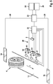
- Figure 5 shows schematically an embodiment of a device for recognizing tire markings with a camera 8 and an arrangement of light sources 61, 62, 63 which are arranged in the direction of travel F along a line on, above or in a road plane 12 of a vehicle tire 4.
- a complete test system includes at least two of the in Figure 5 arrangements shown, one for each side of the vehicle 2.
- the light sources 61, 62, 63 and the camera 8 of the arrangement are connected to a control computer 20 via electrical lines 28 or wirelessly.
- a higher-level server / computer 22 is connected to the control computer 20 as well as a display unit 24, a workstation computer 26, a system for tire pressure monitoring 14 and / or a system for vehicle identification 16.
- An energy source not shown, provides the energy required for operation.
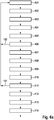
- the Figures 6a and 6b show a flowchart describing a method according to the invention for recognizing tire markings:
- a vehicle 2 approaches the measuring system and triggers a trigger signal.
- the trigger signal starts a continuous image recording with predefined control data on both sides of the vehicle (step 102).
- step 104 It is checked whether more than 50% of the tire 4 is shown in the camera image; if so, the images are stored as an image sequence for the front wheel, and the illuminance is further optimized at the same time (step 104).
- step 105 the first two images of the image sequence are analyzed, the driving speed, the position and the rolling radius of the tire 4 and the contrast ratios in the edge area of the tire 4 are determined.
- a mean value of the determined driving speed is compared with a predetermined limit value (step 106). If the mean value of the driving speed exceeds the predetermined limit value, the measurement is aborted and must be repeated (step 150).
- the light sources 61 for each front wheel 4 along the direction of travel F are activated; if necessary, further light sources 62, 63 above and / or below the road plane 12 are also activated (step 107).
- the image sequence for the front wheel 4 is ended when it has moved so far that less than 50% of it is shown in the camera image.
- the continuous image recording is continued in step 107 without changing the lighting control.
- Step 108 is followed by the continuous identification of the tire 4 of the rear wheel in the recorded images, the analysis of the contrast ratios in the edge area of the tire 4 and a corresponding optimization of the lighting.
- step 109 it is checked whether more than 50% of the tire 4 is shown in the camera image, if so, the recorded images are stored as an image sequence for the tire 4 of the rear wheel, the illuminance being continuously optimized.
- the first two images of the image sequence are analyzed, the driving speed, the position and the rolling radius of the tire 4 and the contrast ratios in the edge area of the tire 4 are determined (step 110).
- step 111 an average value of the determined driving speed is compared with a predetermined limit value. If the limit value is exceeded, the measurement is aborted and must be repeated (step 151).
- step 112 the optimal control of the light sources 61 for each rear wheel 4 along the direction of travel F, possibly also the control of further light sources 62, 63 above and / or below the road level 12 (step 112).
- the image sequence for the rear wheel is ended (step 113) when less than 50% of this is shown in the camera image.
- the image recording is stopped (step 114) and the image sequence analysis (step 200) is started separately for each tire 4.
- the image sequence analysis 200 comprises: in a first step 201 the image preprocessing for each individual image, for example using radiometric and geometric correction methods; in a second step 202 the image registration by means of model-based movement compensation, the calculation of all individual images back to the position of the reference image and the determination of the vehicle speed and the rolling radius of the tire 4; and in a third step 203 the fusion of the motion-compensated individual images to form a result image (image fusion).
- step 204 After the end of the image sequence analysis (step 204), the automatic analysis of the lettering 10 of the tires 4 in the result images takes place in step 300 for each tire 4 with the aid of known text recognition methods (OCR methods).
- OCR methods known text recognition methods
- step 400 the recognized tire lettering 19 of each tire 4 is transferred in text format to the higher-level computer / server 22 for provision in an IT system, e.g. on workstation computers in the office (e.g. in vehicle reception) or in the workshop and / or further Processing, for example the assignment to the vehicle 2 identified with a further measuring system and / or to determine target data, for example from a tire database for connected systems for tire or vehicle diagnosis.
- an IT system e.g. on workstation computers in the office (e.g. in vehicle reception) or in the workshop and / or further Processing, for example the assignment to the vehicle 2 identified with a further measuring system and / or to determine target data, for example from a tire database for connected systems for tire or vehicle diagnosis.
Landscapes
- Engineering & Computer Science (AREA)
- Theoretical Computer Science (AREA)
- Computer Vision & Pattern Recognition (AREA)
- General Physics & Mathematics (AREA)
- Physics & Mathematics (AREA)
- Multimedia (AREA)
- Artificial Intelligence (AREA)
- Data Mining & Analysis (AREA)
- Evolutionary Computation (AREA)
- Signal Processing (AREA)
- Databases & Information Systems (AREA)
- Software Systems (AREA)
- Medical Informatics (AREA)
- General Health & Medical Sciences (AREA)
- Computing Systems (AREA)
- Life Sciences & Earth Sciences (AREA)
- Bioinformatics & Cheminformatics (AREA)
- Bioinformatics & Computational Biology (AREA)
- Evolutionary Biology (AREA)
- General Engineering & Computer Science (AREA)
- Health & Medical Sciences (AREA)
- Length Measuring Devices By Optical Means (AREA)
Claims (9)
- Dispositif d'identification de l'inscription (10) sur un pneu (4)
avec :un plan de chaussée (12) ;au moins une source lumineuse orientée (61, 62, 63 ; 71, 72), réalisée de manière à éclairer le pneu (4) ;au moins une caméra (8), réalisée de manière à prendre une séquence d'images comprenant plusieurs images du flanc d'un pneu (4) roulant sur le plan de chaussée (12) ;un dispositif d'évaluation (20), réalisé de manière àdéterminer de manière algorithmique le mouvement de zones d'images locales entre deux images quelconques de la séquence d'images, sachant que différents points sur le flanc du pneu (4) évoluent le long d'une cycloïde pendant le roulement, et ainsi à obtenir pour chaque zone d'image des paramètres du mouvement cycloïde correspondant ; età l'aide des paramètres ainsi déterminés, ramener les images de la séquence d'images à une image centrale prise au hasard et, en fusionnant les images ainsi compensées en mouvement, synthétiser une image finale du flanc du pneu (4), dans laquelle toutes les arêtes de l'inscription sont représentées de manière bien contrastée, et évaluer l'image finale synthétisée au moyen d'un procédé de reconnaissance de caractères. - Dispositif selon la revendication 1, dans lequel plusieurs sources lumineuses (61) sont disposées en ligne dans la direction de roulement du pneu (4).
- Dispositif selon la revendication 1 ou 2, dans lequel plusieurs sources lumineuses (62) sont prévues à différentes distances verticales du plan de chaussée (12).
- Dispositif selon l'une quelconque des revendications 1 à 3, dans lequel plusieurs sources lumineuses (63) sont réalisées à différentes positions transversalement à la direction de roulement du pneu (4).
- Dispositif selon l'une quelconque des revendications 1 à 4, dans lequel au moins l'une des sources lumineuses (61, 62, 63) présente des éléments d'éclairage pouvant être commandés séparément (61a, 61b, 62a, 62b).
- Dispositif selon l'une quelconque des revendications 1 à 5, dans lequel plusieurs sources lumineuses (61, 62, 63) sont réalisées de manière à éclairer le pneu (4) avec une lumière de différentes longueurs d'onde.
- Dispositif selon l'une quelconque des revendications 1 à 6, dans lequel au moins l'une des sources lumineuses (61, 62, 63) peut être utilisée en mode flash.
- Dispositif selon l'une quelconque des revendications 1 à 7 avec un agencement de miroirs (71, 72), réalisé de manière à diriger la lumière naturelle du soleil et/ou la lumière d'au moins un phare (70) du véhicule (2) sur le flanc d'au moins un pneu (4).
- Procédé d'identification de l'inscription (10) sur le flanc d'un pneu (4), ce procédé comprenant l'éclairage du pneu (4) avec au moins une source lumineuse orientée (61, 62, 63 ; 71, 72) ; ce procédé incluant en outre les étapes suivantes :passage du pneu (4) devant au moins une caméra (8) ;prise d'une séquence d'images composée de plusieurs images du flanc du pneu (4) passant devant la caméra (8), une au moins ;détermination algorithmique du mouvement de zones d'images locales entre deux images quelconques de la séquence d'images, sachant que différents points sur le flanc du pneu (4) évoluent le long d'une cycloïde pendant le roulement, afin d'obtenir pour chaque zone d'image des paramètres du mouvement cycloïde correspondant ;ramener les images de la séquence d'images à une image centrale prise au hasard avec l'aide des paramètres ainsi déterminés ;en fusionnant les images ainsi compensées en mouvement, synthétisation d'une image finale du flanc du pneu (4), dans laquelle toutes les arêtes de l'inscription sont représentées de manière bien contrastée ; etévaluation de l'image centrale synthétisée au moyen d'un procédé de reconnaissance de caractères.
Applications Claiming Priority (2)
| Application Number | Priority Date | Filing Date | Title |
|---|---|---|---|
| DE201310207374 DE102013207374A1 (de) | 2013-04-23 | 2013-04-23 | Vorrichtung und Verfahren zum Erkennen von Beschriftungen auf Fahrzeugreifen |
| PCT/EP2014/053809 WO2014173564A1 (fr) | 2013-04-23 | 2014-02-27 | Dispositif et procédé d'identification d'inscriptions sur des pneus de véhicules |
Publications (2)
| Publication Number | Publication Date |
|---|---|
| EP2989594A1 EP2989594A1 (fr) | 2016-03-02 |
| EP2989594B1 true EP2989594B1 (fr) | 2021-04-07 |
Family
ID=50231138
Family Applications (1)
| Application Number | Title | Priority Date | Filing Date |
|---|---|---|---|
| EP14707984.2A Active EP2989594B1 (fr) | 2013-04-23 | 2014-02-27 | Dispositif et procédé d'identification d'inscriptions sur des pneus de véhicules |
Country Status (5)
| Country | Link |
|---|---|
| US (1) | US10313574B2 (fr) |
| EP (1) | EP2989594B1 (fr) |
| CN (1) | CN105164697B (fr) |
| DE (1) | DE102013207374A1 (fr) |
| WO (1) | WO2014173564A1 (fr) |
Families Citing this family (17)
| Publication number | Priority date | Publication date | Assignee | Title |
|---|---|---|---|---|
| EP3237837B1 (fr) * | 2014-12-22 | 2020-02-19 | Pirelli Tyre S.p.A. | Procédé et appareil pour contrôler des pneus dans une chaîne de production |
| KR102534392B1 (ko) | 2014-12-22 | 2023-05-19 | 피렐리 타이어 소시에떼 퍼 아찌오니 | 생산라인에서 타이어를 제어하기 위한 기기 |
| GB201517926D0 (en) * | 2015-10-09 | 2015-11-25 | Wheelright Ltd | Tyre condition analysis |
| US10475201B1 (en) * | 2016-02-02 | 2019-11-12 | Hunter Engineering Company | Method and apparatus for determining wheel rim and tire dimensions on a moving vehicle |
| ITUA20162722A1 (it) * | 2016-04-19 | 2017-10-19 | Butler Eng And Marketing S P A | Dispositivo e metodo per l'analisi e il rilevamento di caratteristiche geometriche di un oggetto |
| US10078892B1 (en) * | 2017-03-16 | 2018-09-18 | GM Global Technology Operations LLC | Methods and systems for vehicle tire analysis using vehicle mounted cameras |
| IT201700039288A1 (it) | 2017-04-10 | 2018-10-10 | Nexion Spa | Metodo e apparato di controllo di pneumatici delle ruote di un veicolo |
| WO2019084385A1 (fr) * | 2017-10-26 | 2019-05-02 | Tire Profiles, Llc | Lecteur de code de pneu |
| WO2020205640A1 (fr) * | 2019-04-01 | 2020-10-08 | Exxonmobil Chemical Patents Inc. | Système pour identifier des véhicules et détecter des caractéristiques de pneu |
| US11614380B2 (en) | 2019-07-02 | 2023-03-28 | Hunter Engineering Company | System and method for acquisition of tire sidewall data from a moving vehicle |
| CN111914817B (zh) * | 2020-09-21 | 2024-04-02 | 南京航空航天大学 | 一种基于种子点的道路识别方法及系统 |
| US12188845B1 (en) * | 2020-12-17 | 2025-01-07 | Hunter Engineering Company | System and method for capturing tire sidewall data from a moving vehicle |
| CN114155533A (zh) * | 2021-12-02 | 2022-03-08 | 苏州惟信易量智能科技有限公司 | 一种基于点云数据的字符分割方法和系统 |
| WO2023097600A1 (fr) * | 2021-12-02 | 2023-06-08 | 苏州惟信易量智能科技有限公司 | Procédé et système de reconnaissance de caractères tridimensionnels |
| CN114332838A (zh) * | 2021-12-28 | 2022-04-12 | 深圳市二郎神视觉科技有限公司 | 一种轮胎视觉检测方法、装置及计算机可读存储介质 |
| CN116878629B (zh) * | 2023-07-21 | 2026-04-21 | 东南大学 | 基于计算机视觉的侧立式收费站车辆动态称重方法 |
| SE2450755A1 (en) | 2024-07-03 | 2025-11-18 | Wheelscanning Sweden AB | Vehicle inspection system and method for inspecting a sidewall of a tire in such a system |
Family Cites Families (28)
| Publication number | Priority date | Publication date | Assignee | Title |
|---|---|---|---|---|
| JPS62184908A (ja) * | 1986-02-07 | 1987-08-13 | Bridgestone Corp | タイヤの自動判別方法 |
| NL8600849A (nl) | 1986-04-03 | 1987-11-02 | Philips Nv | Inrichting voor het optisch identificeren van voorwerpen. |
| US4745469A (en) * | 1987-02-18 | 1988-05-17 | Perceptron, Inc. | Vehicle wheel alignment apparatus and method |
| US5687249A (en) * | 1993-09-06 | 1997-11-11 | Nippon Telephone And Telegraph | Method and apparatus for extracting features of moving objects |
| GB9418091D0 (en) | 1994-09-08 | 1994-10-26 | Russell Malcom B | Tyre surface scanner |
| GB9516968D0 (en) | 1995-08-18 | 1995-10-18 | Mot Technologies Ltd | Automated system for vehicle condition evaluation |
| EP0816799A3 (fr) | 1996-07-04 | 1998-01-28 | Sun Electric UK Ltd. | Mesure de la condition d'un pneumatique |
| US6237234B1 (en) * | 1999-09-28 | 2001-05-29 | Snap-On Technologies, Inc. | Method and apparatus for measuring vehicle wheel roll radius |
| US6681195B1 (en) * | 2000-03-22 | 2004-01-20 | Laser Technology, Inc. | Compact speed measurement system with onsite digital image capture, processing, and portable display |
| DE10062254C2 (de) | 2000-12-14 | 2002-12-19 | Fraunhofer Ges Forschung | Verfahren und Vorrichtung zum Charakterisieren einer Oberfläche und Verfahren und Vorrichtung zur Ermittlung einer Formanomalie einer Oberfläche |
| US6735337B2 (en) | 2001-02-02 | 2004-05-11 | Shih-Jong J. Lee | Robust method for automatic reading of skewed, rotated or partially obscured characters |
| DE10143522C2 (de) | 2001-09-05 | 2003-07-10 | Fraunhofer Ges Forschung | Verfahren und Vorrichtung zum Untersuchen eines Objekts |
| JP3787294B2 (ja) | 2001-10-12 | 2006-06-21 | 株式会社マイクロビジョン | 積雪用タイヤ検出装置 |
| JP4679073B2 (ja) * | 2004-05-18 | 2011-04-27 | 株式会社ブリヂストン | タイヤ凹凸図形の検査方法、および、タイヤ凹凸図形検査装置 |
| US7295948B2 (en) | 2005-01-15 | 2007-11-13 | Jetter Heinz L | Laser system for marking tires |
| GB2425385B (en) * | 2005-04-18 | 2007-08-01 | Pips Technology Ltd | Vehicle speed monitoring system |
| JP4887373B2 (ja) * | 2005-11-22 | 2012-02-29 | シェーファー・フランク・ハー | タイヤの形状深さおよび形状の種類ならびに走行時の車両の速度および地上高の検出装置 |
| CA2674830A1 (fr) * | 2007-01-05 | 2008-07-17 | Nestor, Inc. | Systeme de detection de vitesse video |
| US8087301B2 (en) * | 2007-09-24 | 2012-01-03 | Infineon Technologies Ag | Optical systems and methods for determining tire characteristics |
| JP5090126B2 (ja) * | 2007-10-23 | 2012-12-05 | アルパイン株式会社 | 車載用撮像装置 |
| EP2071795B1 (fr) | 2007-12-12 | 2010-03-24 | Lg Electronics Inc. | Appareil pour la transmission et la réception d'un signal et procédé pour la transmission et la réception d'un signal |
| ATE545917T1 (de) * | 2007-12-19 | 2012-03-15 | Michelin Soc Tech | Verfahren zur verarbeitung eines dreidimensionalen bildes einer reifenfläche für seine verwendung zur überprüfung dieser fläche |
| DE102008023936A1 (de) | 2008-02-10 | 2009-08-27 | Vmt Vision Machine Technic Bildverarbeitungssysteme Gmbh | Verfahren und Vorrichtung zum Lesen einer Profilschrift auf wenigstens einer der Seitenflächen eines Reifens |
| JP4480773B2 (ja) * | 2008-04-01 | 2010-06-16 | トヨタ自動車株式会社 | タイヤ種別判別方法、並びにこれを用いた車両検査方法及び装置 |
| GB2472793B (en) * | 2009-08-17 | 2012-05-09 | Pips Technology Ltd | A method and system for measuring the speed of a vehicle |
| JP5371848B2 (ja) * | 2009-12-07 | 2013-12-18 | 株式会社神戸製鋼所 | タイヤ形状検査方法、及びタイヤ形状検査装置 |
| CN102248870A (zh) * | 2010-05-19 | 2011-11-23 | 上海红硕阳化工有限公司 | 一种容易识别的轮胎标识方法 |
| US20130021471A1 (en) * | 2011-07-21 | 2013-01-24 | Google Inc. | Reflective Surface Orientating with Multiple View Ports |
-
2013
- 2013-04-23 DE DE201310207374 patent/DE102013207374A1/de not_active Withdrawn
-
2014
- 2014-02-27 CN CN201480022823.2A patent/CN105164697B/zh not_active Expired - Fee Related
- 2014-02-27 WO PCT/EP2014/053809 patent/WO2014173564A1/fr not_active Ceased
- 2014-02-27 US US14/784,160 patent/US10313574B2/en active Active
- 2014-02-27 EP EP14707984.2A patent/EP2989594B1/fr active Active
Non-Patent Citations (1)
| Title |
|---|
| None * |
Also Published As
| Publication number | Publication date |
|---|---|
| US10313574B2 (en) | 2019-06-04 |
| DE102013207374A1 (de) | 2014-10-23 |
| EP2989594A1 (fr) | 2016-03-02 |
| CN105164697A (zh) | 2015-12-16 |
| US20160127625A1 (en) | 2016-05-05 |
| WO2014173564A1 (fr) | 2014-10-30 |
| CN105164697B (zh) | 2019-05-31 |
Similar Documents
| Publication | Publication Date | Title |
|---|---|---|
| EP2989594B1 (fr) | Dispositif et procédé d'identification d'inscriptions sur des pneus de véhicules | |
| EP2732236B1 (fr) | Dispositif et procédé optiques de contrôle de pneumatiques | |
| EP2047211B1 (fr) | Procédé de détermination de la géométrie axiale d'un véhicule | |
| EP3479058B1 (fr) | Procédé et dispositif servant à mesurer des dommages subis par une carrosserie | |
| EP3183721B1 (fr) | Procédé et dispositif de comptage sans contact d'essieux d'un véhicule et système de comptage d'essieux pour trafic routier | |
| EP2329222B1 (fr) | Procédé et dispositif de mesure pour déterminer la géométrie de roues ou d'essieux d'un véhicule | |
| EP3696537B1 (fr) | Dispositif et procédé de détection des dommages sur un véhicule en déplacement | |
| EP3830517B1 (fr) | Procédé et dispositif de reconnaissance et d'analyse de défauts de surface d'objets tridimensionnels présentant une surface réfléchissante, en particulier de carrosseries de véhicule automobile | |
| EP1875164B1 (fr) | Procede de determination de la geometrie des roues et/ou des essieux de vehicules a moteur | |
| EP2936049A1 (fr) | Dispositif et procédé de mesure de la profondeur des sculptures d'un pneu | |
| DE112017007347T5 (de) | Objekterkennungsvorrichtung und fahrzeug | |
| DE102005063083A1 (de) | Verfahren zur optischen Fahrwerksvermessung | |
| EP4198894A1 (fr) | Détection de contour de véhicule basée sur une caméra pour des installations de traitement de véhicules | |
| DE102015223500B4 (de) | Verfahren und Vorrichtung zur Prüfung der Funktionalität einer außenseitigen Lichteinrichtung eines Fahrzeugs | |
| EP3049757B1 (fr) | Mesure de châssis en présence de lumière ambiante | |
| EP3407010A1 (fr) | Dispositif et procédé pour mesurer la profondeur du profil d'un pneu | |
| DE102022002766B4 (de) | Verfahren zur dreidimensionalen Rekonstruktion einer Fahrzeugumgebung | |
| WO2024032971A1 (fr) | Dispositif et procédé de mesure d'images virtuelles tridimensionnelles et d'objets sur un affichage tête haute | |
| EP4372349B1 (fr) | Dispositif et procédé d'alignement d'un appareil de contrôle de position de phare | |
| DE102017208810A1 (de) | Vorrichtung und Verfahren zur Messung der Profiltiefe eines Reifens | |
| EP2103984B1 (fr) | Procédé et dispositif de traitement de données d'image | |
| DE102021202584A1 (de) | Verfahren und Vorrichtung zum Erzeugen eines Lichtobjekts | |
| DE102006048726A1 (de) | Verfahren zum Vermessen der Rad- oder Achsgeometrie eines Fahrzeugs | |
| DE102023135119A1 (de) | Verfahren zum Umwandeln eines Anfangsdatensatzes wenigstens eines Punktes einer Anfangspunktwolke in einen neuen Datensatz einer neuen Punktwolke durch spiegeln wenigstens einer Richtungskoordinate, Mittel zum Durchführen wenigstens eines Teils des Verfahrens, Detektionsvorrichtung, Fahrerassistenzsystem und Fahrzeug | |
| DE102022212480A1 (de) | Matrixlichtlenkung zur Objekterkennung für automatisiertes Fahren |
Legal Events
| Date | Code | Title | Description |
|---|---|---|---|
| PUAI | Public reference made under article 153(3) epc to a published international application that has entered the european phase |
Free format text: ORIGINAL CODE: 0009012 |
|
| 17P | Request for examination filed |
Effective date: 20151123 |
|
| AK | Designated contracting states |
Kind code of ref document: A1 Designated state(s): AL AT BE BG CH CY CZ DE DK EE ES FI FR GB GR HR HU IE IS IT LI LT LU LV MC MK MT NL NO PL PT RO RS SE SI SK SM TR |
|
| AX | Request for extension of the european patent |
Extension state: BA ME |
|
| DAX | Request for extension of the european patent (deleted) | ||
| STAA | Information on the status of an ep patent application or granted ep patent |
Free format text: STATUS: EXAMINATION IS IN PROGRESS |
|
| 17Q | First examination report despatched |
Effective date: 20181031 |
|
| RAP1 | Party data changed (applicant data changed or rights of an application transferred) |
Owner name: BEISSBARTH GMBH |
|
| RIC1 | Information provided on ipc code assigned before grant |
Ipc: G06K 9/20 20060101ALI20190930BHEP Ipc: G06K 9/32 20060101AFI20190930BHEP Ipc: G06K 9/62 20060101ALI20190930BHEP |
|
| REG | Reference to a national code |
Ref country code: DE Ref legal event code: R079 Ref document number: 502014015462 Country of ref document: DE Free format text: PREVIOUS MAIN CLASS: G06K0009200000 Ipc: G06K0009320000 |
|
| GRAP | Despatch of communication of intention to grant a patent |
Free format text: ORIGINAL CODE: EPIDOSNIGR1 |
|
| STAA | Information on the status of an ep patent application or granted ep patent |
Free format text: STATUS: GRANT OF PATENT IS INTENDED |
|
| RIC1 | Information provided on ipc code assigned before grant |
Ipc: G06K 9/62 20060101ALI20201110BHEP Ipc: G06K 9/20 20060101ALI20201110BHEP Ipc: G06K 9/32 20060101AFI20201110BHEP Ipc: G06T 7/73 20170101ALI20201110BHEP |
|
| INTG | Intention to grant announced |
Effective date: 20201126 |
|
| GRAS | Grant fee paid |
Free format text: ORIGINAL CODE: EPIDOSNIGR3 |
|
| GRAA | (expected) grant |
Free format text: ORIGINAL CODE: 0009210 |
|
| STAA | Information on the status of an ep patent application or granted ep patent |
Free format text: STATUS: THE PATENT HAS BEEN GRANTED |
|
| AK | Designated contracting states |
Kind code of ref document: B1 Designated state(s): AL AT BE BG CH CY CZ DE DK EE ES FI FR GB GR HR HU IE IS IT LI LT LU LV MC MK MT NL NO PL PT RO RS SE SI SK SM TR |
|
| REG | Reference to a national code |
Ref country code: GB Ref legal event code: FG4D Free format text: NOT ENGLISH |
|
| REG | Reference to a national code |
Ref country code: AT Ref legal event code: REF Ref document number: 1380656 Country of ref document: AT Kind code of ref document: T Effective date: 20210415 Ref country code: CH Ref legal event code: EP |
|
| REG | Reference to a national code |
Ref country code: DE Ref legal event code: R096 Ref document number: 502014015462 Country of ref document: DE |
|
| REG | Reference to a national code |
Ref country code: IE Ref legal event code: FG4D Free format text: LANGUAGE OF EP DOCUMENT: GERMAN |
|
| REG | Reference to a national code |
Ref country code: LT Ref legal event code: MG9D |
|
| REG | Reference to a national code |
Ref country code: NL Ref legal event code: MP Effective date: 20210407 |
|
| PG25 | Lapsed in a contracting state [announced via postgrant information from national office to epo] |
Ref country code: HR Free format text: LAPSE BECAUSE OF FAILURE TO SUBMIT A TRANSLATION OF THE DESCRIPTION OR TO PAY THE FEE WITHIN THE PRESCRIBED TIME-LIMIT Effective date: 20210407 Ref country code: BG Free format text: LAPSE BECAUSE OF FAILURE TO SUBMIT A TRANSLATION OF THE DESCRIPTION OR TO PAY THE FEE WITHIN THE PRESCRIBED TIME-LIMIT Effective date: 20210707 Ref country code: FI Free format text: LAPSE BECAUSE OF FAILURE TO SUBMIT A TRANSLATION OF THE DESCRIPTION OR TO PAY THE FEE WITHIN THE PRESCRIBED TIME-LIMIT Effective date: 20210407 Ref country code: NL Free format text: LAPSE BECAUSE OF FAILURE TO SUBMIT A TRANSLATION OF THE DESCRIPTION OR TO PAY THE FEE WITHIN THE PRESCRIBED TIME-LIMIT Effective date: 20210407 Ref country code: LT Free format text: LAPSE BECAUSE OF FAILURE TO SUBMIT A TRANSLATION OF THE DESCRIPTION OR TO PAY THE FEE WITHIN THE PRESCRIBED TIME-LIMIT Effective date: 20210407 |
|
| REG | Reference to a national code |
Ref country code: DE Ref legal event code: R079 Ref document number: 502014015462 Country of ref document: DE Free format text: PREVIOUS MAIN CLASS: G06K0009320000 Ipc: G06V0030146000 |
|
| PG25 | Lapsed in a contracting state [announced via postgrant information from national office to epo] |
Ref country code: LV Free format text: LAPSE BECAUSE OF FAILURE TO SUBMIT A TRANSLATION OF THE DESCRIPTION OR TO PAY THE FEE WITHIN THE PRESCRIBED TIME-LIMIT Effective date: 20210407 Ref country code: GR Free format text: LAPSE BECAUSE OF FAILURE TO SUBMIT A TRANSLATION OF THE DESCRIPTION OR TO PAY THE FEE WITHIN THE PRESCRIBED TIME-LIMIT Effective date: 20210708 Ref country code: IS Free format text: LAPSE BECAUSE OF FAILURE TO SUBMIT A TRANSLATION OF THE DESCRIPTION OR TO PAY THE FEE WITHIN THE PRESCRIBED TIME-LIMIT Effective date: 20210807 Ref country code: ES Free format text: LAPSE BECAUSE OF FAILURE TO SUBMIT A TRANSLATION OF THE DESCRIPTION OR TO PAY THE FEE WITHIN THE PRESCRIBED TIME-LIMIT Effective date: 20210407 Ref country code: PT Free format text: LAPSE BECAUSE OF FAILURE TO SUBMIT A TRANSLATION OF THE DESCRIPTION OR TO PAY THE FEE WITHIN THE PRESCRIBED TIME-LIMIT Effective date: 20210809 Ref country code: NO Free format text: LAPSE BECAUSE OF FAILURE TO SUBMIT A TRANSLATION OF THE DESCRIPTION OR TO PAY THE FEE WITHIN THE PRESCRIBED TIME-LIMIT Effective date: 20210707 Ref country code: PL Free format text: LAPSE BECAUSE OF FAILURE TO SUBMIT A TRANSLATION OF THE DESCRIPTION OR TO PAY THE FEE WITHIN THE PRESCRIBED TIME-LIMIT Effective date: 20210407 Ref country code: SE Free format text: LAPSE BECAUSE OF FAILURE TO SUBMIT A TRANSLATION OF THE DESCRIPTION OR TO PAY THE FEE WITHIN THE PRESCRIBED TIME-LIMIT Effective date: 20210407 Ref country code: RS Free format text: LAPSE BECAUSE OF FAILURE TO SUBMIT A TRANSLATION OF THE DESCRIPTION OR TO PAY THE FEE WITHIN THE PRESCRIBED TIME-LIMIT Effective date: 20210407 |
|
| REG | Reference to a national code |
Ref country code: DE Ref legal event code: R097 Ref document number: 502014015462 Country of ref document: DE |
|
| PG25 | Lapsed in a contracting state [announced via postgrant information from national office to epo] |
Ref country code: RO Free format text: LAPSE BECAUSE OF FAILURE TO SUBMIT A TRANSLATION OF THE DESCRIPTION OR TO PAY THE FEE WITHIN THE PRESCRIBED TIME-LIMIT Effective date: 20210407 Ref country code: EE Free format text: LAPSE BECAUSE OF FAILURE TO SUBMIT A TRANSLATION OF THE DESCRIPTION OR TO PAY THE FEE WITHIN THE PRESCRIBED TIME-LIMIT Effective date: 20210407 Ref country code: CZ Free format text: LAPSE BECAUSE OF FAILURE TO SUBMIT A TRANSLATION OF THE DESCRIPTION OR TO PAY THE FEE WITHIN THE PRESCRIBED TIME-LIMIT Effective date: 20210407 Ref country code: DK Free format text: LAPSE BECAUSE OF FAILURE TO SUBMIT A TRANSLATION OF THE DESCRIPTION OR TO PAY THE FEE WITHIN THE PRESCRIBED TIME-LIMIT Effective date: 20210407 Ref country code: SM Free format text: LAPSE BECAUSE OF FAILURE TO SUBMIT A TRANSLATION OF THE DESCRIPTION OR TO PAY THE FEE WITHIN THE PRESCRIBED TIME-LIMIT Effective date: 20210407 Ref country code: SK Free format text: LAPSE BECAUSE OF FAILURE TO SUBMIT A TRANSLATION OF THE DESCRIPTION OR TO PAY THE FEE WITHIN THE PRESCRIBED TIME-LIMIT Effective date: 20210407 |
|
| PLBE | No opposition filed within time limit |
Free format text: ORIGINAL CODE: 0009261 |
|
| STAA | Information on the status of an ep patent application or granted ep patent |
Free format text: STATUS: NO OPPOSITION FILED WITHIN TIME LIMIT |
|
| 26N | No opposition filed |
Effective date: 20220110 |
|
| PG25 | Lapsed in a contracting state [announced via postgrant information from national office to epo] |
Ref country code: IS Free format text: LAPSE BECAUSE OF FAILURE TO SUBMIT A TRANSLATION OF THE DESCRIPTION OR TO PAY THE FEE WITHIN THE PRESCRIBED TIME-LIMIT Effective date: 20210807 Ref country code: AL Free format text: LAPSE BECAUSE OF FAILURE TO SUBMIT A TRANSLATION OF THE DESCRIPTION OR TO PAY THE FEE WITHIN THE PRESCRIBED TIME-LIMIT Effective date: 20210407 |
|
| PG25 | Lapsed in a contracting state [announced via postgrant information from national office to epo] |
Ref country code: MC Free format text: LAPSE BECAUSE OF FAILURE TO SUBMIT A TRANSLATION OF THE DESCRIPTION OR TO PAY THE FEE WITHIN THE PRESCRIBED TIME-LIMIT Effective date: 20210407 |
|
| REG | Reference to a national code |
Ref country code: CH Ref legal event code: PL |
|
| REG | Reference to a national code |
Ref country code: BE Ref legal event code: MM Effective date: 20220228 |
|
| PG25 | Lapsed in a contracting state [announced via postgrant information from national office to epo] |
Ref country code: LU Free format text: LAPSE BECAUSE OF NON-PAYMENT OF DUE FEES Effective date: 20220227 |
|
| PG25 | Lapsed in a contracting state [announced via postgrant information from national office to epo] |
Ref country code: LI Free format text: LAPSE BECAUSE OF NON-PAYMENT OF DUE FEES Effective date: 20220228 Ref country code: IE Free format text: LAPSE BECAUSE OF NON-PAYMENT OF DUE FEES Effective date: 20220227 Ref country code: CH Free format text: LAPSE BECAUSE OF NON-PAYMENT OF DUE FEES Effective date: 20220228 |
|
| PG25 | Lapsed in a contracting state [announced via postgrant information from national office to epo] |
Ref country code: BE Free format text: LAPSE BECAUSE OF NON-PAYMENT OF DUE FEES Effective date: 20220228 |
|
| REG | Reference to a national code |
Ref country code: AT Ref legal event code: MM01 Ref document number: 1380656 Country of ref document: AT Kind code of ref document: T Effective date: 20220227 |
|
| PG25 | Lapsed in a contracting state [announced via postgrant information from national office to epo] |
Ref country code: AT Free format text: LAPSE BECAUSE OF NON-PAYMENT OF DUE FEES Effective date: 20220227 |
|
| PGFP | Annual fee paid to national office [announced via postgrant information from national office to epo] |
Ref country code: GB Payment date: 20230323 Year of fee payment: 10 |
|
| REG | Reference to a national code |
Ref country code: DE Ref legal event code: R081 Ref document number: 502014015462 Country of ref document: DE Owner name: BEISSBARTH AUTOMOTIVE TESTING SOLUTIONS GMBH, DE Free format text: FORMER OWNER: BEISSBARTH GMBH, 80993 MUENCHEN, DE |
|
| P01 | Opt-out of the competence of the unified patent court (upc) registered |
Effective date: 20230707 |
|
| REG | Reference to a national code |
Ref country code: GB Ref legal event code: 732E Free format text: REGISTERED BETWEEN 20230907 AND 20230913 |
|
| PG25 | Lapsed in a contracting state [announced via postgrant information from national office to epo] |
Ref country code: HU Free format text: LAPSE BECAUSE OF FAILURE TO SUBMIT A TRANSLATION OF THE DESCRIPTION OR TO PAY THE FEE WITHIN THE PRESCRIBED TIME-LIMIT; INVALID AB INITIO Effective date: 20140227 |
|
| PG25 | Lapsed in a contracting state [announced via postgrant information from national office to epo] |
Ref country code: MK Free format text: LAPSE BECAUSE OF FAILURE TO SUBMIT A TRANSLATION OF THE DESCRIPTION OR TO PAY THE FEE WITHIN THE PRESCRIBED TIME-LIMIT Effective date: 20210407 Ref country code: CY Free format text: LAPSE BECAUSE OF FAILURE TO SUBMIT A TRANSLATION OF THE DESCRIPTION OR TO PAY THE FEE WITHIN THE PRESCRIBED TIME-LIMIT Effective date: 20210407 |
|
| PGFP | Annual fee paid to national office [announced via postgrant information from national office to epo] |
Ref country code: IT Payment date: 20240222 Year of fee payment: 11 Ref country code: FR Payment date: 20240220 Year of fee payment: 11 |
|
| PGFP | Annual fee paid to national office [announced via postgrant information from national office to epo] |
Ref country code: DE Payment date: 20240424 Year of fee payment: 11 |
|
| PG25 | Lapsed in a contracting state [announced via postgrant information from national office to epo] |
Ref country code: MT Free format text: LAPSE BECAUSE OF FAILURE TO SUBMIT A TRANSLATION OF THE DESCRIPTION OR TO PAY THE FEE WITHIN THE PRESCRIBED TIME-LIMIT Effective date: 20210407 |
|
| GBPC | Gb: european patent ceased through non-payment of renewal fee |
Effective date: 20240227 |
|
| PG25 | Lapsed in a contracting state [announced via postgrant information from national office to epo] |
Ref country code: GB Free format text: LAPSE BECAUSE OF NON-PAYMENT OF DUE FEES Effective date: 20240227 |
|
| PG25 | Lapsed in a contracting state [announced via postgrant information from national office to epo] |
Ref country code: GB Free format text: LAPSE BECAUSE OF NON-PAYMENT OF DUE FEES Effective date: 20240227 |
|
| REG | Reference to a national code |
Ref country code: DE Ref legal event code: R119 Ref document number: 502014015462 Country of ref document: DE |
|
| PG25 | Lapsed in a contracting state [announced via postgrant information from national office to epo] |
Ref country code: TR Free format text: LAPSE BECAUSE OF FAILURE TO SUBMIT A TRANSLATION OF THE DESCRIPTION OR TO PAY THE FEE WITHIN THE PRESCRIBED TIME-LIMIT Effective date: 20210407 |
|
| PG25 | Lapsed in a contracting state [announced via postgrant information from national office to epo] |
Ref country code: DE Free format text: LAPSE BECAUSE OF NON-PAYMENT OF DUE FEES Effective date: 20250902 |
|
| PG25 | Lapsed in a contracting state [announced via postgrant information from national office to epo] |
Ref country code: IT Free format text: LAPSE BECAUSE OF NON-PAYMENT OF DUE FEES Effective date: 20250227 Ref country code: FR Free format text: LAPSE BECAUSE OF NON-PAYMENT OF DUE FEES Effective date: 20250228 |