EP3830963B1 - Sende-/empfangssystem für funksignale mit integrierter sendeverstärker-schutzfunktion - Google Patents
Sende-/empfangssystem für funksignale mit integrierter sendeverstärker-schutzfunktion Download PDFInfo
- Publication number
- EP3830963B1 EP3830963B1 EP19742343.7A EP19742343A EP3830963B1 EP 3830963 B1 EP3830963 B1 EP 3830963B1 EP 19742343 A EP19742343 A EP 19742343A EP 3830963 B1 EP3830963 B1 EP 3830963B1
- Authority
- EP
- European Patent Office
- Prior art keywords
- amplifier module
- antenna
- transmit
- receive
- high frequency
- Prior art date
- Legal status (The legal status is an assumption and is not a legal conclusion. Google has not performed a legal analysis and makes no representation as to the accuracy of the status listed.)
- Active
Links
Images

Classifications
-
- H—ELECTRICITY
- H04—ELECTRIC COMMUNICATION TECHNIQUE
- H04B—TRANSMISSION
- H04B1/00—Details of transmission systems, not covered by a single one of groups H04B3/00 - H04B13/00; Details of transmission systems not characterised by the medium used for transmission
- H04B1/02—Transmitters
- H04B1/04—Circuits
- H04B1/0458—Arrangements for matching and coupling between power amplifier and antenna or between amplifying stages
-
- H—ELECTRICITY
- H03—ELECTRONIC CIRCUITRY
- H03F—AMPLIFIERS
- H03F1/00—Details of amplifiers with only discharge tubes, only semiconductor devices or only unspecified devices as amplifying elements
- H03F1/52—Circuit arrangements for protecting such amplifiers
-
- H—ELECTRICITY
- H03—ELECTRONIC CIRCUITRY
- H03F—AMPLIFIERS
- H03F3/00—Amplifiers with only discharge tubes or only semiconductor devices as amplifying elements
- H03F3/189—High-frequency amplifiers, e.g. radio frequency amplifiers
-
- H—ELECTRICITY
- H03—ELECTRONIC CIRCUITRY
- H03F—AMPLIFIERS
- H03F3/00—Amplifiers with only discharge tubes or only semiconductor devices as amplifying elements
- H03F3/20—Power amplifiers, e.g. Class B amplifiers, Class C amplifiers
- H03F3/24—Power amplifiers, e.g. Class B amplifiers, Class C amplifiers of transmitter output stages
-
- H—ELECTRICITY
- H04—ELECTRIC COMMUNICATION TECHNIQUE
- H04B—TRANSMISSION
- H04B1/00—Details of transmission systems, not covered by a single one of groups H04B3/00 - H04B13/00; Details of transmission systems not characterised by the medium used for transmission
- H04B1/38—Transceivers, i.e. devices in which transmitter and receiver form a structural unit and in which at least one part is used for functions of transmitting and receiving
- H04B1/3822—Transceivers, i.e. devices in which transmitter and receiver form a structural unit and in which at least one part is used for functions of transmitting and receiving specially adapted for use in vehicles
-
- H—ELECTRICITY
- H04—ELECTRIC COMMUNICATION TECHNIQUE
- H04B—TRANSMISSION
- H04B1/00—Details of transmission systems, not covered by a single one of groups H04B3/00 - H04B13/00; Details of transmission systems not characterised by the medium used for transmission
- H04B1/74—Details of transmission systems, not covered by a single one of groups H04B3/00 - H04B13/00; Details of transmission systems not characterised by the medium used for transmission for increasing reliability, e.g. using redundant or spare channels or apparatus
- H04B1/745—Details of transmission systems, not covered by a single one of groups H04B3/00 - H04B13/00; Details of transmission systems not characterised by the medium used for transmission for increasing reliability, e.g. using redundant or spare channels or apparatus using by-passing or self-healing methods
-
- H—ELECTRICITY
- H03—ELECTRONIC CIRCUITRY
- H03F—AMPLIFIERS
- H03F2200/00—Indexing scheme relating to amplifiers
- H03F2200/451—Indexing scheme relating to amplifiers the amplifier being a radio frequency amplifier
-
- H—ELECTRICITY
- H04—ELECTRIC COMMUNICATION TECHNIQUE
- H04B—TRANSMISSION
- H04B1/00—Details of transmission systems, not covered by a single one of groups H04B3/00 - H04B13/00; Details of transmission systems not characterised by the medium used for transmission
- H04B1/02—Transmitters
- H04B1/04—Circuits
- H04B1/0466—Fault detection or indication
-
- H—ELECTRICITY
- H04—ELECTRIC COMMUNICATION TECHNIQUE
- H04B—TRANSMISSION
- H04B1/00—Details of transmission systems, not covered by a single one of groups H04B3/00 - H04B13/00; Details of transmission systems not characterised by the medium used for transmission
- H04B1/06—Receivers
- H04B1/16—Circuits
- H04B1/18—Input circuits, e.g. for coupling to an antenna or a transmission line
-
- H—ELECTRICITY
- H04—ELECTRIC COMMUNICATION TECHNIQUE
- H04B—TRANSMISSION
- H04B1/00—Details of transmission systems, not covered by a single one of groups H04B3/00 - H04B13/00; Details of transmission systems not characterised by the medium used for transmission
- H04B1/38—Transceivers, i.e. devices in which transmitter and receiver form a structural unit and in which at least one part is used for functions of transmitting and receiving
- H04B1/40—Circuits
- H04B1/44—Transmit/receive switching
- H04B1/48—Transmit/receive switching in circuits for connecting transmitter and receiver to a common transmission path, e.g. by energy of transmitter
-
- H—ELECTRICITY
- H04—ELECTRIC COMMUNICATION TECHNIQUE
- H04B—TRANSMISSION
- H04B17/00—Monitoring; Testing
- H04B17/10—Monitoring; Testing of transmitters
- H04B17/101—Monitoring; Testing of transmitters for measurement of specific parameters of the transmitter or components thereof
- H04B17/103—Reflected power, e.g. return loss
-
- H—ELECTRICITY
- H04—ELECTRIC COMMUNICATION TECHNIQUE
- H04W—WIRELESS COMMUNICATION NETWORKS
- H04W88/00—Devices specially adapted for wireless communication networks, e.g. terminals, base stations or access point devices
- H04W88/08—Access point devices
- H04W88/085—Access point devices with remote components
Definitions
- the invention relates to a system for transmitting and receiving radio signals, which has a control unit with a modem and a transmission amplifier module connected to the modem, an antenna unit arranged at a distance from the control unit with an antenna and a reception amplifier module connected to the antenna, and the control unit and the antenna unit connecting radio frequency cable includes.
- the modem is designed to send (transmit, TX) and receive (receive, RX) radio signals by means of the antenna, and is therefore usually referred to as a TRX modem.
- the system includes a radio frequency cable connecting the modem and the antenna.
- the signals are inevitably attenuated during transmission in the high-frequency cable.
- the attenuation by the cable is the greater, the longer the high-frequency cable on the one hand and the higher the frequency of the signals on the other hand.
- the transmission quality can suffer as a result of the cable attenuation, which leads, for example, to bit errors that become noticeable as call drops in mobile communications, and the range and reception quality of a radio connection are reduced.
- transmit amplifier modules power amplifier, PA
- receive amplifier modules low noise amplifier, LNA
- transmit amplifier modules are usually looped into the respective signal path, i.e. transmit path or receive path.
- Reception amplifier modules are mostly integrated into the antenna unit in order to counteract noise from received signals, i.e. to reduce a noise figure of the reception path.
- the receiving amplifier module is also integrated into the antenna unit to make it easier to handle.
- the EP 0 905 915 A2 discloses such a system designed as a mobile radio adapter.
- the mobile radio adapter comprises an antenna and in each case a reception amplifier module or transmission amplifier module which is arranged adjacent to the antenna and is connected to the antenna.
- a mobile terminal device arranged at a distance from the reception amplifier module can be connected to the mobile radio adapter via two cables, one of the two cables being assigned exclusively to the transmission path and the reception path.
- a system of the type mentioned at the beginning can be installed in a vehicle, usually in a motor vehicle, in order to enable the vehicle to communicate wirelessly, for example with an external mobile network, external WLAN access, an external Bluetooth device or with other vehicles (Car2X ).
- the DE 44 10 542 A1 a system for using a mobile terminal in a vehicle.
- the system includes an exterior antenna and a receive amplifier module disposed adjacent to and connected to the exterior antenna and a transmit amplifier module disposed within the vehicle.
- the reception amplifier module and the transmission amplifier module are connected by means two coaxial cables connected to each other, which are each assigned exclusively to the transmission path and the reception path.
- the DE 10 2006 021 514 A1 discloses another mobile radio subscriber system for a vehicle with an antenna, a receiving amplifier module arranged adjacent to the antenna and connected to the antenna, a coaxial cable and a transmitting amplifier module connected to the receiving amplifier module via the coaxial cable.
- the coaxial cable is assigned to the transmission path and the reception path at the same time.
- a mobile end device can be connected to the transmission amplifier module.
- US 2013/0215804 A1 discloses a system with a control unit and an antenna unit which is arranged at a distance from the control unit and which includes a protective circuit against a malfunction of a specific component of the antenna unit.
- the function of the system can be impaired or the transmission amplification module can be damaged or destroyed, for example due to reflections in the high-frequency cable. Poor tuning can easily result from a specific installation situation of the system, incorrect adjustment of the amplifier modules or the like.
- the invention is therefore based on the object of creating an improved system for transmitting and receiving radio signals which avoids the disadvantages described and is very robust.
- the invention relates to a system for transmitting and receiving radio signals, which comprises a control unit with a modem and a transmission amplifier module connected to the modem, an antenna unit arranged at a distance from the control unit with an antenna and a reception amplifier module connected to the antenna, and the control unit and the Includes antenna unit connecting radio frequency cable.
- the system can be used in many different ways and can be installed in particular in motor vehicles.
- the control unit can be what is known as a telematics control unit. it understands sure that the transmission path is looped past the reception amplifier module and the reception path is looped past the transmission amplifier module.
- the antenna unit includes a protective circuit for protecting the transmit amplifier module and/or the modem, which includes a protective switch with a reflected power detector and a terminating resistor and/or a bypass line and which is configured to bypass a transmit signal by means of the bypass line at the receive amplifier module of the antenna or to the terminating resistor when a reflected power detected by the reflected power detector exceeds a predetermined threshold value.
- the protection circuit also known as VSWR (voltage standing wave ratio) protection circuit, effectively prevents the transmission amplifier module or the modem from being damaged by signal reflection in the high-frequency cable in the event of poor matching.
- the circuit breaker connects the signal output of the transmission amplifier module to the terminating resistor (dummy load, usually 50 ohms) or to the antenna via the bypass line if the reflected power detector detects harmful reflected power. This effectively prevents damage to or destruction of the transmission amplifier module or the modem.
- the transmission amplifier module is arranged at the modem and only the reception amplifier module is integrated into the antenna unit.
- This arrangement offers the advantage that the transmission amplifier module and the modem can be integrated in terms of circuitry, ie can be arranged on the same circuit board (printed circuit board, PCB), with the modem taking over the control of the transmission amplifier module.
- external control lines between the modem and the transmission amplifier module can otherwise be omitted.
- the transmission power of the modem can be reduced since the signals transmitted by the modem are amplified by the transmission amplifier module before transmission through the high-frequency cable.
- the system is preferably designed to transmit and receive radio signals with a frequency above 3 GHz. At frequencies above 3 GHz, the attenuation by the high-frequency cable is very strong. Both the frequency bands for mobile communications (3.5 GHz) and the frequency bands for Car2X radio communication (5.9 GHz) are above 3 GHz.
- an amplification factor of the transmission amplifier module and/or the reception amplifier module is equal to or greater than an attenuation factor of the high-frequency cable, and/or the transmission amplifier module and the reception amplifier module are dimensioned symmetrically.
- the attenuation factor corresponds to an attenuation loss of a signal in the high-frequency cable, ie to a power loss caused by the cable.
- the power loss is therefore compensated for by an amplification power which corresponds to the amplification factor which is at least as large.
- the symmetrical dimensioning results in a balanced power transmission balance (link budget) between the sending direction and the receiving direction, which is primarily required for radio services that require certification, such as Bluetooth and Car2X.
- the system advantageously includes an actuator for setting, in particular automatically, an amplification factor of the transmission amplifier module and/or the reception amplifier module.
- the actuator can be implemented as software to provide the gain factor flexibly adjustable.
- the amplification factor can be encoded, ie the amplification power of the transmitter amplifier module and/or the receiver amplifier module can be adjusted as a function of the attenuation by the high-frequency cable.
- the actuator can be designed with or without feedback. In the latter case, the actuator may be connected to a detector which detects the attenuation of the high-power cable to form a gain control loop. By means of the control circuit is the Gain factor automatically and dynamically adjusted to different lengths of high-performance cable.
- the system can include an actuator for, in particular, automatic setting of a usable frequency range and/or can be designed for, in particular, automatic tuning of a useful frequency.
- the actuator enables tuning, in particular readjustment (synchronization) of the transmission amplifier module and/or the reception amplifier module with regard to the frequencies used in each case (TRX control loop).
- TRX control loop The actuator can be part of a control loop to enable automatic and dynamic tuning.
- the antenna unit comprises a high-frequency module, in particular a scalable one, in particular a filter, a mixer, a switch or a duplexer/triplexer.
- a high-frequency module in particular a scalable one, in particular a filter, a mixer, a switch or a duplexer/triplexer.
- the type and number of radio frequency modules depends on the bandwidth and/or the number of radio service channels supported.
- the high-frequency module can be connected upstream of the transmission amplifier module and/or the reception amplifier module in a transmission direction and/or in a reception direction.
- the high-frequency module can be looped into the transmission path and/or into the reception path on the antenna side or on the modem side.
- the system is preferably designed to send and receive radio signals from different radio services and, in particular, the antenna unit includes a combiner or a frequency multiplexer.
- the combiner or the frequency multiplexer allow the use of a single high-frequency cable for the simultaneous or parallel transmission of radio signals from different radio services, ie different frequencies and bandwidths (GSM, UMTS, LTE mobile radio services and Car2X services).
- the system includes a diagnostic unit for checking the functionality of the high-frequency cable.
- the diagnostic unit can be based on a direct current (DC) resistance measurement.
- the diagnostic unit can use a current window or a pulse width modulation signal for measurement purposes.
- the diagnosis unit can reliably detect an interruption, a short circuit or a crushed high-frequency cable on its installation route (remote installation).
- the system is configured to apply a direct current to the receive amplifier module via the radio frequency cable, and in particular comprises a bias tee (also referred to as a bias tee) and/or a direct current blocker (DC blocker).
- a bias tee also referred to as a bias tee
- DC blocker direct current blocker
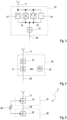
- figure 1 shows a schematic representation of a block diagram of a system 1 for transmitting and receiving radio signals, which is installed in a motor vehicle, for example.
- the system 1 comprises a control unit 30 with a modem 31 and a transmission amplifier module 32 connected to the modem 31, an antenna unit 10 arranged at a distance from the control unit 30 with an antenna 11 and a reception amplifier module 12 connected to the antenna 11, and a control unit 30 and the Antenna unit 10 connecting high-frequency cable 20.
- the system 1 is designed to transmit and receive radio signals with a frequency above 3 GHz and accordingly enables the use of radio services whose frequency bands have high frequencies.
- the transmission path is at the reception amplifier module 12 and the reception path is looped past the transmission amplifier module 32, i.e. the reception amplifier module 12 is not in the transmission path and the transmission amplifier module 32 is not in the reception path.
- figure 2 1 shows a schematic representation of a block diagram of an antenna unit 10 of a system for transmitting and receiving radio signals according to an embodiment of the present invention.
- an amplification factor of the transmission amplifier module 32 (see figure 1 ) and/or the reception amplifier module 12 is equal to or greater than an attenuation factor of the high-frequency cable 20.
- the transmission amplifier module 32 and the reception amplifier module 12 are also dimensioned symmetrically.
- the system also includes a diagnostic unit (not shown) for checking the functionality of the high-frequency cable 20 and is designed to apply a direct current to the receiving amplifier module 12 via the high-frequency cable 20 . It includes a bias tee and a DC blocker (neither shown).
- the antenna unit 10 includes a protection circuit 40 (VSWR protection circuit) for protecting the transmission amplifier module 32 and/or the modem 31.
- the protection circuit 40 includes a protection switch 42 with a reflected power detector, a terminating resistor 41 and a bypass line 43 and is configured a To direct the transmission signal by means of the bypass line 43 to the reception amplifier module 12 over to the antenna 11 or to the terminating resistor 41 when a reflected power detected by the reflected power detector exceeds a predetermined threshold value.
- the protective switch 42 can be embodied as a semiconductor (HL) switch.
- figure 3 1 shows, in a schematic representation, a block diagram of an antenna unit 10 of a system for transmitting and receiving radio signals according to a further embodiment of the present invention.
- the system has the same structure as in figure 2 system shown, wherein the protection circuit 40 is not shown here for the sake of clarity.
- the system includes one or more scalable radio frequency modules that are in the figure 3 are shown as a filter 13, a mixer 14, a switch 15 and a duplexer 16 by way of example only.
- the high-frequency modules are between the antenna 11 and the Looped in receiving amplifier module 12 and are the receiving amplifier module 12 upstream in a receiving direction.
- figure 4 1 shows a schematic representation of a block diagram of an antenna unit 10 of a system for transmitting and receiving radio signals according to a third embodiment of the present invention.
- the system has the same structure as in figure 2 system shown, wherein the protection circuit 40 is not shown here for the sake of clarity.
- the system is designed to send and receive radio signals of different radio services (GSM, UMTS, LTE mobile radio services and Car2X services) and the antenna unit 10 includes a combiner 17, but can also include a frequency multiplexer 18, which in the figure 4 is shown as an alternative.
- GSM Global System for Mobile communications
- UMTS Universal Mobile Telecommunications
- LTE mobile radio services Long Term Evolution
- Car2X Car2X services
- FIG 5 shows a schematic representation of a block diagram of a system 2 for transmitting and receiving radio signals according to a fourth embodiment of the present invention.
- the system 2 includes an actuator 50 for automatically setting an amplification factor of the transmission amplifier module 32 and the reception amplifier module 12.
- the actuator 50 can also be designed to automatically set a usable frequency range or to automatically tune a useful frequency.
- An essential advantage of the system 2 according to the invention for transmitting and receiving radio signals is that, while being versatile in use, it is very robust in relation to different installation situations and thus different lengths of the high-frequency cable 20 . Further advantages can be seen in the simple structure of the system 2 and in the suitability of the system 2 for high frequencies of the radio signals.
Landscapes
- Engineering & Computer Science (AREA)
- Computer Networks & Wireless Communication (AREA)
- Signal Processing (AREA)
- Power Engineering (AREA)
- Transceivers (AREA)
Description
- Die Erfindung betrifft ein System zum Senden und Empfangen von Funksignalen, welches ein Steuergerät mit einem Modem und einem an das Modem angeschlossenen Sendeverstärkermodul, eine zu dem Steuergerät beabstandet angeordnete Antenneneinheit mit einer Antenne und einem an die Antenne angeschlossenen Empfangsverstärkermodul und ein das Steuergerät und die Antenneneinheit verbindendes Hochfrequenzkabel umfasst.
- Beispielsweise offenbaren
US 2007/0264934 A1 ,US 2009/0023477 A1 undUS 2012/0021790 A1 jeweils ein Mobilfunksystem mit einem als eine Basisstation (BTS) ausgebildeten Steuergerät, einer von dem Steuergerät beabstandet angeordneten Antenneneinheit und einem das Steuergerät und die Antenneneinheit verbindendes Hochfrequenzkabel. - Bei derartigen Systemen ist das Modem ausgebildet, mittels der Antenne Funksignale zu senden (transmit, TX) und zu empfangen (receive, RX), und wird daher üblicherweise als TRX-Modem bezeichnet. Um hochfrequente (high frequency, HF) Signale zwischen dem Modem und der Antenne zu übertragen, umfasst das System ein Hochfrequenzkabel, durch welches das Modem und die Antenne miteinander verbunden sind.
- Allerdings werden die Signale bei der Übertragung in dem Hochfrequenzkabel unvermeidlich gedämpft. Die Dämpfung durch das Kabel, die sogenannte Kabeldämpfung, ist dabei desto stärker, je länger das Hochfrequenzkabel einerseits und je höher die Frequenz der Signale andererseits ist. Infolge der Kabeldämpfung kann die Übertragungsqualität leiden, was beispielsweise zu Bitfehlern führt, die sich im Mobilfunk als Call-Drops bemerkbar machen, und die Reichweite sowie die Empfangsqualität einer Funkverbindung verringert sein. Dennoch ist es häufig wünschenswert oder unumgänglich, das TRX-Modem und die Antenne trotz hoher Signalfrequenzen räumlich beabstandet anzuordnen.
- Um in solchen Fällen der Dämpfung der Signale durch das Kabel entgegenzuwirken, werden gewöhnlich Sendeverstärkermodule (power amplifier, PA) und/oder Empfangsverstärkermodule (low noise amplifier, LNA) in den jeweiligen Signalpfad, d.h. Sendepfad bzw. Empfangspfad, eingeschleift. Empfangsverstärkermodule sind zumeist in die Antenneneinheit integriert, um einem Rauschen von empfangenen Signalen entgegenzuwirken, d.h. eine Rauschzahl des Empfangspfads zu verringern. In vielen Fällen sind beispielsweise zugunsten einer einfachen Handhabbarkeit zudem das Empfangsverstärkermodule in die Antenneneinheit integriert.
- Die
EP 0 905 915 A2 offenbart ein solches als Mobilfunkadapter ausgebildetes System. Der Mobilfunkadapter umfasst eine Antenne und jeweils ein benachbart zu der Antenne angeordnetes und an die Antenne angeschlossenes Empfangsverstärkermodul bzw. Sendeverstärkermodul. Ein zu dem Empfangsverstärkermodul beabstandet angeordnetes mobiles Endgerät, ist an den Mobilfunkadapter über zwei Kabel anschließbar, wobei dem Sendepfad und dem Empfangspfad jeweils eines der beiden Kabel ausschließlich zugeordnet ist. - Ein System der eingangs genannten Art kann insbesondere in einem Fahrzeug, zumeist in einem Kraftfahrzeug, verbaut sein, um dem Fahrzeug eine Funkkommunikation beispielsweise mit einem externen Mobilfunknetz, einem externen WLAN-Zugang, einem externen Bluetooth-Gerät oder mit anderen Fahrzeugen zu ermöglichen (Car2X).
- Beispielsweise offenbart die
DE 44 10 542 A1 ein System zum Nutzen eines mobilen Endgeräts in einem Fahrzeug. Das System umfasst eine Außenantenne und ein benachbart zu der Außenantenne angeordnetes und an die Außenantenne angeschlossenes Empfangsverstärkermodul und ein innerhalb des Fahrzeugs angeordnetes Sendeverstärkermodul. Das Empfangsverstärkermodul und das Sendeverstärkermodul sind mittels zweier Koaxialkabel miteinander verbunden, die jeweils dem Sendepfad und dem Empfangspfad ausschließlich zugeordnet sind. - Die
DE 10 2006 021 514 A1 offenbart ein weiteres Mobilfunkteilnehmersystem für ein Fahrzeug mit einer Antenne, einem benachbart zu der Antenne angeordneten und an die Antenne angeschlossenen Empfangsverstärkermodul, einem Koaxialkabel und einem mit dem Empfangsverstärkermodul über das Koaxialkabel verbundenen Sendeverstärkermodul. Das Koaxialkabel ist zugleich dem Sendepfad und dem Empfangspfad zugeordnet. An das Sendeverstärkermodul ist ein mobiles Endgerät anschließbar. -
US 2013/0215804 A1 offenbart ein System mit einem Steuergerät und einer beabstandet zu dem Steuergerät angeordneten Antenneneinheit, welche eine Schutzschaltung gegen eine Fehlfunktion eines bestimmten Bauteils der Antenneneinheit umfasst. - Wenn die Komponenten eines wie vorstehend beschriebenen Systems nicht ausreichend aufeinander abgestimmt sind, kann die Funktion des Systems beeinträchtigt sein oder das Sendeverstärkungsmodul beispielsweise durch Reflexionen in dem Hochfrequenzkabel beschädigt oder zerstört werden. Eine mangelhafte Abstimmung kann sich leicht aus einer konkreten Einbausituation des Systems, einer fehlerhaften Einstellung der Verstärkermodule oder dergleichen ergeben.
- Der Erfindung liegt daher die Aufgabe zugrunde, ein verbessertes System zum Senden und Empfangen von Funksignalen zu schaffen, welches die beschriebenen Nachteile vermeidet und eine große Robustheit aufweist.
- Gegenstand der Erfindung ist ein System zum Senden und Empfangen von Funksignalen, welches ein Steuergerät mit einem Modem und einem an das Modem angeschlossenen Sendeverstärkermodul, eine zu dem Steuergerät beabstandet angeordnete Antenneneinheit mit einer Antenne und einem an die Antenne angeschlossenen Empfangsverstärkermodul und ein das Steuergerät und die Antenneneinheit verbindendes Hochfrequenzkabel umfasst. Das System ist vielseitig verwendbar und kann insbesondere in Kraftfahrzeugen verbaut sein. In diesen Fällen kann es sich bei dem Steuergerät um ein sogenanntes Telematik-Steuergerät handeln. Es versteht sich, dass jeweils der Sendepfad an dem Empfangsverstärkermodul und der Empfangspfad an dem Sendeverstärkermodul vorbei geschleift sind.
- Erfindungsgemäß umfasst die Antenneneinheit eine Schutzschaltung zum Schützen des Sendeverstärkermoduls und/oder des Modems, welche einen Schutzschalter mit einem Reflexionsleistungsdetektor sowie einen Abschlusswiderstand und/oder eine Bypass-Leitung umfasst und welche konfiguriert ist, ein Sendesignal mittels der Bypass-Leitung an dem Empfangsverstärkermodul vorbei zu der Antenne oder zu dem Abschlusswiderstand zu leiten, wenn eine von dem Reflexionsleistungsdetektor detektierte Reflexionsleistung einen vorbestimmten Schwellwert überschreitet. Die Schutzschaltung, auch VSWR (voltage standing wave ratio)-Schutzschaltung genannt, verhindert wirksam, dass das Sendeverstärkermodul oder das Modem im Falle einer mangelhaften Abstimmung durch eine Signalreflektion in dem Hochfrequenzkabel Schaden nehmen. Der Schutzschalter verbindet den Signalausgang des Sendeverstärkermoduls in einem solchen Fall mit dem Abschlusswiderstand (dummy load, üblicherweise 50 Ohm) oder über die Bypass-Leitung mit der Antenne, wenn der Reflexionsleistungsdetektor eine schädliche Reflexionsleistung erfasst. Auf diese Weise wird eine Schädigung oder Zerstörung des Sendeverstärkermoduls oder des Modems effektiv verhindert.
- Das Sendeverstärkermodul ist bei dem Modem angeordnet und nur das Empfangsverstärkermodul in die Antenneneinheit integriert. Diese Anordnung bietet den Vorteil, dass das Sendeverstärkermodul und das Modem schaltungstechnisch integriert, d.h. auf derselben Leiterplatte (printed circuit board, PCB) angeordnet, sein können, wobei das Modem die Steuerung des Sendeverstärkermoduls übernimmt. Entsprechend können sonst externe Steuerleitungen zwischen dem Modem und dem Sendeverstärkermodul entfallen. Zudem kann die Sendeleistung des Modems verringert sein, da die von dem Modem gesendeten Signale vor der Übertragung durch das Hochfrequenzkabel von dem Sendeverstärkermodul verstärkt werden.
- Bevorzugt ist das System zum Senden und Empfangen von Funksignalen mit einer Frequenz oberhalb von 3 GHz ausgebildet. Bei Frequenzen oberhalb von 3 GHz ist die Dämpfung durch das Hochfrequenzkabel sehr stark. Sowohl Frequenzbänder des Mobilfunks (3,5 GHz) als auch Frequenzbänder für die Car2X-Funkkommunikation (5,9 GHz) liegen oberhalb von 3 GHz.
- In einer Ausführungsform ist ein Verstärkungsfaktor des Sendeverstärkermoduls und/oder des Empfangsverstärkermoduls gleich einem oder größer als ein Dämpfungsfaktor des Hochfrequenzkabels, und/oder sind das Sendeverstärkermodul und das Empfangsverstärkermodul symmetrisch dimensioniert. Der Dämpfungsfaktor korrespondiert zu einem Dämpfungsverlust eines Signals in dem Hochfrequenzkabel, also zu einer durch das Kabel verursachten Verlustleistung. Durch eine dem mindestens ebenso großen Verstärkungsfaktor korrespondierende Verstärkungsleistung wird daher die Verlustleistung kompensiert. Die symmetrische Dimensionierung bewirkt eine ausgeglichene Leistungsübertragungsbilanz (link budget) zwischen der Senderichtung und der Empfangsrichtung, was in erster Linie für zertifizierungspflichtige Funkdienste, beispielsweise Bluetooth und Car2X, verlangt wird.
- Vorteilhaft umfasst das System ein Stellglied zum insbesondere automatischen Einstellen eines Verstärkungsfaktors des Sendeverstärkermoduls und/oder des Empfangsverstärkermoduls. Das Stellglied kann als eine Software implementiert sein, um den Verstärkungsfaktor flexibel einstellbar vorzusehen. Auf diese Weise ist der Verstärkungsfaktor kodierbar, d.h. die Verstärkungsleistung des Senderverstärkermoduls und/oder des Empfangsverstärkermoduls ist abhängig von der Dämpfung durch das Hochfrequenzkabel einstellbar. Das Stellglied kann ohne oder mit einer Rückmeldung ausgebildet sein. Im letzten Fall kann das Stellglied mit einem Detektor, welcher die Dämpfung des Hochleistungskabels erfasst, verbunden sein, um einen Regelkreis für den Verstärkungsfaktor zu bilden. Mittels des Regelkreises wird der Verstärkungsfaktor automatisch und dynamisch an unterschiedliche Längen des Hochleistungskabels angepasst.
- Alternativ oder zusätzlich kann das System ein Stellglied zum insbesondere automatischen Einstellen eines nutzbaren Frequenzbereichs umfassen und/oder zum insbesondere automatischen Abstimmen einer Nutzfrequenz ausgebildet sein. Das Stellglied ermöglicht je nach Bandbreite und/oder Anzahl unterstützter Funkdienstkanäle ein Abstimmen, insbesondere Nachregeln (Synchronisieren) des Sendeverstärkermoduls und/oder des Empfangsverstärkermoduls hinsichtlich der jeweils verwendeten Frequenzen (TRX control loop). Das Stellglied kann Teil eines Regelkreises sein, um ein automatisches und dynamisches Abstimmen zu ermöglichen.
- In weiteren Ausführungsformen umfasst die Antenneneinheit ein insbesondere skalierbares Hochfrequenzmodul, insbesondere einen Filter, einen Mischer, einen Schalter oder einen Du-/Triplexer. Die Art und Anzahl der Hochfrequenzmodule richtet sich nach der Bandbreite und/oder der Anzahl unterstützter Funkdienstkanäle.
- Bei diesen Ausführungsformen kann das Hochfrequenzmodul dem Sendeverstärkermodul und/oder dem Empfangsverstärkermodul in einer Senderichtung und/oder in einer Empfangsrichtung vorgeschaltet sein. Mit anderen Worten kann das Hochfrequenzmodul antennenseitig oder modemseitig in den Sendepfad und/oder in den Empfangspfad eingeschleift sein.
- Bevorzugt ist das System zum Senden und Empfangen von Funksignalen unterschiedlicher Funkdienste ausgebildet und umfasst insbesondere die Antenneneinheit einen Kombinierer oder einen Frequenzmultiplexer. Der Kombinierer oder der Frequenzmultiplexer erlauben die Nutzung eines einzigen Hochfrequenzkabels zum gleichzeitigen bzw. parallelen Übertragen von Funksignalen unterschiedlicher Funkdienste, d.h. unterschiedlicher Frequenzen und Bandbreiten (GSM-, UMTS-, LTE-Mobilfunkdienste und Car2X-Dienste).
- In einer Ausführungsform umfasst das System eine Diagnoseeinheit zum Prüfen einer Funktionsfähigkeit des Hochfrequenzkabels. Die Diagnoseeinheit kann auf einer Gleichstrom (DC)-Widerstandsmessung beruhen. Alternativ kann die Diagnoseeinheit ein Stromfenster oder ein pulsweitenmoduliertes (pulse width modulation) Signal zu Messzwecken verwenden. Mittels der Diagnoseeinheit kann eine Unterbrechung, ein Kurzschluss oder eine Quetschung des Hochfrequenzkabels auf seiner Einbaustrecke (Fernverbau) zuverlässig erkannt werden.
- In weiteren Ausführungsformen ist das System konfiguriert, das Empfangsverstärkermodul über das Hochfrequenzkabel mit einem Gleichstrom zu beaufschlagen, und umfasst insbesondere ein Bias-T (auch als Bias-Tee bezeichnet) und/oder einen Gleichstromblocker (DC blocker). Dies ermöglicht, eine Versorgung der Antenneneinheit durch das Steuergerät, ohne die Antenneneinheit mit einem separaten Stromkabel zu verbinden. Auf diese Weise muss die Antenneneinheit beispielsweise in einem Fahrzeug nicht eigens an das Bordnetz angeschlossen sein.
- Die Erfindung ist anhand von Ausführungsformen in den Zeichnungen schematisch dargestellt und wird unter Bezugnahme auf die Zeichnungen weiter beschrieben. Es zeigt:
- Figur 1
- in einer schematischen Darstellung ein Blockschaltbild eines Systems zum Senden und Empfangen von Funksignalen;
- Figur 2
- in einer schematischen Darstellung ein Blockschaltbild einer Antenneneinheit eines Systems zum Senden und Empfangen von Funksignalen gemäß einer Ausführungsform der vorliegenden Erfindung;
- Figur 3
- in einer schematischen Darstellung ein Blockschaltbild einer Antenneneinheit eines Systems zum Senden und Empfangen von Funksignalen gemäß einer weiteren Ausführungsform der vorliegenden Erfindung;
- Figur 4
- in einer schematischen Darstellung ein Blockschaltbild einer Antenneneinheit eines Systems zum Senden und Empfangen von Funksignalen gemäß einer dritten Ausführungsform der vorliegenden Erfindung;
- Figur 5
- in einer schematischen Darstellung ein Blockschaltbild eines Systems zum Senden und Empfangen von Funksignalen gemäß einer vierten Ausführungsform der vorliegenden Erfindung.
-
Figur 1 zeigt in einer schematischen Darstellung ein Blockschaltbild eines Systems 1 zum Senden und Empfangen von Funksignalen, das beispielsweise in einem Kraftfahrzeug verbaut ist. - Das System 1 umfasst ein Steuergerät 30 mit einem Modem 31 und einem an das Modem 31 angeschlossenen Sendeverstärkermodul 32, eine zu dem Steuergerät 30 beabstandet angeordnete Antenneneinheit 10 mit einer Antenne 11 und einem an die Antenne 11 angeschlossenen Empfangsverstärkermodul 12 und ein das Steuergerät 30 und die Antenneneinheit 10 verbindendes Hochfrequenzkabel 20. Das System 1 ist zum Senden und Empfangen von Funksignalen mit einer Frequenz oberhalb von 3 GHz ausgebildet ist und ermöglicht entsprechend die Nutzung auch solcher Funkdienste, deren Frequenzbänder hohe Frequenzen aufweisen. Der Sendepfad ist an dem Empfangsverstärkermodul 12, und der Empfangspfad ist an dem Sendeverstärkermodul 32 vorbei geschleift, d.h. das Empfangsverstärkermodul 12 liegt nicht im Sendepfad, und das Sendeverstärkermodul 32 liegt nicht im Empfangspfad.
-
Figur 2 zeigt in einer schematischen Darstellung ein Blockschaltbild einer Antenneneinheit 10 eines Systems zum Senden und Empfangen von Funksignalen gemäß einer Ausführungsform der vorliegenden Erfindung. - Bei dem System ist ein Verstärkungsfaktor des Sendeverstärkermoduls 32 (s.
Figur 1 ) und/oder des Empfangsverstärkermoduls 12 gleich einem oder größer als ein Dämpfungsfaktor des Hochfrequenzkabels 20. Das Sendeverstärkermodul 32 und das Empfangsverstärkermodul 12 sind überdies symmetrisch dimensioniert. - Das System umfasst ferner eine Diagnoseeinheit (nicht abgebildet) zum Prüfen einer Funktionsfähigkeit des Hochfrequenzkabels 20 und ist ausgebildet, das Empfangsverstärkermodul 12 über das Hochfrequenzkabel 20 mit einem Gleichstrom zu beaufschlagen. Dazu umfasst es ein Bias-T sowie einen Gleichstromblocker (beide nicht abgebildet).
- Weiterhin umfasst die Antenneneinheit 10 eine Schutzschaltung 40 (VSWR-Schutzschaltung) zum Schützen des Sendeverstärkermoduls 32 und/oder des Modems 31. Die Schutzschaltung 40 umfasst einen Schutzschalter 42 mit einem Reflexionsleistungsdetektor, einem Abschlusswiderstand 41 und eine Bypass-Leitung 43 und ist konfiguriert, ein Sendesignal mittels der Bypass-Leitung 43 an dem Empfangsverstärkermodul 12 vorbei zu der Antenne 11 oder zu dem Abschlusswiderstand 41 zu leiten, wenn eine von dem Reflexionsleistungsdetektor detektierte Reflexionsleistung einen vorbestimmten Schwellwert überschreitet. Der Schutzschalter 42 kann als ein Halbleiter (HL)-Schalter ausgebildet sein.
-
Figur 3 zeigt in einer schematischen Darstellung ein Blockschaltbild einer Antenneneinheit 10 eines Systems zum Senden und Empfangen von Funksignalen gemäß einer weiteren Ausführungsform der vorliegenden Erfindung. Das System hat denselben Aufbau wie das inFigur 2 gezeigte System, wobei die Schutzschaltung 40 der Übersicht halber hier nicht abgebildet ist. - Das System umfasst ein oder mehrere skalierbare Hochfrequenzmodule, die in der
Figur 3 lediglich beispielhaft als ein Filter 13, ein Mischer 14, ein Schalter 15 und ein Du-/Triplexer 16 abgebildet sind. Die Hochfrequenzmodule sind zwischen der Antenne 11 und dem Empfangsverstärkermodul 12 eingeschleift und sind dem Empfangsverstärkermodul 12 in einer Empfangsrichtung vorgeschaltet. -
Figur 4 zeigt in einer schematischen Darstellung ein Blockschaltbild einer Antenneneinheit 10 eines Systems zum Senden und Empfangen von Funksignalen gemäß einer dritten Ausführungsform der vorliegenden Erfindung. Das System hat denselben Aufbau wie das inFigur 2 gezeigte System, wobei die Schutzschaltung 40 der Übersicht halber hier nicht abgebildet ist. - Das System ist zum Senden und Empfangen von Funksignalen unterschiedlicher Funkdienste (GSM-, UMTS-, LTE-Mobilfunkdienste und Car2X-Dienste) ausgebildet und die Antenneneinheit 10 umfasst einen Kombinierer 17, kann aber auch einen Frequenzmultiplexer 18 umfassen, welcher in der
Figur 4 als eine Alternative abgebildet ist. -
Figur 5 zeigt in einer schematischen Darstellung ein Blockschaltbild eines Systems 2 zum Senden und Empfangen von Funksignalen gemäß einer vierten Ausführungsform der vorliegenden Erfindung. Das System 2 umfasst ein Stellglied 50 zum automatischen Einstellen eines Verstärkungsfaktors des Sendeverstärkermoduls 32 und des Empfangsverstärkermoduls 12. Alternativ oder zusätzlich kann das Stellglied 50 auch zum automatischen Einstellen eines nutzbaren Frequenzbereichs oder zum automatischen Abstimmen einer Nutzfrequenz ausgebildet sein. - Ein wesentlicher Vorteil des erfindungsgemäßen Systems 2 zum Senden und Empfangen von Funksignalen besteht darin, dass es bei vielseitiger Verwendbarkeit eine große Robustheit gegenüber unterschiedlichen Einbausituationen und damit Längen des Hochfrequenzkabels 20 aufweist. Weitere Vorteile sind in der einfachen Struktur des Systems 2 und in der Eignung des Systems 2 für hohe Frequenzen der Funksignale zu sehen.
-
- 1
- System
- 2
- System
- 10
- Antenneneinheit
- 11
- Antenne
- 12
- Empfangsverstärkermodul
- 13
- Filter
- 14
- Mischer
- 15
- Schalter
- 16
- Du-/Triplexer
- 17
- Kombinierer
- 18
- Frequenzmultiplexer
- 20
- Hochfrequenzkabel
- 30
- Steuergerät
- 31
- Modem
- 32
- Sendeverstärkermodul
- 40
- Schutzschaltung
- 41
- Abschlusswiderstand
- 42
- Schutzschalter
- 43
- Bypass-Leitung
- 50
- Stellglied
Claims (14)
- System (1) zum Senden und Empfangen von Funksignalen, welches ein Steuergerät (30) mit einem Modem (31) und einem an das Modem (31) angeschlossenen Sendeverstärkermodul (32), eine zu dem Steuergerät (30) beabstandet angeordnete Antenneneinheit (10) mit einer Antenne (11) und einem an die Antenne (11) angeschlossenen Empfangsverstärkermodul (12) und ein das Steuergerät (30) und die Antenneneinheit (10) verbindendes Hochfrequenzkabel (20) umfasst, wobei die Antenneneinheit (10) eine Schutzschaltung (40) zum Schützen des Sendeverstärkermoduls (32) oder des Modems (31) umfasst, welche einen Schutzschalter (42) mit einem Reflexionsleistungsdetektor sowie einen Abschlusswiderstand (41) umfasst, gekennzeichnet durch eine Bypass-Leitung (43) und dadurch, dass die Schutzschaltung konfiguriert ist, ein Sendesignal mittels der Bypass-Leitung (43) an dem Empfangsverstärkermodul (12) vorbei zu der Antenne (11) oder zu dem Abschlusswiderstand (41) zu leiten, wenn eine von dem Reflexionsleistungsdetektor detektierte Reflexionsleistung einen vorbestimmten Schwellwert überschreitet.
- System nach Anspruch 1, welches zum Senden und Empfangen von Funksignalen mit einer Frequenz oberhalb von 3 GHz ausgebildet ist.
- System nach Anspruch 1 oder 2, bei dem ein Verstärkungsfaktor des Sendeverstärkermoduls (32) oder des Empfangsverstärkermoduls (12) gleich einem oder größer als ein Dämpfungsfaktor des Hochfrequenzkabels (20) ist.
- System nach einem der Ansprüche 1 bis 3, bei dem das Sendeverstärkermodul (32) und das Empfangsverstärkermodul (12) symmetrisch dimensioniert sind.
- System nach einem der Ansprüche 1 bis 4, welches ein Stellglied (50) zum Einstellen eines Verstärkungsfaktors des Sendeverstärkermoduls (32) oder des Empfangsverstärkermoduls (12) umfasst.
- System nach einem der Ansprüche 1 bis 5, welches ein Stellglied (50) zum Einstellen eines nutzbaren Frequenzbereichs umfasst oder zum Abstimmen einer Nutzfrequenz ausgebildet ist.
- System nach einem der Ansprüche 1 bis 6, bei dem die Antenneneinheit (10) ein Hochfrequenzmodul umfasst.
- System nach Anspruch 7, bei dem das Hochfrequenzmodul als ein Filter (13), ein Mischer (14), ein Schalter (15) oder ein Du-/Triplexer (16) ausgebildet ist.
- System nach Anspruch 7 oder 8, bei dem das Hochfrequenzmodul dem Sendeverstärkermodul (32) oder dem Empfangsverstärkermodul (12) in einer Senderichtung oder in einer Empfangsrichtung vorgeschaltet ist.
- System nach einem der Ansprüche 1 bis 9, welches zum Senden und Empfangen von Funksignalen unterschiedlicher Funkdienste ausgebildet ist.
- System nach Anspruch 10, bei dem die Antenneneinheit (10) einen Kombinierer (17) oder einen Frequenzmultiplexer (18) umfasst.
- System nach einem der Ansprüche 1 bis 11, welches eine Diagnoseeinheit zum Prüfen einer Funktionsfähigkeit des Hochfrequenzkabels (20) umfasst.
- System nach einem der Ansprüche 1 bis 12, welches ausgebildet ist, das Empfangsverstärkermodul (12) über das Hochfrequenzkabel (20) mit einem Gleichstrom zu beaufschlagen.
- System nach Anspruch 13, welches ein Bias-T oder einen Gleichstromblocker umfasst.
Priority Applications (1)
| Application Number | Priority Date | Filing Date | Title |
|---|---|---|---|
| EP23158348.5A EP4203335A3 (de) | 2018-08-03 | 2019-07-17 | Sende-/empfangssystem für funksignale mit getrennten sende- und empfangspfaden |
Applications Claiming Priority (2)
| Application Number | Priority Date | Filing Date | Title |
|---|---|---|---|
| DE102018213029.9A DE102018213029A1 (de) | 2018-08-03 | 2018-08-03 | Sende-/Empfangssystem für Funksignale |
| PCT/EP2019/069260 WO2020025327A1 (de) | 2018-08-03 | 2019-07-17 | Sende-/empfangssystem für funksignale mit integrierter sendeverstärker-schutzfunktion |
Related Child Applications (2)
| Application Number | Title | Priority Date | Filing Date |
|---|---|---|---|
| EP23158348.5A Division EP4203335A3 (de) | 2018-08-03 | 2019-07-17 | Sende-/empfangssystem für funksignale mit getrennten sende- und empfangspfaden |
| EP23158348.5A Division-Into EP4203335A3 (de) | 2018-08-03 | 2019-07-17 | Sende-/empfangssystem für funksignale mit getrennten sende- und empfangspfaden |
Publications (2)
| Publication Number | Publication Date |
|---|---|
| EP3830963A1 EP3830963A1 (de) | 2021-06-09 |
| EP3830963B1 true EP3830963B1 (de) | 2023-09-06 |
Family
ID=67390069
Family Applications (2)
| Application Number | Title | Priority Date | Filing Date |
|---|---|---|---|
| EP19742343.7A Active EP3830963B1 (de) | 2018-08-03 | 2019-07-17 | Sende-/empfangssystem für funksignale mit integrierter sendeverstärker-schutzfunktion |
| EP23158348.5A Pending EP4203335A3 (de) | 2018-08-03 | 2019-07-17 | Sende-/empfangssystem für funksignale mit getrennten sende- und empfangspfaden |
Family Applications After (1)
| Application Number | Title | Priority Date | Filing Date |
|---|---|---|---|
| EP23158348.5A Pending EP4203335A3 (de) | 2018-08-03 | 2019-07-17 | Sende-/empfangssystem für funksignale mit getrennten sende- und empfangspfaden |
Country Status (5)
| Country | Link |
|---|---|
| US (1) | US11394411B2 (de) |
| EP (2) | EP3830963B1 (de) |
| CN (1) | CN112567634B (de) |
| DE (1) | DE102018213029A1 (de) |
| WO (1) | WO2020025327A1 (de) |
Families Citing this family (2)
| Publication number | Priority date | Publication date | Assignee | Title |
|---|---|---|---|---|
| CN113572493B (zh) * | 2020-11-04 | 2022-09-23 | 中兴通讯股份有限公司 | 信号收发装置、信号放大装置、通信系统的运行方法 |
| CN117095582B (zh) * | 2023-08-29 | 2026-04-24 | 湖南六九零六信息科技股份有限公司 | 一种短波通信装备实训平台 |
Family Cites Families (21)
| Publication number | Priority date | Publication date | Assignee | Title |
|---|---|---|---|---|
| FR2699008B1 (fr) * | 1992-12-04 | 1994-12-30 | Alcatel Espace | Antenne active à synthèse de polarisation variable. |
| DE4410542B4 (de) | 1994-03-26 | 2004-07-22 | Fuba Automotive Gmbh & Co. Kg | Anordnung für den Betrieb von Funkgeräten |
| JPH08330996A (ja) * | 1995-05-30 | 1996-12-13 | Sony Corp | アンテナ共用器 |
| DE19547288C2 (de) * | 1995-12-18 | 1999-03-18 | Siemens Ag | Funkstation mit einer abgesetzten Antenneneinheit |
| EP0899980A1 (de) * | 1997-08-28 | 1999-03-03 | Siemens Aktiengesellschaft | Telekommunikationsnetzwerk und Zustand-Propagierungsverfahren |
| US6459915B2 (en) * | 1997-09-02 | 2002-10-01 | Matsushita Electric Industrial Co. Ltd. | External adapter for a portable cellular phone |
| US6658269B1 (en) * | 1999-10-01 | 2003-12-02 | Raytheon Company | Wireless communications system |
| EP1279046B1 (de) * | 2000-04-07 | 2007-04-04 | The Chief Controller, Research and Development, Defence Research and Development Organisation of Ministry of Defence | Sende-/empfängermodul für aktivphasenarrayantenne |
| DE102006021514A1 (de) | 2006-05-04 | 2007-11-15 | Funkwerk Dabendorf Gmbh | Anordnung zur Übertragung von Signalen über eine Antennenzuleitung in einer Mobilfunk-Teilnehmerstation |
| US7616940B2 (en) * | 2006-05-10 | 2009-11-10 | Nortel Network Limited | Stand-alone low noise amplifier |
| US7880670B2 (en) | 2007-06-18 | 2011-02-01 | AGC Automotive | Signal measurement system and method for testing an RF component |
| US20090023477A1 (en) | 2007-07-19 | 2009-01-22 | Telefonaktiebolaget Lm Ericsson (Publ) | Method and apparatus for reconfiguring a multi-sector base station |
| CN102365829B (zh) | 2009-03-27 | 2015-04-22 | 西门子公司 | 用于基站与天线之间的通信的无线电通信系统和方法 |
| KR101108143B1 (ko) | 2010-05-19 | 2012-02-27 | 한국광성전자 주식회사 | 튜너부 및 액티브안테나가 일체형 모듈로 통합된 카오디오 시스템 |
| WO2012079187A1 (en) * | 2010-12-13 | 2012-06-21 | Telefonaktiebolaget L M Ericsson (Publ) | A base station subsystem, a rbs part and a tma part and methods thereof for synchronizing the rbs part and the tma part |
| US20130015923A1 (en) * | 2011-07-13 | 2013-01-17 | Lockheed Martin Corporation | Automatic waveguide switch-based protection systems for receiver circuitry |
| US10231201B2 (en) * | 2014-12-08 | 2019-03-12 | Nextnav, Llc | Systems and methods for assured time synchronization of an RF beacon |
| US20180019733A1 (en) * | 2016-07-14 | 2018-01-18 | Qualcomm Incorporated | Multi-level clock gate controls to address scan mode power droop and voltage bump requirement |
| US10211795B2 (en) * | 2016-07-21 | 2019-02-19 | Skyworks Solutions, Inc. | Impedance transformation circuit and overload protection for low noise amplifier |
| US9866259B1 (en) * | 2016-11-23 | 2018-01-09 | Infineon Technologies Ag | Transmitter/receiver module for millimeter wave 5G MIMO communication systems |
| US10594268B2 (en) * | 2018-05-18 | 2020-03-17 | Cree, Inc. | Switch circuits having integrated overdrive protection and related transmit/receive circuits and MMIC amplifiers |
-
2018
- 2018-08-03 DE DE102018213029.9A patent/DE102018213029A1/de not_active Withdrawn
-
2019
- 2019-07-17 WO PCT/EP2019/069260 patent/WO2020025327A1/de not_active Ceased
- 2019-07-17 US US17/263,445 patent/US11394411B2/en active Active
- 2019-07-17 EP EP19742343.7A patent/EP3830963B1/de active Active
- 2019-07-17 EP EP23158348.5A patent/EP4203335A3/de active Pending
- 2019-07-17 CN CN201980051542.2A patent/CN112567634B/zh active Active
Also Published As
| Publication number | Publication date |
|---|---|
| EP4203335A2 (de) | 2023-06-28 |
| EP3830963A1 (de) | 2021-06-09 |
| CN112567634B (zh) | 2022-04-29 |
| WO2020025327A1 (de) | 2020-02-06 |
| DE102018213029A1 (de) | 2020-02-06 |
| US20210273666A1 (en) | 2021-09-02 |
| EP4203335A3 (de) | 2023-09-13 |
| CN112567634A (zh) | 2021-03-26 |
| US11394411B2 (en) | 2022-07-19 |
Similar Documents
| Publication | Publication Date | Title |
|---|---|---|
| EP1329030B1 (de) | Multiband-endgerät | |
| EP1841083B1 (de) | Mehrbandfähige Schaltungsanordnung zur Kompensation der in Signalwegen zu einer Antenne auftretenden Dämpfung | |
| WO2010121914A1 (de) | Frontendmodul mit antennentuner | |
| DE19610760A1 (de) | Sende-Empfangs-Umschalter mit Halbleitern | |
| EP3707834B1 (de) | Verfahren und vorrichtungen zur ermittlung eines frequenzbereichs eines zu übertragenden signals | |
| DE10233123A1 (de) | Einrichtung zur dynamischen Anpassung der Impedanz zwischen einem Leistungsverstärker und einer Antenne | |
| WO2012045526A1 (de) | Vorrichtung zur drahtlosen informationsübertragung, kommunikationsendgerät zur drahtlosen informationsübertragung sowie verfahren zur impedanzanpassung | |
| EP4203335A2 (de) | Sende-/empfangssystem für funksignale mit getrennten sende- und empfangspfaden | |
| EP1168500A2 (de) | Antennenumschalter für Sende-Empfangseinheiten in einer Mobilstation | |
| DE69601044T2 (de) | Sende- und Empfangsgerät | |
| EP3642964B1 (de) | Verfahren und vorrichtungen zur verstärkung von funksignalen zwischen einem endgerät und einer antenne | |
| DE10345971B4 (de) | Mobilfunk-Sendeempfangseinrichtung | |
| EP1371144A1 (de) | Schaltungsanordnung zum kompensieren der dämpfung in einem antennenzuleitungskabel für ein mobilfunkgerät | |
| DE102017131088B4 (de) | Mobilfunkkompensator zum Einsatz in Kraftfahrzeugen und ein solches Kraftfahrzeug | |
| DE19913064C1 (de) | Schaltungsanordnung zur Dämpfungskompensation | |
| EP1151536B1 (de) | Verfahren und anordnung zur leistungsregelung eines sendeverstärkers | |
| DE102013000270B4 (de) | Kompensationsverstärkungsschaltung zum Einbau in eine Übertragungsleitung zwischen einem in einem Kraftfahrzeug befindlichen Mobilfunkgerät bzw. einer kraftfahrzeugseitigen Aufnahme für das Mobilfunkgerät einerseits und einer Antenne des Kraftfahrzeugs andererseits und Verfahren zum Betrieb einer entsprechenden bidirektionalen Kompensationsverstärkungsschaltung | |
| DE102013111798B4 (de) | Duplexer | |
| DE102012006362B4 (de) | Verfahren und Vorrichtung zur Übertragung von Daten mit hohen Datenraten auf Koaxialleitungen | |
| EP0874473B1 (de) | Leistungregelung für eine Funk-Kommunikations-Anordnung | |
| DE102010045244A1 (de) | Kompensation der Dämpfung in einer Hochfrequenzleitung zwischen einer Mobilfunkstation und einer Antenne | |
| EP4250575A1 (de) | Vorrichtung und verfahren zur datenübertragung | |
| DE102005058668B4 (de) | Verfahren zum Betreiben eines Kommunikationsendgeräts | |
| DE19954286A1 (de) | Mobiles Telekommunikationsendgerät | |
| EP1815602A1 (de) | Anordung zum anschalten von zumindest einer sendeeinheit an eine sende-empfangsantenne |
Legal Events
| Date | Code | Title | Description |
|---|---|---|---|
| STAA | Information on the status of an ep patent application or granted ep patent |
Free format text: STATUS: UNKNOWN |
|
| STAA | Information on the status of an ep patent application or granted ep patent |
Free format text: STATUS: THE INTERNATIONAL PUBLICATION HAS BEEN MADE |
|
| PUAI | Public reference made under article 153(3) epc to a published international application that has entered the european phase |
Free format text: ORIGINAL CODE: 0009012 |
|
| STAA | Information on the status of an ep patent application or granted ep patent |
Free format text: STATUS: REQUEST FOR EXAMINATION WAS MADE |
|
| 17P | Request for examination filed |
Effective date: 20210125 |
|
| AK | Designated contracting states |
Kind code of ref document: A1 Designated state(s): AL AT BE BG CH CY CZ DE DK EE ES FI FR GB GR HR HU IE IS IT LI LT LU LV MC MK MT NL NO PL PT RO RS SE SI SK SM TR |
|
| DAV | Request for validation of the european patent (deleted) | ||
| DAX | Request for extension of the european patent (deleted) | ||
| GRAP | Despatch of communication of intention to grant a patent |
Free format text: ORIGINAL CODE: EPIDOSNIGR1 |
|
| STAA | Information on the status of an ep patent application or granted ep patent |
Free format text: STATUS: GRANT OF PATENT IS INTENDED |
|
| RIC1 | Information provided on ipc code assigned before grant |
Ipc: H03F 3/24 20060101ALI20230206BHEP Ipc: H03F 3/189 20060101ALI20230206BHEP Ipc: H04W 88/08 20090101ALI20230206BHEP Ipc: H04B 1/48 20060101ALI20230206BHEP Ipc: H04B 1/18 20060101ALI20230206BHEP Ipc: H04B 1/74 20060101ALI20230206BHEP Ipc: H04B 1/3822 20150101ALI20230206BHEP Ipc: H03F 1/52 20060101ALI20230206BHEP Ipc: H04B 1/04 20060101AFI20230206BHEP |
|
| INTG | Intention to grant announced |
Effective date: 20230220 |
|
| GRAS | Grant fee paid |
Free format text: ORIGINAL CODE: EPIDOSNIGR3 |
|
| P01 | Opt-out of the competence of the unified patent court (upc) registered |
Effective date: 20230529 |
|
| GRAA | (expected) grant |
Free format text: ORIGINAL CODE: 0009210 |
|
| STAA | Information on the status of an ep patent application or granted ep patent |
Free format text: STATUS: THE PATENT HAS BEEN GRANTED |
|
| AK | Designated contracting states |
Kind code of ref document: B1 Designated state(s): AL AT BE BG CH CY CZ DE DK EE ES FI FR GB GR HR HU IE IS IT LI LT LU LV MC MK MT NL NO PL PT RO RS SE SI SK SM TR |
|
| REG | Reference to a national code |
Ref country code: GB Ref legal event code: FG4D Free format text: NOT ENGLISH |
|
| REG | Reference to a national code |
Ref country code: CH Ref legal event code: EP |
|
| REG | Reference to a national code |
Ref country code: DE Ref legal event code: R096 Ref document number: 502019009277 Country of ref document: DE |
|
| REG | Reference to a national code |
Ref country code: IE Ref legal event code: FG4D Free format text: LANGUAGE OF EP DOCUMENT: GERMAN |
|
| REG | Reference to a national code |
Ref country code: LT Ref legal event code: MG9D |
|
| REG | Reference to a national code |
Ref country code: NL Ref legal event code: MP Effective date: 20230906 |
|
| PG25 | Lapsed in a contracting state [announced via postgrant information from national office to epo] |
Ref country code: GR Free format text: LAPSE BECAUSE OF FAILURE TO SUBMIT A TRANSLATION OF THE DESCRIPTION OR TO PAY THE FEE WITHIN THE PRESCRIBED TIME-LIMIT Effective date: 20231207 |
|
| PG25 | Lapsed in a contracting state [announced via postgrant information from national office to epo] |
Ref country code: SE Free format text: LAPSE BECAUSE OF FAILURE TO SUBMIT A TRANSLATION OF THE DESCRIPTION OR TO PAY THE FEE WITHIN THE PRESCRIBED TIME-LIMIT Effective date: 20230906 Ref country code: RS Free format text: LAPSE BECAUSE OF FAILURE TO SUBMIT A TRANSLATION OF THE DESCRIPTION OR TO PAY THE FEE WITHIN THE PRESCRIBED TIME-LIMIT Effective date: 20230906 Ref country code: NO Free format text: LAPSE BECAUSE OF FAILURE TO SUBMIT A TRANSLATION OF THE DESCRIPTION OR TO PAY THE FEE WITHIN THE PRESCRIBED TIME-LIMIT Effective date: 20231206 Ref country code: LV Free format text: LAPSE BECAUSE OF FAILURE TO SUBMIT A TRANSLATION OF THE DESCRIPTION OR TO PAY THE FEE WITHIN THE PRESCRIBED TIME-LIMIT Effective date: 20230906 Ref country code: LT Free format text: LAPSE BECAUSE OF FAILURE TO SUBMIT A TRANSLATION OF THE DESCRIPTION OR TO PAY THE FEE WITHIN THE PRESCRIBED TIME-LIMIT Effective date: 20230906 Ref country code: HR Free format text: LAPSE BECAUSE OF FAILURE TO SUBMIT A TRANSLATION OF THE DESCRIPTION OR TO PAY THE FEE WITHIN THE PRESCRIBED TIME-LIMIT Effective date: 20230906 Ref country code: GR Free format text: LAPSE BECAUSE OF FAILURE TO SUBMIT A TRANSLATION OF THE DESCRIPTION OR TO PAY THE FEE WITHIN THE PRESCRIBED TIME-LIMIT Effective date: 20231207 Ref country code: FI Free format text: LAPSE BECAUSE OF FAILURE TO SUBMIT A TRANSLATION OF THE DESCRIPTION OR TO PAY THE FEE WITHIN THE PRESCRIBED TIME-LIMIT Effective date: 20230906 |
|
| PG25 | Lapsed in a contracting state [announced via postgrant information from national office to epo] |
Ref country code: NL Free format text: LAPSE BECAUSE OF FAILURE TO SUBMIT A TRANSLATION OF THE DESCRIPTION OR TO PAY THE FEE WITHIN THE PRESCRIBED TIME-LIMIT Effective date: 20230906 |
|
| PG25 | Lapsed in a contracting state [announced via postgrant information from national office to epo] |
Ref country code: IS Free format text: LAPSE BECAUSE OF FAILURE TO SUBMIT A TRANSLATION OF THE DESCRIPTION OR TO PAY THE FEE WITHIN THE PRESCRIBED TIME-LIMIT Effective date: 20240106 |
|
| PG25 | Lapsed in a contracting state [announced via postgrant information from national office to epo] |
Ref country code: ES Free format text: LAPSE BECAUSE OF FAILURE TO SUBMIT A TRANSLATION OF THE DESCRIPTION OR TO PAY THE FEE WITHIN THE PRESCRIBED TIME-LIMIT Effective date: 20230906 |
|
| PG25 | Lapsed in a contracting state [announced via postgrant information from national office to epo] |
Ref country code: SM Free format text: LAPSE BECAUSE OF FAILURE TO SUBMIT A TRANSLATION OF THE DESCRIPTION OR TO PAY THE FEE WITHIN THE PRESCRIBED TIME-LIMIT Effective date: 20230906 Ref country code: RO Free format text: LAPSE BECAUSE OF FAILURE TO SUBMIT A TRANSLATION OF THE DESCRIPTION OR TO PAY THE FEE WITHIN THE PRESCRIBED TIME-LIMIT Effective date: 20230906 Ref country code: IS Free format text: LAPSE BECAUSE OF FAILURE TO SUBMIT A TRANSLATION OF THE DESCRIPTION OR TO PAY THE FEE WITHIN THE PRESCRIBED TIME-LIMIT Effective date: 20240106 Ref country code: ES Free format text: LAPSE BECAUSE OF FAILURE TO SUBMIT A TRANSLATION OF THE DESCRIPTION OR TO PAY THE FEE WITHIN THE PRESCRIBED TIME-LIMIT Effective date: 20230906 Ref country code: EE Free format text: LAPSE BECAUSE OF FAILURE TO SUBMIT A TRANSLATION OF THE DESCRIPTION OR TO PAY THE FEE WITHIN THE PRESCRIBED TIME-LIMIT Effective date: 20230906 Ref country code: CZ Free format text: LAPSE BECAUSE OF FAILURE TO SUBMIT A TRANSLATION OF THE DESCRIPTION OR TO PAY THE FEE WITHIN THE PRESCRIBED TIME-LIMIT Effective date: 20230906 Ref country code: PT Free format text: LAPSE BECAUSE OF FAILURE TO SUBMIT A TRANSLATION OF THE DESCRIPTION OR TO PAY THE FEE WITHIN THE PRESCRIBED TIME-LIMIT Effective date: 20240108 Ref country code: SK Free format text: LAPSE BECAUSE OF FAILURE TO SUBMIT A TRANSLATION OF THE DESCRIPTION OR TO PAY THE FEE WITHIN THE PRESCRIBED TIME-LIMIT Effective date: 20230906 |
|
| PG25 | Lapsed in a contracting state [announced via postgrant information from national office to epo] |
Ref country code: PL Free format text: LAPSE BECAUSE OF FAILURE TO SUBMIT A TRANSLATION OF THE DESCRIPTION OR TO PAY THE FEE WITHIN THE PRESCRIBED TIME-LIMIT Effective date: 20230906 Ref country code: IT Free format text: LAPSE BECAUSE OF FAILURE TO SUBMIT A TRANSLATION OF THE DESCRIPTION OR TO PAY THE FEE WITHIN THE PRESCRIBED TIME-LIMIT Effective date: 20230906 |
|
| REG | Reference to a national code |
Ref country code: DE Ref legal event code: R097 Ref document number: 502019009277 Country of ref document: DE |
|
| PG25 | Lapsed in a contracting state [announced via postgrant information from national office to epo] |
Ref country code: DK Free format text: LAPSE BECAUSE OF FAILURE TO SUBMIT A TRANSLATION OF THE DESCRIPTION OR TO PAY THE FEE WITHIN THE PRESCRIBED TIME-LIMIT Effective date: 20230906 |
|
| PLBE | No opposition filed within time limit |
Free format text: ORIGINAL CODE: 0009261 |
|
| STAA | Information on the status of an ep patent application or granted ep patent |
Free format text: STATUS: NO OPPOSITION FILED WITHIN TIME LIMIT |
|
| PG25 | Lapsed in a contracting state [announced via postgrant information from national office to epo] |
Ref country code: DK Free format text: LAPSE BECAUSE OF FAILURE TO SUBMIT A TRANSLATION OF THE DESCRIPTION OR TO PAY THE FEE WITHIN THE PRESCRIBED TIME-LIMIT Effective date: 20230906 Ref country code: SI Free format text: LAPSE BECAUSE OF FAILURE TO SUBMIT A TRANSLATION OF THE DESCRIPTION OR TO PAY THE FEE WITHIN THE PRESCRIBED TIME-LIMIT Effective date: 20230906 |
|
| 26N | No opposition filed |
Effective date: 20240607 |
|
| PG25 | Lapsed in a contracting state [announced via postgrant information from national office to epo] |
Ref country code: BG Free format text: LAPSE BECAUSE OF FAILURE TO SUBMIT A TRANSLATION OF THE DESCRIPTION OR TO PAY THE FEE WITHIN THE PRESCRIBED TIME-LIMIT Effective date: 20230906 |
|
| PG25 | Lapsed in a contracting state [announced via postgrant information from national office to epo] |
Ref country code: BG Free format text: LAPSE BECAUSE OF FAILURE TO SUBMIT A TRANSLATION OF THE DESCRIPTION OR TO PAY THE FEE WITHIN THE PRESCRIBED TIME-LIMIT Effective date: 20230906 |
|
| PG25 | Lapsed in a contracting state [announced via postgrant information from national office to epo] |
Ref country code: MC Free format text: LAPSE BECAUSE OF FAILURE TO SUBMIT A TRANSLATION OF THE DESCRIPTION OR TO PAY THE FEE WITHIN THE PRESCRIBED TIME-LIMIT Effective date: 20230906 |
|
| REG | Reference to a national code |
Ref country code: CH Ref legal event code: PL |
|
| PG25 | Lapsed in a contracting state [announced via postgrant information from national office to epo] |
Ref country code: LU Free format text: LAPSE BECAUSE OF NON-PAYMENT OF DUE FEES Effective date: 20240717 |
|
| PG25 | Lapsed in a contracting state [announced via postgrant information from national office to epo] |
Ref country code: LU Free format text: LAPSE BECAUSE OF NON-PAYMENT OF DUE FEES Effective date: 20240717 |
|
| PG25 | Lapsed in a contracting state [announced via postgrant information from national office to epo] |
Ref country code: CH Free format text: LAPSE BECAUSE OF NON-PAYMENT OF DUE FEES Effective date: 20240731 Ref country code: BE Free format text: LAPSE BECAUSE OF NON-PAYMENT OF DUE FEES Effective date: 20240731 |
|
| REG | Reference to a national code |
Ref country code: BE Ref legal event code: MM Effective date: 20240731 |
|
| PG25 | Lapsed in a contracting state [announced via postgrant information from national office to epo] |
Ref country code: IE Free format text: LAPSE BECAUSE OF NON-PAYMENT OF DUE FEES Effective date: 20240717 |
|
| REG | Reference to a national code |
Ref country code: AT Ref legal event code: MM01 Ref document number: 1609870 Country of ref document: AT Kind code of ref document: T Effective date: 20240717 |
|
| PGFP | Annual fee paid to national office [announced via postgrant information from national office to epo] |
Ref country code: DE Payment date: 20250731 Year of fee payment: 7 |
|
| PGFP | Annual fee paid to national office [announced via postgrant information from national office to epo] |
Ref country code: GB Payment date: 20250725 Year of fee payment: 7 |
|
| PG25 | Lapsed in a contracting state [announced via postgrant information from national office to epo] |
Ref country code: AT Free format text: LAPSE BECAUSE OF NON-PAYMENT OF DUE FEES Effective date: 20240717 |
|
| PGFP | Annual fee paid to national office [announced via postgrant information from national office to epo] |
Ref country code: FR Payment date: 20250729 Year of fee payment: 7 |
|
| PG25 | Lapsed in a contracting state [announced via postgrant information from national office to epo] |
Ref country code: CY Free format text: LAPSE BECAUSE OF FAILURE TO SUBMIT A TRANSLATION OF THE DESCRIPTION OR TO PAY THE FEE WITHIN THE PRESCRIBED TIME-LIMIT; INVALID AB INITIO Effective date: 20190717 |
|
| PG25 | Lapsed in a contracting state [announced via postgrant information from national office to epo] |
Ref country code: HU Free format text: LAPSE BECAUSE OF FAILURE TO SUBMIT A TRANSLATION OF THE DESCRIPTION OR TO PAY THE FEE WITHIN THE PRESCRIBED TIME-LIMIT; INVALID AB INITIO Effective date: 20190717 |