EP3831421A1 - Vorrichtung zur verwaltung der extrakorporalen zirkulation, vorrichtung zur extrakorporalen zirkulation und programm zur verwaltung der extrakorporalen zirkulation - Google Patents
Vorrichtung zur verwaltung der extrakorporalen zirkulation, vorrichtung zur extrakorporalen zirkulation und programm zur verwaltung der extrakorporalen zirkulation Download PDFInfo
- Publication number
- EP3831421A1 EP3831421A1 EP19857408.9A EP19857408A EP3831421A1 EP 3831421 A1 EP3831421 A1 EP 3831421A1 EP 19857408 A EP19857408 A EP 19857408A EP 3831421 A1 EP3831421 A1 EP 3831421A1
- Authority
- EP
- European Patent Office
- Prior art keywords
- blood
- pressure
- flow rate
- actual
- oxygenator
- Prior art date
- Legal status (The legal status is an assumption and is not a legal conclusion. Google has not performed a legal analysis and makes no representation as to the accuracy of the status listed.)
- Pending
Links
Images




Classifications
-
- A—HUMAN NECESSITIES
- A61—MEDICAL OR VETERINARY SCIENCE; HYGIENE
- A61M—DEVICES FOR INTRODUCING MEDIA INTO, OR ONTO, THE BODY; DEVICES FOR TRANSDUCING BODY MEDIA OR FOR TAKING MEDIA FROM THE BODY; DEVICES FOR PRODUCING OR ENDING SLEEP OR STUPOR
- A61M1/00—Suction or pumping devices for medical purposes; Devices for carrying-off, for treatment of, or for carrying-over, body-liquids; Drainage systems
- A61M1/14—Dialysis systems; Artificial kidneys; Blood oxygenators ; Reciprocating systems for treatment of body fluids, e.g. single needle systems for hemofiltration or pheresis
- A61M1/16—Dialysis systems; Artificial kidneys; Blood oxygenators ; Reciprocating systems for treatment of body fluids, e.g. single needle systems for hemofiltration or pheresis with membranes
- A61M1/1601—Control or regulation
- A61M1/1615—Control or regulation using measurements made at different flow rates
-
- A—HUMAN NECESSITIES
- A61—MEDICAL OR VETERINARY SCIENCE; HYGIENE
- A61M—DEVICES FOR INTRODUCING MEDIA INTO, OR ONTO, THE BODY; DEVICES FOR TRANSDUCING BODY MEDIA OR FOR TAKING MEDIA FROM THE BODY; DEVICES FOR PRODUCING OR ENDING SLEEP OR STUPOR
- A61M1/00—Suction or pumping devices for medical purposes; Devices for carrying-off, for treatment of, or for carrying-over, body-liquids; Drainage systems
- A61M1/36—Other treatment of blood in a by-pass of the natural circulatory system, e.g. temperature adaptation, irradiation ; Extra-corporeal blood circuits
- A61M1/3621—Extra-corporeal blood circuits
- A61M1/3666—Cardiac or cardiopulmonary bypass, e.g. heart-lung machines
-
- A—HUMAN NECESSITIES
- A61—MEDICAL OR VETERINARY SCIENCE; HYGIENE
- A61M—DEVICES FOR INTRODUCING MEDIA INTO, OR ONTO, THE BODY; DEVICES FOR TRANSDUCING BODY MEDIA OR FOR TAKING MEDIA FROM THE BODY; DEVICES FOR PRODUCING OR ENDING SLEEP OR STUPOR
- A61M1/00—Suction or pumping devices for medical purposes; Devices for carrying-off, for treatment of, or for carrying-over, body-liquids; Drainage systems
- A61M1/14—Dialysis systems; Artificial kidneys; Blood oxygenators ; Reciprocating systems for treatment of body fluids, e.g. single needle systems for hemofiltration or pheresis
- A61M1/16—Dialysis systems; Artificial kidneys; Blood oxygenators ; Reciprocating systems for treatment of body fluids, e.g. single needle systems for hemofiltration or pheresis with membranes
- A61M1/1698—Blood oxygenators with or without heat-exchangers
-
- A—HUMAN NECESSITIES
- A61—MEDICAL OR VETERINARY SCIENCE; HYGIENE
- A61M—DEVICES FOR INTRODUCING MEDIA INTO, OR ONTO, THE BODY; DEVICES FOR TRANSDUCING BODY MEDIA OR FOR TAKING MEDIA FROM THE BODY; DEVICES FOR PRODUCING OR ENDING SLEEP OR STUPOR
- A61M1/00—Suction or pumping devices for medical purposes; Devices for carrying-off, for treatment of, or for carrying-over, body-liquids; Drainage systems
- A61M1/36—Other treatment of blood in a by-pass of the natural circulatory system, e.g. temperature adaptation, irradiation ; Extra-corporeal blood circuits
- A61M1/3621—Extra-corporeal blood circuits
- A61M1/3639—Blood pressure control, pressure transducers specially adapted therefor
-
- A—HUMAN NECESSITIES
- A61—MEDICAL OR VETERINARY SCIENCE; HYGIENE
- A61M—DEVICES FOR INTRODUCING MEDIA INTO, OR ONTO, THE BODY; DEVICES FOR TRANSDUCING BODY MEDIA OR FOR TAKING MEDIA FROM THE BODY; DEVICES FOR PRODUCING OR ENDING SLEEP OR STUPOR
- A61M1/00—Suction or pumping devices for medical purposes; Devices for carrying-off, for treatment of, or for carrying-over, body-liquids; Drainage systems
- A61M1/36—Other treatment of blood in a by-pass of the natural circulatory system, e.g. temperature adaptation, irradiation ; Extra-corporeal blood circuits
- A61M1/3621—Extra-corporeal blood circuits
- A61M1/3663—Flow rate transducers; Flow integrators
-
- A—HUMAN NECESSITIES
- A61—MEDICAL OR VETERINARY SCIENCE; HYGIENE
- A61M—DEVICES FOR INTRODUCING MEDIA INTO, OR ONTO, THE BODY; DEVICES FOR TRANSDUCING BODY MEDIA OR FOR TAKING MEDIA FROM THE BODY; DEVICES FOR PRODUCING OR ENDING SLEEP OR STUPOR
- A61M2205/00—General characteristics of the apparatus
- A61M2205/18—General characteristics of the apparatus with alarm
-
- A—HUMAN NECESSITIES
- A61—MEDICAL OR VETERINARY SCIENCE; HYGIENE
- A61M—DEVICES FOR INTRODUCING MEDIA INTO, OR ONTO, THE BODY; DEVICES FOR TRANSDUCING BODY MEDIA OR FOR TAKING MEDIA FROM THE BODY; DEVICES FOR PRODUCING OR ENDING SLEEP OR STUPOR
- A61M2205/00—General characteristics of the apparatus
- A61M2205/33—Controlling, regulating or measuring
- A61M2205/3331—Pressure; Flow
-
- A—HUMAN NECESSITIES
- A61—MEDICAL OR VETERINARY SCIENCE; HYGIENE
- A61M—DEVICES FOR INTRODUCING MEDIA INTO, OR ONTO, THE BODY; DEVICES FOR TRANSDUCING BODY MEDIA OR FOR TAKING MEDIA FROM THE BODY; DEVICES FOR PRODUCING OR ENDING SLEEP OR STUPOR
- A61M2205/00—General characteristics of the apparatus
- A61M2205/33—Controlling, regulating or measuring
- A61M2205/3331—Pressure; Flow
- A61M2205/3334—Measuring or controlling the flow rate
-
- A—HUMAN NECESSITIES
- A61—MEDICAL OR VETERINARY SCIENCE; HYGIENE
- A61M—DEVICES FOR INTRODUCING MEDIA INTO, OR ONTO, THE BODY; DEVICES FOR TRANSDUCING BODY MEDIA OR FOR TAKING MEDIA FROM THE BODY; DEVICES FOR PRODUCING OR ENDING SLEEP OR STUPOR
- A61M2205/00—General characteristics of the apparatus
- A61M2205/50—General characteristics of the apparatus with microprocessors or computers
- A61M2205/502—User interfaces, e.g. screens or keyboards
-
- A—HUMAN NECESSITIES
- A61—MEDICAL OR VETERINARY SCIENCE; HYGIENE
- A61M—DEVICES FOR INTRODUCING MEDIA INTO, OR ONTO, THE BODY; DEVICES FOR TRANSDUCING BODY MEDIA OR FOR TAKING MEDIA FROM THE BODY; DEVICES FOR PRODUCING OR ENDING SLEEP OR STUPOR
- A61M2205/00—General characteristics of the apparatus
- A61M2205/50—General characteristics of the apparatus with microprocessors or computers
- A61M2205/52—General characteristics of the apparatus with microprocessors or computers with memories providing a history of measured variating parameters of apparatus or patient
Definitions
- extracorporeal circulation has been increasingly performed for a long period of time. Therefore, it becomes important not only to manage a state of a patient but also to grasp states of devices such as circulation circuits, pumps, and oxygenators, used for extracorporeal circulation such that extracorporeal circulation can be appropriately performed.
- Patent Literature 1 discloses an extracorporeal circulation management device that displays state information of a pressure sensor, a flow rate sensor, and the like on a display unit as continuous state information over time, and displays warning information on the display unit based on trend information of the continuous state information over time.
- the extracorporeal circulation management device described in Patent Literature 1 there is room for improvement in that it is difficult for an operator to easily grasp a cause of circulation failure in extracorporeal circulation although the continuous state information over time and the warning information are displayed on the display unit.
- Patent Literature 1 JP 2017-38805 A
- the present invention has been made to solve the above problem, and an object thereof is to provide an extracorporeal circulation management device, an extracorporeal circulation device, and an extracorporeal circulation management program that allow an operator or like to easily grasp a cause of circulation failure in extracorporeal circulation.
- an extracorporeal circulation management device configured to manage an extracorporeal circulation device extracorporeally circulating blood using a circulation circuit
- the extracorporeal circulation management device configured to display an assumed flow rate, which is assumed in advance as an assumed value of a flow rate of the blood flowing inside the circulation circuit, and an actual flow rate, which is measured by a flow rate measurement unit as an actually measured value of the flow rate of the blood flowing inside the circulation circuit, on a display unit, and configured to display a standard pressure, which represents a relation between the blood flow rate and a pressure loss occurring in a device provided in the circulation circuit and is calculated based on the assumed flow rate by referring to standard information stored in a storage unit, and an actual pressure related to the device, which is calculated based on an actual pressure measured by a pressure measurement unit as an actually measured value of a pressure of the blood flowing inside the circulation circuit and the actual flow rate, on the display unit.
- the assumed flow rate assumed in advance as the assumed value of the flow rate of the blood flowing inside the circulation circuit and the actual flow rate measured by the flow rate measurement unit as the actually measured value of the flow rate of the blood flowing inside the circulation circuit are displayed on the display unit.
- an operator and the like can easily grasp a discrepancy or deviation between the assumed flow rate of the blood in the circulation circuit and the actual flow rate of the blood actually flowing through the circulation circuit by confirming the display unit.
- the standard pressure calculated based on the assumed flow rate by referring to the standard information stored in the storage unit, which is the standard information representing the relation between the blood flow rate and the pressure loss occurring in the device provided in the circulation circuit, and the actual pressure related to the device, calculated based on the actual pressure measured by the pressure measurement unit as the actually measured value of the pressure of the blood flowing inside the circulation circuit and the actual flow rate measured by the flow rate measurement unit, are displayed on the display unit.
- the operator or the like can easily grasp a discrepancy or deviation between the standard pressure calculated based on the assumed flow rate and the actual pressure related to the device by confirming the display unit.
- the operator or the like can easily grasp the occurrence of the discrepancy or deviation between the assumed flow rate and the actual flow rate and grasp a location of the circulation circuit where the discrepancy or deviation between the standard pressure and the actual pressure has occurred and easily grasp that a cause of circulation failure exists near the location by confirming the display unit. That is, the location of the circulation circuit where the discrepancy or deviation between the standard pressure and the actual pressure has occurred corresponds to a portion where the pressure measurement unit is provided or a portion of the device provided near the pressure measurement unit. In this manner, the operator or the like can easily grasp the cause of the circulation failure in the extracorporeal circulation.
- the extracorporeal circulation management device further displays a differential flow rate representing a difference between the assumed flow rate and the actual flow rate and a differential pressure representing a difference between the standard pressure and the actual pressure related to the device on the display unit.
- the differential flow rate representing the difference between the assumed flow rate and the actual flow rate and the differential pressure representing the difference between the standard pressure and the actual pressure related to the device are further displayed on the display unit.
- the operator or the like can more easily grasp a discrepancy or deviation between the assumed flow rate and the actual flow rate and a discrepancy or deviation between the standard pressure and the actual pressure by confirming the display unit.
- the standard pressure is calculated based on the standard information stored in the storage unit and the assumed flow rate. That is, the standard pressure changes depending on the assumed flow rate. Therefore, a discrepancy or deviation sometimes occurs between the standard pressure and the actual pressure even if the actual pressure related to the device does not change at first glance.
- the operator or the like can more easily grasp the discrepancy or deviation between the standard pressure and the actual pressure by confirming the display unit according to the extracorporeal circulation management device of the present invention.
- the plurality of differential pressures each representing the difference between each of the plurality of standard pressures and each of the actual pressures related to the plurality of instrument elements are displayed on the display unit.
- the operator or the like can more easily grasp a discrepancy or deviation between each of the plurality of standard pressures and each of the actual pressures related to the plurality of instrument elements and easily grasp a location of the circulation circuit where the discrepancy or deviation between the standard pressure and the actual pressure has occurred from among a plurality of locations and easily grasp that a cause of circulation failure exists near the location by confirming the display unit. That is, the location of the circulation circuit where the discrepancy or deviation between the standard pressure and the actual pressure has occurred corresponds to a portion where a pressure sensor detecting an abnormal value among the plurality of pressure sensors is provided or a portion of an instrument element provided near the pressure sensor detecting the abnormal value among the plurality of instrument elements.
- the plurality of pressure sensors include: a first pressure sensor configured to be provided in the circulation circuit at least between the blood removing catheter and the pump or between the pump and the oxygenator; and a second pressure sensor configured to be provided in the circulation circuit between the oxygenator and the blood feeding catheter.
- the flow rate measurement unit is a flow rate sensor provided in the circulation circuit.
- the standard pressure related to the blood removing catheter calculated based on the assumed flow rate by referring to the standard information related to the blood removing catheter, which represents a relation between the blood flow rate and the pressure loss occurring in the blood removing catheter and is stored in the storage unit
- the standard pressure related to the oxygenator calculated based on the assumed flow rate by referring to the standard information related to the oxygenator, which represents a relation between the blood flow rate and the pressure loss occurring in the oxygenator and is stored in the storage unit
- the standard pressure related to the blood feeding catheter calculated based on the assumed flow rate by referring to the standard information related to the blood feeding catheter, which represents a relation between the blood flow rate and the pressure loss occurring in the blood feeding catheter and is stored in the storage unit
- the actual pressure related to the blood removing catheter calculated based on the actual pressure measured by the first pressure sensor and the actual flow rate
- the actual pressure related to the oxygenator calculated based on the actual pressure measured by the first pressure sensor, the actual pressure measured by
- all the assumed flow rate, the actual flow rate, the differential flow rate, the standard pressure related to the blood removing catheter, the standard pressure related to the oxygenator, the standard pressure related to the blood feeding catheter, the actual pressure related to the blood removing catheter, the actual pressure related to the oxygenator, the actual pressure related to the blood feeding catheter, the differential pressure related to the blood removing catheter, the differential pressure related to the oxygenator, and the differential pressure related to the blood feeding catheter are simultaneously displayed on the display unit.
- the operator or the like can easily grasp a discrepancy or deviation between the standard pressure and the actual pressure and more concretely and easily grasp a location of the circulation circuit where the discrepancy or deviation between the standard pressure and the actual pressure has occurred and easily grasp that a cause of circulation failure exists near the location by confirming the display unit. That is, the location of the circulation circuit where the discrepancy or deviation between the standard pressure and the actual pressure has occurred corresponds to a portion where a pressure sensor detecting an abnormal value between the first pressure sensor and the second pressure sensor is provided or a portion of an instrument element provided near the pressure sensor detecting the abnormal value among the blood removing catheter, the oxygenator, and the blood feeding catheter.
- the plurality of instrument elements include: a blood removing catheter which is partially inserted into a patient and guides the blood taken out from the patient; a pump which is provided on a downstream side of the blood removing catheter, takes out the blood from the patient through the blood removing catheter, and sends the blood to the downstream side; an oxygenator which is provided on the downstream side of the pump and performs a gas exchange operation for the blood; and a blood feeding catheter which is provided on the downstream side of the oxygenator and is partially inserted into the patient, and guides the blood that has passed through the oxygenator to the patient.
- the standard pressure related to the blood removing catheter calculated based on the assumed flow rate by referring to the standard information related to the blood removing catheter stored in the storage unit, which is the standard information related to the blood removing catheter representing the relation between the blood flow rate and the pressure loss occurring in the blood removing catheter is displayed on the display unit.
- the standard pressure related to the oxygenator calculated based on the assumed flow rate by referring to the standard information related to the oxygenator stored in the storage unit, which is the standard information related to the oxygenator representing the relation between the blood flow rate and the pressure loss occurring in the oxygenator is displayed on the display unit.
- the actual pressure related to the blood removing catheter calculated based on the actual pressure measured by the first pressure sensor and the actual flow rate acquired by the flow rate sensor, is displayed on the display unit.
- the actual pressure related to the oxygenator calculated based on the actual pressure measured by the second pressure sensor, the actual pressure measured by the third pressure sensor, and the actual flow rate acquired by the flow rate sensor, is displayed on the display unit.
- the actual pressure related to the blood feeding catheter calculated based on the actual pressure measured by the third pressure sensor and the actual flow rate acquired by the flow rate sensor, is displayed on the display unit.
- the differential pressure related to the blood removing catheter which represents the difference between the standard pressure related to the blood removing catheter and the actual pressure related to the blood removing catheter
- the differential pressure related to the oxygenator which represents the difference between the standard pressure related to the oxygenator and the actual pressure related to the oxygenator
- the differential pressure related to the blood feeding catheter which represents the difference between the standard pressure related to the blood feeding catheter and the actual pressure related to the blood feeding catheter, is displayed on the display unit.
- all the assumed flow rate, the actual flow rate, the differential flow rate, the standard pressure related to the blood removing catheter, the standard pressure related to the oxygenator, the standard pressure related to the blood feeding catheter, the actual pressure related to the blood removing catheter, the actual pressure related to the oxygenator, the actual pressure related to the blood feeding catheter, the differential pressure related to the blood removing catheter, the differential pressure related to the oxygenator, and the differential pressure related to the blood feeding catheter are simultaneously displayed on the display unit.
- the operator or the like can easily grasp a discrepancy or deviation between the standard pressure and the actual pressure and more concretely and easily grasp a location of the circulation circuit where the discrepancy or deviation between the standard pressure and the actual pressure has occurred and easily grasp that a cause of circulation failure exists near the location by confirming the display unit. That is, the location of the circulation circuit where the discrepancy or deviation between the standard pressure and the actual pressure has occurred corresponds to a portion where a pressure sensor detecting an abnormal value among the first pressure sensor, the second pressure sensor, and the third pressure sensor is provided or a portion of an instrument element provided near the pressure sensor detecting the abnormal value among the blood removing catheter, the oxygenator, and the blood feeding catheter.
- an extracorporeal circulation device which extracorporeally circulates blood using a circulation circuit
- the extracorporeal circulation device including: a display unit that displays various types of information; a blood removing catheter which is partially inserted into a patient and guides the blood taken out from the patient; a pump which is provided on a downstream side of the blood removing catheter, takes out the blood from the patient through the blood removing catheter, and sends the blood to the downstream side; an oxygenator which is provided on the downstream side of the pump and performs a gas exchange operation for the blood; a blood feeding catheter which is provided on the downstream side of the oxygenator, is partially inserted into the patient, and guides the blood that has passed through the oxygenator to the patient; and any of the above-described extracorporeal circulation management devices.
- the assumed flow rate assumed in advance as the assumed value of the flow rate of the blood flowing inside the circulation circuit and the actual flow rate measured by the flow rate measurement unit as the actually measured value of the flow rate of the blood flowing inside the circulation circuit are displayed on the display unit.
- an operator and the like can easily grasp a discrepancy or deviation between the assumed flow rate of the blood in the circulation circuit and the actual flow rate of the blood actually flowing through the circulation circuit by confirming the display unit.
- the operator or the like can easily grasp a discrepancy or deviation between the standard pressure calculated based on the assumed flow rate and the actual pressure related to the device by confirming the display unit.
- the operator or the like can easily grasp the occurrence of the discrepancy or deviation between the assumed flow rate and the actual flow rate and grasp a location of the circulation circuit where the discrepancy or deviation between the standard pressure and the actual pressure has occurred and easily grasp that a cause of circulation failure exists near the location by confirming the display unit. That is, the location of the circulation circuit where the discrepancy or deviation between the standard pressure and the actual pressure has occurred corresponds to a portion where the pressure measurement unit is provided or a portion of the device provided near the pressure measurement unit. In this manner, the operator or the like can easily grasp the cause of the circulation failure in the extracorporeal circulation.
- an extracorporeal circulation management program executed by a computer of an extracorporeal circulation management device that manages an extracorporeal circulation device which extracorporeally circulates blood using a circulation circuit
- the extracorporeal circulation management program causing the computer to execute a step of displaying an assumed flow rate, which is assumed in advance as an assumed value of a flow rate of the blood flowing inside the circulation circuit, and an actual flow rate, which is measured by a flow rate measurement unit as an actually measured value of the flow rate of the blood flowing inside the circulation circuit, on a display unit, and displaying a standard pressure calculated based on the assumed flow rate by referring to standard information, which represents a relation between the blood flow rate and a pressure loss occurring in a device provided in the circulation circuit and is stored in a storage unit, and an actual pressure related to the device, which is calculated based on an actual pressure measured by a pressure measurement unit as an actually measured value of a pressure of the blood flowing inside the circulation circuit and the actual flow rate, on the display unit.
- the assumed flow rate assumed in advance as the assumed value of the flow rate of the blood flowing inside the circulation circuit and the actual flow rate measured by the flow rate measurement unit as the actually measured value of the flow rate of the blood flowing inside the circulation circuit are displayed on the display unit.
- an operator and the like can easily grasp a discrepancy or deviation between the assumed flow rate of the blood in the circulation circuit and the actual flow rate of the blood actually flowing through the circulation circuit by confirming the display unit.
- the standard pressure calculated based on the assumed flow rate by referring to the standard information stored in the storage unit, which is the standard information representing the relation between the blood flow rate and the pressure loss occurring in the device provided in the circulation circuit, and the actual pressure related to the device, calculated based on the actual pressure measured by the pressure measurement unit as the actually measured value of the pressure of the blood flowing inside the circulation circuit and the actual flow rate measured by the flow rate measurement unit, are displayed on the display unit.
- the operator or the like can easily grasp a discrepancy or deviation between the standard pressure calculated based on the assumed flow rate and the actual pressure related to the device by confirming the display unit.
- the operator or the like can easily grasp the occurrence of the discrepancy or deviation between the assumed flow rate and the actual flow rate and grasp a location of the circulation circuit where the discrepancy or deviation between the standard pressure and the actual pressure has occurred and easily grasp that a cause of circulation failure exists near the location by confirming the display unit. That is, the location of the circulation circuit where the discrepancy or deviation between the standard pressure and the actual pressure has occurred corresponds to a portion where the pressure measurement unit is provided or a portion of the device provided near the pressure measurement unit. In this manner, the operator or the like can easily grasp the cause of the circulation failure in the extracorporeal circulation.
- the extracorporeal circulation management device it is possible to provide the extracorporeal circulation management device, the extracorporeal circulation device, and the extracorporeal circulation management program that allow the operator or the like to easily grasp the cause of the circulation failure in the extracorporeal circulation.
- Fig. 1 is a schematic diagram illustrating an extracorporeal circulation device according to an embodiment of the present invention.
- an electrical connection is indicated by a broken line in Fig. 1 .
- the electrical connection may be realized by a wire or wirelessly realized.
- Extracorporeal circulation performed by an extracorporeal circulation device 1 illustrated in Fig. 1 includes an "extracorporeal circulation operation” and an “auxiliary circulation operation”.
- the extracorporeal circulation device 1 can perform both the "extracorporeal circulation operation” and the "auxiliary circulation operation”.
- the "extracorporeal circulation operation” refers to a blood circulation operation and a gas exchange operation (oxygen addition and/or carbon dioxide removal) for blood performed by the extracorporeal circulation device 1, for example, in a case where blood circulation in the heart is temporarily stopped due to a cardiac surgery.
- auxiliary circulation operation refers to a blood circulation operation and a gas exchange operation for blood that are also performed by the extracorporeal circulation device 1 in a case where the heart of a patient P to which the extracorporeal circulation device 1 is applied, hardly exhibits a sufficient function or in a state where it is difficult to sufficiently perform gas exchange by lungs.
- the extracorporeal circulation device 1 is applied in a case where the heart of the patient P does not operate normally or a case where the heart of the patient P operates normally but the lungs do not operate normally.
- the extracorporeal circulation device 1 illustrated in Fig. 1 is used, for example, in a case of performing a cardiac surgery on the patient P or in subsequent treatment in an ICU.
- the extracorporeal circulation device 1 illustrated in Fig. 1 can operate a pump of the extracorporeal circulation device 1 to remove blood from the patient's vein and exchange a gas in the blood using an oxygenator to oxygenate the blood, and then, perform extracorporeal blood circulation of the oxygenator to return the oxygenated blood back to the patient's artery or vein.
- the extracorporeal circulation device 1 is a device that acts as a substitute for the heart and lungs.
- the extracorporeal circulation device 1 has a circulation circuit 1R that circulates blood.
- the circulation circuit 1R includes an oxygenator 2, a centrifugal pump 3, a drive motor 4 that drives the centrifugal pump 3, a venous catheter (blood removing catheter) 5, an arterial catheter (blood feeding catheter) 6, and an extracorporeal circulation management device 10.
- the venous catheter 5 is an example of a "blood removing catheter” of the present invention.
- the arterial catheter 6 is an example of a "blood feeding catheter” of the present invention.
- the centrifugal pump 3 of the present embodiment is an example of an "instrument element" included in a "device” of the present invention.
- the extracorporeal circulation management device 10 is provided as a controller of the extracorporeal circulation device 1.
- the centrifugal pump 3 is also called a blood pump or the like, and may be a pump other than the centrifugal type.
- the blood removing catheter 5 is also called a venous cannula (blood removing cannula) and is inserted from the femoral vein. A distal end of the blood removing catheter 5 is placed in the right atrium.
- the blood removing catheter 5 is connected to a blood removal tube (also referred to as a blood removal line) 11 through a connector 8, is connected to the centrifugal pump 3 through the blood removal tube 11, and guides blood taken out from the patient P to the centrifugal pump 3 through the blood removal tube 11.
- the blood removal tube 11 is a conduit that connects the blood removing catheter 5 and the centrifugal pump 3, and is the conduit guiding the blood taken out from the patient P through the blood removing catheter 5 to the centrifugal pump 3.
- the blood removing catheter 5 of the present embodiment is an example of the "instrument element" included in the "device" of the present invention.
- the blood feeding catheter 6 is also called an arterial cannula (blood feeding cannula) and is inserted from the femoral artery.
- the blood feeding catheter 6 is connected to a blood feeding tube (also referred to as a blood feeding line) 12 through the connector 9, is also connected to the oxygenator 2 through the blood feeding tube 12, and guides the blood that has passed through the oxygenator 2 to the patient P through the blood feeding tube 12.
- the blood feeding tube 12 is a conduit that connects the oxygenator 2 and the blood feeding catheter 6, and is the conduit guiding the blood having passed through the oxygenator 2 to the patient P.
- the blood feeding catheter 6 of the present embodiment is an example of the "instrument element" included in the "device" of the present invention.
- the drive motor 4 controls driving of the centrifugal pump 3 based on a command of the extracorporeal circulation management device 10.
- the centrifugal pump 3 is provided on the downstream side of the blood removing catheter 5, and is driven by receiving a driving force transmitted from the drive motor 4.
- the centrifugal pump 3 takes out blood from the patient P through the blood removing catheter 5 and the blood removal tube 11, sends the blood to the oxygenator 2, and then, returns the blood to the patient P through the blood feeding tube 12.
- the oxygenator 2 is provided on the downstream side of the centrifugal pump 3. Specifically, the oxygenator 2 is arranged between the centrifugal pump 3 and the blood feeding tube 12.
- the oxygenator 2 performs the gas exchange operation (oxygen addition and/or carbon dioxide removal) for blood.
- the oxygenator 2 is, for example, a membrane oxygenator, but is particularly preferably a hollow fiber membrane oxygenator.
- An oxygen gas is supplied to the oxygenator 2 through an oxygen supply tube 14.
- the oxygenator 2 of the present embodiment is an example of an "instrument element" included in a "device" of the present invention.
- Blood which is a liquid, flows in a V direction in the blood removal tube 11 and flows in a W direction in the blood feeding tube 12.
- the extracorporeal circulation management device 10 acquires various types of information to perform a calculation, generates a control signal to control operations of devices such as the drive motor 4, a biological monitor 15, and an external monitor 16, and transmits the generated control signal to each device. In other words, the extracorporeal circulation management device 10 manages the extracorporeal circulation device 1. Details of the extracorporeal circulation management device 10 will be described later.
- the extracorporeal circulation management device 10 may have a touch panel 52 (see Fig. 4 ) as an input unit capable of inputting various types of information and as a display unit displaying the various types of information.
- the "display unit" of the present invention may be the external monitor 16 provided as a separate body from the extracorporeal circulation management device 10, or may be the touch panel 52 provided in the extracorporeal circulation management device 10.
- the touch panel 52 is capable of detecting contact or the like of a finger of an operator or the like.
- the extracorporeal circulation device 1 further includes a pressure measurement unit 20 (see Fig. 4 ), a flow rate measurement unit 24, a blood pressure measurement unit 25, the biological monitor 15, and the external monitor (display unit) 16.
- the external monitor 16 of the present embodiment is an example of the "display unit" of the present invention. In the following description, a case where the "display unit" of the present invention is the external monitor 16 will be described as an example.
- the pressure measurement unit 20 includes a first pressure sensor 21, a second pressure sensor 22, and a third pressure sensor 23.
- the first pressure sensor 21 is provided in the circulation circuit 1R between the blood removing catheter 5 and the centrifugal pump 3. Specifically, the first pressure sensor 21 is provided on the blood removal tube 11. The first pressure sensor 21 detects a pressure value of blood flowing in the blood removal tube 11. The pressure value detected by the first pressure sensor 21 is an example of an "actual pressure measured by a first pressure sensor" of the present invention.
- the second pressure sensor 22 is provided in the circulation circuit 1R between the centrifugal pump 3 and the oxygenator 2. The second pressure sensor 22 detects a pressure value of blood flowing inside the circulation circuit 1R between the centrifugal pump 3 and the oxygenator 2.
- the pressure value detected by the second pressure sensor 22 is an example of an "actual pressure measured by a second pressure sensor" of the present invention.
- the third pressure sensor 23 is provided in the circulation circuit 1R between the oxygenator 2 and the blood feeding catheter 6. Specifically, the third pressure sensor 23 is provided on the blood feeding tube 12. The third pressure sensor 23 detects a pressure value of blood flowing in the blood feeding tube 12. The pressure value detected by the third pressure sensor 23 is an example of an "actual pressure measured by a third pressure sensor" of the present invention.
- the flow rate measurement unit 24 is provided in the circulation circuit 1R between the blood removing catheter 5 and the oxygenator 2. Specifically, the flow rate measurement unit 24 is provided on the blood removal tube 11. Incidentally, the installation position of the flow rate measurement unit 24 is not limited to the blood removal tube 11, and may be any location in the circulation circuit 1R.
- the flow rate measurement unit 24 is, for example, a flow rate sensor, and detects a value of a flow rate of blood flowing inside the circulation circuit 1R.
- the value of the flow rate detected by the flow rate measurement unit 24 is an example of an "actual flow rate measured by a flow rate measurement unit" of the present invention.
- Fig. 2 is a schematic diagram illustrating an extracorporeal circulation device according to a modification of the present embodiment.
- the first pressure sensor 21 is provided in the circulation circuit 1R between the centrifugal pump 3 and the oxygenator 2.
- the first pressure sensor 21 of the present modification detects a pressure value of blood flowing inside the circulation circuit 1R between the centrifugal pump 3 and the oxygenator 2.
- a pressure value of blood flowing inside the blood removal tube 11 is calculated by subtracting a head of the centrifugal pump 3 from the pressure value detected by the first pressure sensor 21.
- the first pressure sensor 21 may be provided in the circulation circuit 1R between the blood removing catheter 5 and the centrifugal pump 3, specifically, in the blood removal tube 11, instead of between the centrifugal pump 3 and the oxygenator 2.
- the pressure value of blood flowing inside the circulation circuit 1R between the centrifugal pump 3 and the oxygenator 2 is calculated by adding the head of the centrifugal pump 3 to the pressure value detected by the first pressure sensor 21.
- the first pressure sensor 21 is provided in the circulation circuit 1R at least between the blood removing catheter 5 and the centrifugal pump 3 or between the centrifugal pump 3 and the oxygenator 2 in the extracorporeal circulation device 1A according to the present modification.
- the pressure measurement unit 20 does not necessarily include the first pressure sensor 21, the second pressure sensor 22, and the third pressure sensor 23 as in the extracorporeal circulation device 1A according to the present modification, and can obtain an operation and an effect of the extracorporeal circulation device according to the present embodiment by providing the first pressure sensor 21 and the second pressure sensor 22.
- the extracorporeal circulation device 1 described above with respect to Fig. 1 will be mainly taken as an example for convenience of the description, and the extracorporeal circulation device 1A illustrated in Fig. 2 will be taken as an example as necessary.
- Fig. 3 is a block diagram illustrating a main configuration of an extracorporeal circulation management device according to the present embodiment.
- the program 31 is not limited to being stored in the storage unit 30, and may be distributed in a state of being stored in advance in a computer-readable storage medium or may be downloaded to the extracorporeal circulation management device 10 via a network.
- the storage unit 30 may be an external storage device connected to the computer 51.
- Fig. 4 is a block diagram illustrating the main configuration of the extracorporeal circulation device according to the present embodiment.
- the extracorporeal circulation management device 10 includes the control unit 40, the storage unit 30, a touch panel 52, and a communication unit 53.
- the control unit 40 is, for example, a central processing unit (CPU) or the like, reads the program 31 (see Fig. 3 ) stored in the storage unit 30, and executes various calculations and processes.
- the control unit 40 includes a display processing unit 41, a notification processing unit 42, a standard pressure calculation unit 43, an actual pressure calculation unit 44, a differential flow rate calculation unit 45, a differential pressure calculation unit 46, and a standard flow rate calculation unit 47.
- the display processing unit 41, the notification processing unit 42, the standard pressure calculation unit 43, the actual pressure calculation unit 44, the differential flow rate calculation unit 45, the differential pressure calculation unit 46, and the standard flow rate calculation unit 47 are realized as the computer 51 executes the program 31 stored in the storage unit 30.
- the display processing unit 41, the notification processing unit 42, the standard pressure calculation unit 43, the actual pressure calculation unit 44, the differential flow rate calculation unit 45, the differential pressure calculation unit 46, and the standard flow rate calculation unit 47 may be realized by hardware, or may be realized by a combination of hardware and software.
- the storage unit 30 stores the program 31 described above with respect to Fig. 3 , and includes an assumed flow rate storage unit 32, a standard information storage unit 33, a pump characteristic storage unit 34, and a warning information storage unit 35.
- the display processing unit 41 executes a process of displaying an assumed flow rate assumed in advance as an assumed value of a flow rate of blood flowing inside the circulation circuit 1R and an actual flow rate, measured by the flow rate measurement unit 24 as an actually measured value of the flow rate of the blood flowing inside the circulation circuit, on the external monitor 16.
- the "assumed flow rate” is a flow rate value of blood calculated and determined by the standard flow rate calculation unit 47 using, for example, patient information (for example, height, weight, and the like) input by the touch panel 52 in response to the operator's operation on the touch panel 52 and standard information 334 (see Fig. 5 ) related to the circulation circuit 1R stored in the standard information storage unit 33.
- the assumed flow rate calculated by the standard flow rate calculation unit 47 is transmitted from the standard flow rate calculation unit 47 to the assumed flow rate storage unit 32 of the storage unit 30 and stored therein.
- the "assumed flow rate” is a flow rate value determined and assumed in advance by the operator or the like, and is an assumed value of the flow rate of blood flowing inside the circulation circuit 1R.
- the assumed flow rate determined by the operator or the like is input by, for example, the touch panel 52 and is stored in the assumed flow rate storage unit 32 of the storage unit 30.
- the display processing unit 41 executes a process of displaying a standard pressure calculated based on the assumed flow rate by referring to the standard information stored in the standard information storage unit 33 of the storage unit 30 and an actual pressure related to a device, calculated based on the actual pressure measured by the pressure measurement unit 20 as an actually measured value of the pressure of blood flowing inside the circulation circuit 1R and the actual flow rate measured by the flow rate measurement unit 24, on the external monitor 16. Details of the standard information and the standard pressure will be described later.
- the notification processing unit 42 executes a process of providing notification of a warning when a predetermined condition is satisfied.
- the warning notification is executed by displaying warning information (warning content) of the storage unit 30 on the external monitor 16.
- the warning notification may be executed, for example, by generation of light or sound.
- the standard pressure calculation unit 43 refers to the standard information stored in the standard information storage unit 33 and calculates a standard pressure based on the assumed flow rate stored in the assumed flow rate storage unit 32.
- the standard information is information that represents a relation between the blood flow rate and a pressure loss occurring in each device such as the blood removing catheter 5, the oxygenator 2, and the blood feeding catheter 6 provided in the circulation circuit 1R.
- the standard pressure refers to the pressure loss occurring in each device provided in the circulation circuit 1R when the blood flow rate is the assumed flow rate.
- the standard information storage unit 33 and the standard information stored in the standard information storage unit 33 will be further described with reference to Figs. 5 to 8 .
- the standard pressure calculation unit 43 will be further described with reference to Fig. 9 .
- Fig. 5 is a schematic diagram illustrating the standard information storage unit of the present embodiment.
- Fig. 8 is a graph illustrating an example of standard information related to the blood feeding catheter of the present embodiment.
- Fig. 9 is a schematic diagram illustrating the standard pressure calculation unit of the present embodiment.
- the standard information stored in the standard information storage unit 33 includes standard information 331 related to the blood removing catheter 5, standard information 332 related to the oxygenator 2, standard information 333 related to the blood feeding catheter 6, and the standard information 334 related to the circulation circuit 1R.
- FIG. 6 An example of the standard information 331 related to the blood removing catheter 5 is given as illustrated in the graph illustrated in Fig. 6 . That is, the horizontal axis of the graph illustrated in Fig. 6 is a flow rate (L/min) of blood flowing through the blood removing catheter 5. The vertical axis of the graph illustrated in Fig. 6 is a pressure loss (mmHg) that occurs in the blood removing catheter 5.
- the blood is bovine blood.
- Each of "18 Fr.”, "19.5 Fr.”, and "21 Fr.” described in the graph of Fig. 6 represents a French size of the blood removing catheter 5.
- the pressure loss that occurs in the blood removing catheter 5 is about 63 mmHg.
- FIG. 7 An example of the standard information 332 related to oxygenator 2 is given as illustrated in the graph illustrated in Fig. 7 . That is, the horizontal axis of the graph illustrated in Fig. 7 is a flow rate (L/min) of blood flowing through the oxygenator 2. The vertical axis of the graph illustrated in Fig. 7 is a pressure loss (mmHg) that occurs in the oxygenator 2.
- the blood is bovine blood. For example, when the flow rate of blood flowing through the oxygenator 2 is 2. 5L/min, the pressure loss generated in the oxygenator 2 is about 28 mmHg.
- FIG. 8 An example of the standard information 333 related to the blood feeding catheter 6 is given as illustrated in the graph illustrated in Fig. 8 . That is, the horizontal axis of the graph illustrated in Fig. 8 is a flow rate (L/min) of blood flowing through the blood feeding catheter 6. The vertical axis of the graph illustrated in Fig. 8 is a pressure loss (mmHg) that occurs in the blood feeding catheter 6.
- the blood is bovine blood.
- Each of "13.5 Fr.”, "15 Fr.” and "16.5 Fr.” described in the graph of Fig. 8 represents a French size of the blood feeding catheter 6.
- the pressure loss that occurs in the blood feeding catheter 6 is about 87 mmHg.
- the standard pressure calculation unit 43 of the present embodiment includes a standard pressure calculation unit 431 related to the blood removing catheter 5, a standard pressure calculation unit 432 related to the oxygenator 2, and a standard pressure calculation unit 433 related to the blood feeding catheter 6.
- the standard pressure calculation unit 431 related to the blood removing catheter 5 refers to the standard information 331 related to the blood removing catheter 5 and calculates a standard pressure related to the blood removing catheter 5 based on the assumed flow rate stored in the assumed flow rate storage unit 32.
- the standard pressure related to the blood removing catheter 5 refers to a pressure loss that occurs in the blood removing catheter 5 when the blood flow rate is the assumed flow rate. For example, when the assumed flow rate stored in the assumed flow rate storage unit 32 is 2.5 L/min, the standard pressure calculation unit 431 related to the blood removing catheter 5 calculates about 63 mmHg as the standard pressure related to the blood removing catheter 5.
- the standard pressure calculation unit 433 related to the blood feeding catheter 6 refers to the standard information 333 related to the blood feeding catheter 6, and calculates a standard pressure related to the blood feeding catheter 6 based on the assumed flow rate stored in the assumed flow rate storage unit 32.
- the standard pressure related to the blood feeding catheter 6 refers to a pressure loss that occurs in the blood feeding catheter 6 when the blood flow rate is the assumed flow rate. For example, when the assumed flow rate stored in the assumed flow rate storage unit 32 is 2.5 L/min, the standard pressure calculation unit 433 related to the blood feeding catheter 6 calculates about 87 mmHg as the standard pressure related to the blood feeding catheter 6.
- the actual pressure calculation unit 44 calculates a pressure loss that actually occurs in each device, such as the blood removing catheter 5, the oxygenator 2, and the blood feeding catheter 6 provided in the circulation circuit 1R, based on the actual pressure measured by the pressure measurement unit 20 and the actual flow rate measured by the flow rate measurement unit 24.
- the actual pressure calculation unit 441 related to the blood removing catheter 5 calculates an actual pressure related to the blood removing catheter 5 based on the actual pressure measured by the first pressure sensor 21 and the actual flow rate measured by the flow rate measurement unit 24. Specifically, the actual pressure calculation unit 441 related to the blood removing catheter 5 calculates a value, obtained by subtracting a blood pressure (for example, central venous pressure (CVP)) displayed on the biological monitor 15 from an actually measured value measured by the first pressure sensor 21, as a pressure loss that actually occurs in the blood removing catheter 5.
- a blood pressure for example, central venous pressure (CVP)
- the actual pressure calculation unit 441 related to the blood removing catheter 5 calculates the actual pressure related to the blood removing catheter 5 based on the actual pressure measured by the first pressure sensor 21, the head of the centrifugal pump 3, and the actual flow rate measured by the flow rate measurement unit 24. Specifically, the actual pressure calculation unit 441 related to the blood removing catheter 5 calculates a value, obtained by subtracting the head of the centrifugal pump 3 from the actually measured value measured by the first pressure sensor 21, as a pressure value of blood flowing inside the blood removal tube 11 (blood pressure inside the blood removal tube 11).
- the actual pressure calculation unit 442 related to the oxygenator 2 calculates an actual pressure related to the oxygenator 2 based on the actual pressure measured by the second pressure sensor 22, the actual pressure measured by the third pressure sensor 23, and the actual flow rate measured by the flow rate measurement unit 24. Specifically, the actual pressure calculation unit 442 related to the oxygenator 2 calculates a value, obtained by subtracting an actually measured value measured by the second pressure sensor 22 from an actually measured value measured by the third pressure sensor 23, as a pressure loss that actually occurs in the oxygenator 2.
- the actual pressure calculation unit 442 related to the oxygenator 2 calculates the actual pressure related to the oxygenator 2 based on the actual pressure measured by the first pressure sensor 21, the actual pressure measured by the second pressure sensor 22, and the actual flow rate measured by the flow rate measurement unit 24. Specifically, the actual pressure calculation unit 442 related to the oxygenator 2 calculates a value, obtained by subtracting the actually measured value measured by the first pressure sensor 21 from the actually measured value measured by the second pressure sensor 22, as a pressure loss that actually occurs in the oxygenator 2.
- the actual pressure calculation unit 443 related to the blood feeding catheter 6 calculates an actual pressure related to the blood feeding catheter 6 based on the actual pressure measured by the third pressure sensor 23 and the actual flow rate measured by the flow rate measurement unit 24. Specifically, the actual pressure calculation unit 443 related to the blood feeding catheter 6 calculates a value, obtained by subtracting the actually measured value measured by the third pressure sensor 23 from a blood pressure (for example, average blood pressure) displayed on the biological monitor 15, as a pressure loss that actually occurs in the blood feeding catheter 6.
- a blood pressure for example, average blood pressure
- the actual pressure calculation unit 443 related to the blood feeding catheter 6 calculates the actual pressure related to the blood feeding catheter 6 based on the actual pressure measured by the second pressure sensor 22 and the actual flow rate measured by the flow rate measurement unit 24. Specifically, the actual pressure calculation unit 443 related to the blood feeding catheter 6 calculates a value, obtained by subtracting the actually measured value measured by the second pressure sensor 22 from the blood pressure (for example, average blood pressure) displayed on the biological monitor 15, as the pressure loss that actually occurs in the blood feeding catheter 6.
- the blood pressure for example, average blood pressure
- the differential pressure calculation unit 46 calculates a differential pressure representing a difference between a standard pressure and an actual pressure. Specifically, the differential pressure calculation unit 46 calculates a difference between the standard pressure calculated by the standard pressure calculation unit 43 and the actual pressure related to each device calculated by the actual pressure calculation unit 44 as the differential pressure.
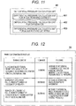
- differential pressure calculation unit 46 will be further described with reference to Fig. 11 .
- Fig. 11 is a schematic diagram illustrating the differential pressure calculation unit of the present embodiment.
- the differential pressure calculation unit 462 related to the oxygenator 2 calculates a differential pressure related to the oxygenator 2 which represents a difference between the standard pressure related to the oxygenator 2 and the actual pressure related to the oxygenator 2. Specifically, the differential pressure calculation unit 462 related to the oxygenator 2 calculates a difference between the standard pressure related to the oxygenator 2 calculated by the standard pressure calculation unit 432 related to the oxygenator 2 and the actual pressure related to the oxygenator 2 calculated by the actual pressure calculation unit 442 related to the oxygenator 2 as the differential pressure related to the oxygenator 2.
- the differential pressure calculation unit 463 related to the blood feeding catheter 6 calculates a differential pressure related to the blood feeding catheter 6 which represents a difference between the standard pressure related to the blood feeding catheter 6 and the actual pressure related to the blood feeding catheter 6. Specifically, the differential pressure calculation unit 463 related to the blood feeding catheter 6 calculates a difference between the standard pressure related to the blood feeding catheter 6 calculated by the standard pressure calculation unit 433 related to the blood feeding catheter 6 and the actual pressure related to the blood feeding catheter 6 calculated by the actual pressure calculation unit 443 related to the blood feeding catheter 6 as the differential pressure related to the blood feeding catheter 6.
- the assumed flow rate storage unit 32 stores the assumed flow rate calculated by the standard flow rate calculation unit 47 and transmitted from the standard flow rate calculation unit 47. Alternatively, the assumed flow rate storage unit 32 stores the assumed flow rate determined by the operator or the like and input by, for example, the touch panel 52.
- the standard information storage unit 33 is given as described above with respect to Figs. 5 to 8 .
- the warning information storage unit 35 stores warning information (warning content) notification of which is provided by the notification processing unit 42.
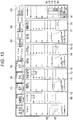
- differential pressure calculation unit 46 will be further described with reference to Fig. 12 .
- Fig. 12 is a schematic diagram illustrating the warning information storage unit of the present embodiment.
- the warning information storage unit 35 stores warning information data that can be assumed by combining a flow rate and a pressure. For example, in a case where the actual flow rate measured by the flow rate measurement unit 24 decreases and the differential pressure related to the blood removing catheter 5 increases, the notification processing unit 42 refers to the warning information stored in the warning information storage unit 35 and displays that there is a suspicion of blood removal failure on the external monitor 16.
- the notification processing unit 42 displays that there is a "possibility of clogging of the blood removing catheter 5" due to the distal end of the blood removing catheter 5 coming into contact with a blood vessel wall or there is a "possibility of a kink of the blood removal tube 11" on the external monitor 16 as the suspicion of the blood removal failure.
- the case where the differential pressure related to the blood removing catheter 5 increases corresponds to, for example, a case where a blood removal pressure (negative pressure) increases.
- the notification processing unit 42 refers to the warning information stored in the warning information storage unit 35 and displays that there is a suspicion of oxygenator failure on the external monitor 16. For example, the notification processing unit 42 displays that there is a "possibility of clogging of the oxygenator 2" due to the life of the oxygenator 2 or the like on the external monitor 16 as the suspicion of oxygenator failure.
- the notification processing unit 42 refers to the warning information stored in the warning information storage unit 35 and displays that there is a suspicion of blood feeding failure on the external monitor 16. For example, the notification processing unit 42 displays that there is a "possibility of clogging of the blood feeding catheter 6" due to a distal end of the blood feeding catheter 6 coming into contact with a blood vessel wall or there is a "possibility of a kink of the blood feeding tube 12" on the external monitor 16 as the suspicion of the blood feeding failure.
- the case where the differential pressure of the blood feeding catheter 6 increases corresponds to, for example, a case where a blood feeding pressure (positive pressure) increases.
- the communication unit 53 communicates with the drive motor 4, the biological monitor 15, the external monitor 16, the pressure measurement unit 20, and the flow rate measurement unit 24, and transmits and receives various types of information and various signals.
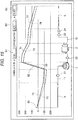
- Fig. 13 is a schematic diagram illustrating an example of the image displayed on the external monitor according to the present embodiment.
- Fig. 14 is a schematic diagram illustrating an example of a relation between arrangements of the circulation circuit and each device of the extracorporeal circulation device according to the present embodiment and a pressure loss.
- the display processing unit 41 of the extracorporeal circulation management device 10 displays an assumed flow rate 66 stored in the assumed flow rate storage unit 32 and an actual flow rate 67 measured by the flow rate measurement unit 24 on the external monitor 16.
- the display processing unit 41 displays standard pressures 71, 74, and 77 calculated by the standard pressure calculation unit 43 and actual pressures 72, 75, and 78 related to the respective devices calculated by the actual pressure calculation unit 44 on the external monitor 16.
- the display processing unit 41 displays a differential flow rate 68, which represents a difference between the assumed flow rate 66 and the actual flow rate 67, and differential pressures 73, 76, and 79 each of which represents a difference between each of the standard pressures 71, 74, and 77 and each of the actual pressures 72, 75, and 78 related to the respective devices on the external monitor 16.
- the display processing unit 41 displays the standard pressure 71 related to the blood removing catheter 5, calculated based on the assumed flow rate 66 by the standard pressure calculation unit 431 related to the blood removing catheter 5, and the actual pressure 72 related to the blood removing catheter 5, calculated by the actual pressure calculation unit 441 related to the blood removing catheter 5 based on the actual pressure measured by the first pressure sensor 21 and the actual flow rate 67 measured by the flow rate measurement unit 24, on the external monitor 16.
- the display processing unit 41 displays the standard pressure 71 related to the blood removing catheter 5 and the actual pressure 72 related to the blood removing catheter 5 in parallel.
- the display processing unit 41 displays the differential pressure 73 related to the blood removing catheter 5 calculated by the differential pressure calculation unit 461 related to the blood removing catheter 5, which represents the difference between the standard pressure 71 related to the blood removing catheter 5 and the actual pressure 72 related to the blood removing catheter 5, on the external monitor 16.
- the display processing unit 41 displays the standard pressure 71 related to the blood removing catheter 5, the actual pressure 72 related to the blood removing catheter 5, and the differential pressure 73 related to the blood removing catheter 5 in parallel.
- the display processing unit 41 displays the standard pressure 74 related to the oxygenator 2, calculated based on the assumed flow rate 66 by the standard pressure calculation unit 432 related to the oxygenator 2, and the actual pressure 75 related to the oxygenator 2, calculated by the actual pressure calculation unit 442 related to the oxygenator 2 based on the actual pressures measured by the second pressure sensor 22 and the third pressure sensor 23 and the actual flow rate 67 measured by the flow rate measurement unit 24, on the external monitor 16.
- the display processing unit 41 displays the standard pressure 74 related to the oxygenator 2 and the actual pressure 75 related to the oxygenator 2 in parallel.
- the display processing unit 41 displays the differential pressure 76 related to the oxygenator 2 calculated by the differential pressure calculation unit 462 related to the oxygenator 2, which represents the difference between the standard pressure 74 related to the oxygenator 2 and the actual pressure 75 related to the oxygenator 2, on the external monitor 16.
- the display processing unit 41 displays the standard pressure 74 related to the oxygenator 2, the actual pressure 75 related to the oxygenator 2, and the differential pressure 76 related to the oxygenator 2 in parallel.
- the display processing unit 41 displays the standard pressure 77 related to the blood feeding catheter 6, calculated based on the assumed flow rate 66 by the standard pressure calculation unit 433 related to the blood feeding catheter 6, and the actual pressure 78 related to the blood feeding catheter 6, calculated by the actual pressure calculation unit 443 related to the blood feeding catheter 6 based on the actual pressure measured by the third pressure sensor 23 and the actual flow rate 67 measured by the flow rate measurement unit 24, on the external monitor 16.
- the display processing unit 41 displays the standard pressure 77 related to the blood feeding catheter 6 and the actual pressure 78 related to the blood feeding catheter 6 in parallel.
- the display processing unit 41 displays the differential pressure 79 related to the blood feeding catheter 6 calculated by the differential pressure calculation unit 463 related to the blood feeding catheter 6, which represents the difference between the standard pressure 77 related to the blood feeding catheter 6 and the actual pressure 78 related to the blood feeding catheter 6, on the external monitor 16.
- the display processing unit 41 displays the standard pressure 77 related to the blood feeding catheter 6, the actual pressure 78 related to the blood feeding catheter 6, and the differential pressure 79 related to the blood feeding catheter 6 in parallel.
- the operator or the like can easily grasp a discrepancy or deviation between the assumed flow rate 66 of blood in the circulation circuit 1R and the actual flow rate 67 of the blood actually flowing in the circulation circuit 1R by confirming the external monitor 16.
- the operator or the like can easily grasp a discrepancy or deviation between each of the standard pressures 71, 74, and 77 calculated based on the assumed flow rate 66 and each of the actual pressures 72, 75, and 78 related to the respective devices (the blood removing catheter 5, the oxygenator 2, and the blood feeding catheter 6) by confirming the external monitor 16.
- the operator or the like can easily grasp the occurrence of the discrepancy or deviation between the assumed flow rate 66 and the actual flow rate 67 and grasp a location of the circulation circuit 1R where the discrepancy or deviation between the standard pressure 71, 74, or 77 and the actual pressure 72, 75, or 78 has occurred and easily grasp that a cause of circulation failure exists near the location by confirming the external monitor 16.
- the location of the circulation circuit 1R where the discrepancy or deviation between the standard pressure 71, 74, or 77 and the actual pressure 72, 75, or 78 has occurred corresponds to a portion where the pressure measurement unit 20 is provided or a portion of each device provided near the pressure measurement unit 20. In this manner, the operator or the like can easily grasp the cause of the circulation failure in the extracorporeal circulation.
- the differential flow rate 68 and the differential pressures 73, 76, and 79 are further displayed on the external monitor 16 as described above.
- the operator or the like can more easily grasp the discrepancy or deviation between the assumed flow rate 66 and the actual flow rate 67 and the discrepancy or deviation between the standard pressure 71, 74, or 77 and the actual pressure 72, 75, or 78 by confirming the external monitor 16.
- the standard pressure 71, 74, or 77 is calculated based on the standard information 331, 332, or 333 stored in the standard information storage unit 33 and the assumed flow rate 66 stored in the assumed flow rate storage unit 32. That is, the standard pressures 71, 74, and 77 change depending on the assumed flow rate 66.
- the extracorporeal circulation device 1 and the extracorporeal circulation management device 10 of the present embodiment can more easily grasp the discrepancy or deviation between the standard pressure 71, 74, or 77 and the actual pressure 72, 75, or 78 by confirming the external monitor 16.
- the standard pressure 71, the actual pressure 72, and the differential pressure 73 related to the blood removing catheter 5, the standard pressure 74, the actual pressure 75, and the differential pressure 76 related to the oxygenator 2, and the standard pressure 77, the actual pressure 78, and the differential pressure 79 related to the blood feeding catheter 6 are displayed in parallel according to the actual arrangement of each device or per actual arrangement of each device.
- the operator or the like can more easily grasp the discrepancy or deviation between the standard pressure 71, 74, or 77 and the actual pressure 72, 75, or 78, and more concretely and easily grasp a location of the circulation circuit 1R where the discrepancy or deviation between the standard pressure 71, 74, or 77 and the actual pressure 72, 75, or 78 has occurred and easily grasp that a cause of circulation failure exists near the location by confirming the external monitor 16 as one display unit.
- the operator or the like can more easily grasp the discrepancy or deviation between the standard pressure 71, 74, or 77 and the actual pressure 72, 75, or 78, and more concretely and easily grasp a location of the circulation circuit 1R where the discrepancy or deviation between the standard pressure 71, 74, or 77 and the actual pressure 72, 75, or 78 has occurred and easily grasp that a cause of circulation failure exists near the location by confirming the external monitor 16 as one display unit.
- a location of the circulation circuit 1R where a discrepancy or deviation between the standard pressure 71, 74, or 77 and the actual pressure 72, 75, or 78 has occurred corresponds to a portion where a pressure sensor detecting an abnormal value among the first pressure sensor 21, the second pressure sensor 22, and the third pressure sensor 23 is provided or a portion of an instrument element provided near the pressure sensor detecting the abnormal value among the blood removing catheter 5, the oxygenator 2, and the blood feeding catheter 6.
- the image (bar graph) displayed on the external monitor 16 changes in real time. As a result, the operator or the like can immediately grasp the discrepancy or deviation between the standard pressure 71, 74, or 77 and the actual pressure 72, 75, or 78.
- the display processing unit 41 displays a French size 61 of the blood removing catheter 5, a type 62 of the oxygenator 2, and a French size 63 of the blood feeding catheter 6 on the external monitor 16.
- the operator or the like can easily change settings of at least any of the French size 61 of the blood removing catheter 5, the type 62 of the oxygenator 2, and the French size 63 of the blood feeding catheter 6 on the image displayed on the external monitor 16.
- the operator or the like can change settings of the standard pressure 71 related to the blood removing catheter 5, the standard pressure 74 related to the oxygenator 2, and the standard pressure 77 related to the blood feeding catheter 6 by changing settings of at least any of the French size 61 of the blood removing catheter 5, the type 62 of the oxygenator 2, and the French size 63 of the blood feeding catheter 6 on the image displayed on the external monitor 16.
- a relation between the French size 61 of the blood removing catheter 5 and the standard pressure 71 related to the blood removing catheter 5 and a relation between the French size 63 of the blood feeding catheter 6 and the standard pressure 77 related to the blood feeding catheter 6 are the same as those described above with respect to Figs. 6 and 8 .
- the display processing unit 41 displays an overall pressure distribution 81 of the extracorporeal circulation device 1 on the external monitor 16.
- the overall pressure distribution 81 of the extracorporeal circulation device 1 includes a head 82 of the centrifugal pump 3, the actual pressure 72 related to the blood removing catheter 5, the actual pressure 75 related to the oxygenator 2, the actual pressure 78 related to the blood feeding catheter 6, and a circuit fixed pressure 84.
- the circuit fixed pressure 84 is a pressure applied to a tube connecting the blood removing catheter 5, the centrifugal pump 3, the oxygenator 2, and the blood feeding catheter 6, and is, for example, a pressure applied to the blood removal tube 11, a pressure applied to the blood feeding tube 12, or the like.
- Fig. 15 is a schematic diagram illustrating another example of the image displayed on the external monitor of the present embodiment.
- the standard pressure 71 related to the blood removing catheter 5, the standard pressure 74 related to the oxygenator 2, the standard pressure 77 related to the blood feeding catheter 6, the actual pressure 72 related to the blood removing catheter 5, the actual pressure 75 related to the oxygenator 2, the actual pressure 78 related to the blood feeding catheter 6, the differential pressure 73 related to the blood removing catheter 5, the differential pressure 76 related to the oxygenator 2, the differential pressure 79 related to the blood feeding catheter 6, and the head 82 of the centrifugal pump 3 are illustrated using bar graphs.
- the image illustrated in Fig. 15 is different from the image illustrated in Fig. 13 .
- the operator or the like can more easily grasp a discrepancy or deviation between the standard pressure 71, 74, or 77 and the actual pressure 72, 75, or 78 while confirming the relation between the arrangements of the circulation circuit 1R and the respective devices of the extracorporeal circulation device 1 and the pressure loss using the external monitor 16.
- the operator or the like can more concretely and easily grasp a location of the circulation circuit 1R where the discrepancy or deviation between the standard pressure 71, 74, or 77 and the actual pressure 72, 75, or 78 has occurred, and easily grasp that a cause of circulation failure exists near the location.
- the image (line graph) displayed on the external monitor 16 changes in real time. As a result, the operator or the like can immediately grasp the discrepancy or deviation between the standard pressure 71, 74, or 77 and the actual pressure 72, 75, or 78.
- the operator or the like can grasp that there is a "possibility of clogging of the blood removing catheter 5" due to the distal end of the blood removing catheter 5 coming into contact with the blood vessel wall or there is a "possibility of a kink of the blood removal tube 11" as a suspicion of blood removal failure.
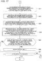
- Figs. 16 and 17 are flowcharts illustrating examples of the control executed by the computer of the extracorporeal circulation management device according to the present embodiment.
- the control unit 40 stores, for example, the assumed flow rate 66, input by the operator or the like in response to the operator's operation or the like on the touch panel 52, in the assumed flow rate storage unit 32.
- the control unit 40 stores the assumed flow rate 66, calculated by the standard flow rate calculation unit 47 using patient information (for example, height, weight, and the like) input by the touch panel 52 in response to the operator's operation on the touch panel 52 and the standard information 334 related to the circulation circuit 1R stored in the standard information storage unit 33, in the assumed flow rate storage unit 32.
- the standard pressure calculation unit 431 related to the blood removing catheter 5 refers to the standard information 331 related to the blood removing catheter 5 stored in the standard information storage unit 33 and calculates the standard pressure 71 related to the blood removing catheter 5 based on the assumed flow rate 66 stored in the assumed flow rate storage unit 32.
- the standard pressure calculation unit 432 related to the oxygenator 2 refers to the standard information 332 related to the oxygenator 2 stored in the standard information storage unit 33 and calculates the standard pressure 74 related to the oxygenator 2 based on the assumed flow rate 66 stored in the assumed flow rate storage unit 32.
- the standard pressure calculation unit 433 related to the blood feeding catheter 6 refers to the standard information 333 related to the blood feeding catheter 6 stored in the standard information storage unit 33 and calculates the standard pressure 77 related to the blood feeding catheter 6 based on the assumed flow rate 66 stored in the assumed flow rate storage unit 32.
- steps S12 to S14 are not particularly limited.
- the processes described above with respect to steps S12 to S14 may be executed at the same time.
- the processes described above with respect to steps S14, S13, and S12 may be executed in this order.
- step S15 the control unit 40 acquires the actual flow rate 67 from the flow rate measurement unit 24 through the communication unit 53.
- the actual pressure calculation unit 441 related to the blood removing catheter 5 acquires an actual pressure (actually measured value) from the first pressure sensor 21 through the communication unit 53, and calculates the actual pressure 72 related to the blood removing catheter 5 based on the actual pressure measured by the first pressure sensor 21 and the actual flow rate 67 acquired from the flow rate measurement unit 24.
- the actual pressure calculation unit 441 related to the blood removing catheter 5 calculates a value, obtained by subtracting a blood pressure (for example, central venous pressure (CVP)) displayed on the biological monitor 15 from an actually measured value measured by the first pressure sensor 21, as a pressure loss that actually occurs in the blood removing catheter 5.
- a blood pressure for example, central venous pressure (CVP)
- CVP central venous pressure
- the actual pressure calculation unit 442 related to the oxygenator 2 acquires an actual pressure (actually measured value) from each of the second pressure sensor 22 and the third pressure sensor 23 through the communication unit 53, and calculates the actual pressure 75 related to the oxygenator 2 based on the actual pressure measured by the second pressure sensor 22, the actual pressure measured by the third pressure sensor 23, and the actual flow rate 67 acquired from the flow rate measurement unit 24. Specifically, the actual pressure calculation unit 442 related to the oxygenator 2 calculates a value, obtained by subtracting an actually measured value measured by the second pressure sensor 22 from an actually measured value measured by the third pressure sensor 23, as a pressure loss that actually occurs in the oxygenator 2.
- the actual pressure calculation unit 443 related to the blood feeding catheter 6 acquires the actual pressure (actually measured value) from the third pressure sensor 23 through the communication unit 53, and calculates the actual pressure 78 related to the blood feeding catheter 6 based on the actual pressure measured by the third pressure sensor 23 and the actual flow rate 67 acquired from the flow rate measurement unit 24. Specifically, the actual pressure calculation unit 443 related to the blood feeding catheter 6 calculates a value, obtained by subtracting the actually measured value measured by the third pressure sensor 23 from a blood pressure (for example, average blood pressure) displayed on the biological monitor 15, as a pressure loss that actually occurs in the blood feeding catheter 6.
- a blood pressure for example, average blood pressure
- step S19 the differential flow rate calculation unit 45 calculates the differential flow rate 68 representing the difference between the assumed flow rate 66 stored in the assumed flow rate storage unit 32 and the actual flow rate 67 acquired from the flow rate measurement unit 24.
- step S21 the differential pressure calculation unit 461 related to the blood removing catheter 5 calculates the differential pressure 73 related to the blood removing catheter 5 representing the difference between the standard pressure 71 related to the blood removing catheter 5 calculated by the process described above with respect to step S12 and the actual pressure 72 related to the blood removing catheter 5 calculated by the process described above with respect to step S16.
- step S22 the differential pressure calculation unit 462 related to the oxygenator 2 calculates the differential pressure 76 related to the oxygenator 2 representing the difference between the standard pressure 74 related to the oxygenator 2 calculated by the process described above with respect to step S13 and the actual pressure 75 related to the oxygenator 2 calculated by the process described above with respect to step S17.
- step S23 the differential pressure calculation unit 463 related to the blood feeding catheter 6 calculates the differential pressure 79 related to the blood feeding catheter 6 representing the difference between the standard pressure 77 related to the blood feeding catheter 6 calculated by the process described above with respect to step S14 and the actual pressure 78 related to the blood feeding catheter 6 calculated by the process described above with respect to step S18.
- step S24 the display processing unit 41 displays all the assumed flow rate 66, the actual flow rate 67, the differential flow rate 68, the standard pressure 71 related to the blood removing catheter 5, the actual pressure 72 related to the blood removing catheter 5, the differential pressure 73 related to the blood removing catheter 5, the standard pressure 74 related to the oxygenator 2, the actual pressure 75 related to the oxygenator 2, the differential pressure 76 related to the oxygenator 2, the standard pressure 77 related to the blood feeding catheter 6, the actual pressure 78 related to the blood feeding catheter 6, and the differential pressure 79 related to the blood feeding catheter 6 simultaneously and in parallel on the external monitor 16 as one display unit.
- step S25 the control unit 40 determines whether or not an absolute value of at least any of the differential flow rate 68, the differential pressure 73 related to the blood removing catheter 5, the differential pressure 76 related to the oxygenator 2, and the differential pressure 79 related to the blood feeding catheter 6 is equal to or larger than a predetermined value.
- the notification processing unit 42 refers to the warning information stored in the warning information storage unit 35, and notifies the external monitor 16 of the warning information.
- the operator or the like can more easily grasp occurrence of a discrepancy or deviation between the assumed flow rate 66 and the actual flow rate 67, and further grasp a location of the circulation circuit 1R where the discrepancy or deviation between the standard pressure 71, 74, or 77 and the actual pressure 72, 75, or 78 has occurred and more easily grasp that a cause of circulation failure exists near the location.
- an example of the warning information notification of which is provided by the notification processing unit 42 is the same as that described above with respect to Fig. 12 .
- step S25: NO the control unit 40 determines in step S27 whether or not the extracorporeal circulation is completed.
- step S27 following step S26, the control unit 40 determines in step S27 whether or not the extracorporeal circulation is completed.
- step S27: NO the processing returns to step S15, and the control unit 40 acquires the actual flow rate 67 from the flow rate measurement unit 24 through the communication unit 53.
- step S27: YES the control unit 40 ends the execution of the program 31 related to the extracorporeal circulation.
- the operator or the like can easily grasp a discrepancy or deviation between the assumed flow rate 66 of blood in the circulation circuit 1R and the actual flow rate 67 of the blood actually flowing in the circulation circuit 1R by confirming the external monitor 16.
- the operator or the like can easily grasp a discrepancy or deviation between each of the standard pressures 71, 74, and 77 calculated based on the assumed flow rate 66 and each of the actual pressures 72, 75, and 78 related to the respective devices (the blood removing catheter 5, the oxygenator 2, and the blood feeding catheter 6) by confirming the external monitor 16.
- the operator or the like can easily grasp the occurrence of the discrepancy or deviation between the assumed flow rate 66 and the actual flow rate 67 and grasp a location of the circulation circuit 1R where the discrepancy or deviation between the standard pressure 71, 74, or 77 and the actual pressure 72, 75, or 78 has occurred and easily grasp that a cause of circulation failure exists near the location by confirming the external monitor 16.
- the location of the circulation circuit 1R where the discrepancy or deviation between the standard pressure 71, 74, or 77 and the actual pressure 72, 75, or 78 has occurred corresponds to a portion where the pressure measurement unit 20 is provided or a portion of each device provided near the pressure measurement unit 20.
- the operator or the like can easily grasp the cause of the circulation failure in the extracorporeal circulation.
- the same effects as those described above can be obtained with respect to Figs. 13 and 14 .
Landscapes
- Health & Medical Sciences (AREA)
- Heart & Thoracic Surgery (AREA)
- Vascular Medicine (AREA)
- Hematology (AREA)
- Animal Behavior & Ethology (AREA)
- Engineering & Computer Science (AREA)
- Anesthesiology (AREA)
- Biomedical Technology (AREA)
- Veterinary Medicine (AREA)
- Life Sciences & Earth Sciences (AREA)
- Public Health (AREA)
- General Health & Medical Sciences (AREA)
- Urology & Nephrology (AREA)
- Cardiology (AREA)
- Emergency Medicine (AREA)
- Physics & Mathematics (AREA)
- Fluid Mechanics (AREA)
- Pulmonology (AREA)
- External Artificial Organs (AREA)
Applications Claiming Priority (2)
| Application Number | Priority Date | Filing Date | Title |
|---|---|---|---|
| JP2018167079 | 2018-09-06 | ||
| PCT/JP2019/033967 WO2020050136A1 (ja) | 2018-09-06 | 2019-08-29 | 体外循環管理装置、体外循環装置および体外循環管理プログラム |
Publications (2)
| Publication Number | Publication Date |
|---|---|
| EP3831421A1 true EP3831421A1 (de) | 2021-06-09 |
| EP3831421A4 EP3831421A4 (de) | 2021-10-06 |
Family
ID=69722282
Family Applications (1)
| Application Number | Title | Priority Date | Filing Date |
|---|---|---|---|
| EP19857408.9A Pending EP3831421A4 (de) | 2018-09-06 | 2019-08-29 | Vorrichtung zur verwaltung der extrakorporalen zirkulation, vorrichtung zur extrakorporalen zirkulation und programm zur verwaltung der extrakorporalen zirkulation |
Country Status (4)
| Country | Link |
|---|---|
| US (1) | US20210178040A1 (de) |
| EP (1) | EP3831421A4 (de) |
| JP (1) | JP7311523B2 (de) |
| WO (1) | WO2020050136A1 (de) |
Families Citing this family (1)
| Publication number | Priority date | Publication date | Assignee | Title |
|---|---|---|---|---|
| CN117750987A (zh) * | 2021-07-30 | 2024-03-22 | 深圳迈瑞生物医疗电子股份有限公司 | 体外循环设备的引导方法和监护设备 |
Family Cites Families (12)
| Publication number | Priority date | Publication date | Assignee | Title |
|---|---|---|---|---|
| EP1322352A4 (de) * | 2000-09-27 | 2010-06-16 | Sorin Group Usa Inc | Wegwerfkartusche fur ein blutperfusionssystem |
| US20030128125A1 (en) * | 2002-01-04 | 2003-07-10 | Burbank Jeffrey H. | Method and apparatus for machine error detection by combining multiple sensor inputs |
| EP2248545B1 (de) * | 2005-08-25 | 2014-03-05 | Gambro Lundia AB | Medizinisches Gerät |
| US8882693B2 (en) * | 2010-12-07 | 2014-11-11 | Zoll Lifebridge Gmbh | Cardiopulmonary apparatus and methods for preserving life |
| EP2581846A1 (de) * | 2011-10-13 | 2013-04-17 | Heartware BVBA | Kardiopulmonales Bypass- oder CPB-Überwachungsinstrument |
| WO2015041150A1 (ja) * | 2013-09-20 | 2015-03-26 | テルモ株式会社 | 表示装置及び表示方法 |
| WO2016035714A1 (ja) * | 2014-09-02 | 2016-03-10 | テルモ株式会社 | 体外循環装置及びその制御方法 |
| EP3231461B1 (de) * | 2014-12-12 | 2019-08-14 | Terumo Kabushiki Kaisha | Extrakorporale kreislaufvorrichtung |
| WO2016096241A1 (en) * | 2014-12-18 | 2016-06-23 | Gambro Lundia Ab | Method of displaying a predicted state, medical apparatus and computer program |
| JP6572059B2 (ja) * | 2015-08-20 | 2019-09-04 | テルモ株式会社 | 体外循環管理装置、体外循環装置及び体外循環管理装置の制御方法 |
| US10272187B2 (en) * | 2017-02-22 | 2019-04-30 | Fresenius Medical Care Holdings, Inc. | System and methods for dialyzer flow rates estimation using measured dialyzer pressures |
| JP2021087461A (ja) * | 2018-03-20 | 2021-06-10 | テルモ株式会社 | 体外循環装置および評価ユニット |
-
2019
- 2019-08-29 EP EP19857408.9A patent/EP3831421A4/de active Pending
- 2019-08-29 JP JP2020541167A patent/JP7311523B2/ja active Active
- 2019-08-29 WO PCT/JP2019/033967 patent/WO2020050136A1/ja not_active Ceased
-
2021
- 2021-03-01 US US17/188,143 patent/US20210178040A1/en active Pending
Also Published As
| Publication number | Publication date |
|---|---|
| WO2020050136A1 (ja) | 2020-03-12 |
| JPWO2020050136A1 (ja) | 2021-08-26 |
| US20210178040A1 (en) | 2021-06-17 |
| JP7311523B2 (ja) | 2023-07-19 |
| EP3831421A4 (de) | 2021-10-06 |
Similar Documents
| Publication | Publication Date | Title |
|---|---|---|
| AU2020372991B2 (en) | Heart-lung machine with augmented reality display | |
| KR101643676B1 (ko) | 의료 기기에 접속된 자체 전원 공급형 장치의 식별 | |
| JP5433634B2 (ja) | 血液浄化装置 | |
| US20250128050A1 (en) | Visual indicator associated with a medical device | |
| Vierecke et al. | Emergency procedures for patients with a continuous flow left ventricular assist device | |
| JP7293355B2 (ja) | 心機能測定システム、体外循環装置および心機能測定プログラム | |
| JP6296815B2 (ja) | 体外循環装置及び体外循環装置の制御方法 | |
| EP3831421A1 (de) | Vorrichtung zur verwaltung der extrakorporalen zirkulation, vorrichtung zur extrakorporalen zirkulation und programm zur verwaltung der extrakorporalen zirkulation | |
| WO2019181610A1 (ja) | 体外循環装置および評価ユニット | |
| JP6572059B2 (ja) | 体外循環管理装置、体外循環装置及び体外循環管理装置の制御方法 | |
| US20240149051A1 (en) | Systems and methods for auxiliary display of hemodynamic signals or indicators | |
| JP7713440B2 (ja) | 体外循環装置 | |
| JP6324797B2 (ja) | 体外循環装置及び体外循環装置の制御方法 | |
| WO2015141622A1 (ja) | 警報装置、体外循環装置及び警報装置の制御方法 | |
| JP5869684B2 (ja) | 生命維持装置のためのコントローラ及びその制御方法 | |
| US20260014305A1 (en) | Extracorporeal circulation device, including management device, and method of operation | |
| US20250128049A1 (en) | Controller for a medical device | |
| US20250276169A1 (en) | Circulatory support devices, systems, and methods | |
| WO2026090518A1 (en) | Systems and methods for determining low pulse pressure events using an auxiliary monitor | |
| JP2024137407A (ja) | 管理装置、管理装置を有する体外循環管理装置、管理装置の作動方法及び管理装置の作動プログラム | |
| JPWO2019181658A1 (ja) | 計測システムおよび計算ユニット | |
| US20250213767A1 (en) | Extracorporeal circulation system, and information processing method | |
| JP2024137408A (ja) | 管理装置、管理装置を有する体外循環管理装置、管理装置の作動方法及び管理装置の作動プログラム | |
| CN121941517A (zh) | 监测体外循环支持的支持脉冲的有效性 |
Legal Events
| Date | Code | Title | Description |
|---|---|---|---|
| STAA | Information on the status of an ep patent application or granted ep patent |
Free format text: STATUS: THE INTERNATIONAL PUBLICATION HAS BEEN MADE |
|
| PUAI | Public reference made under article 153(3) epc to a published international application that has entered the european phase |
Free format text: ORIGINAL CODE: 0009012 |
|
| STAA | Information on the status of an ep patent application or granted ep patent |
Free format text: STATUS: REQUEST FOR EXAMINATION WAS MADE |
|
| 17P | Request for examination filed |
Effective date: 20210302 |
|
| AK | Designated contracting states |
Kind code of ref document: A1 Designated state(s): AL AT BE BG CH CY CZ DE DK EE ES FI FR GB GR HR HU IE IS IT LI LT LU LV MC MK MT NL NO PL PT RO RS SE SI SK SM TR |
|
| REG | Reference to a national code |
Ref country code: DE Ref legal event code: R079 Free format text: PREVIOUS MAIN CLASS: A61M0001140000 Ipc: A61M0001360000 |
|
| A4 | Supplementary search report drawn up and despatched |
Effective date: 20210907 |
|
| RIC1 | Information provided on ipc code assigned before grant |
Ipc: A61M 1/36 20060101AFI20210901BHEP |
|
| DAV | Request for validation of the european patent (deleted) | ||
| DAX | Request for extension of the european patent (deleted) | ||
| STAA | Information on the status of an ep patent application or granted ep patent |
Free format text: STATUS: EXAMINATION IS IN PROGRESS |
|
| 17Q | First examination report despatched |
Effective date: 20240523 |
|
| GRAP | Despatch of communication of intention to grant a patent |
Free format text: ORIGINAL CODE: EPIDOSNIGR1 |
|
| STAA | Information on the status of an ep patent application or granted ep patent |
Free format text: STATUS: GRANT OF PATENT IS INTENDED |
|
| INTG | Intention to grant announced |
Effective date: 20260105 |
|
| RIN1 | Information on inventor provided before grant (corrected) |
Inventor name: HASHIMOTO, TOMOAKI |