EP3831437A1 - Éléments d'ancrage pour un dispositif orientable - Google Patents
Éléments d'ancrage pour un dispositif orientable Download PDFInfo
- Publication number
- EP3831437A1 EP3831437A1 EP19306590.1A EP19306590A EP3831437A1 EP 3831437 A1 EP3831437 A1 EP 3831437A1 EP 19306590 A EP19306590 A EP 19306590A EP 3831437 A1 EP3831437 A1 EP 3831437A1
- Authority
- EP
- European Patent Office
- Prior art keywords
- elongated member
- actuating means
- steerable device
- wire
- flexible
- Prior art date
- Legal status (The legal status is an assumption and is not a legal conclusion. Google has not performed a legal analysis and makes no representation as to the accuracy of the status listed.)
- Granted
Links
Images


Classifications
-
- A—HUMAN NECESSITIES
- A61—MEDICAL OR VETERINARY SCIENCE; HYGIENE
- A61M—DEVICES FOR INTRODUCING MEDIA INTO, OR ONTO, THE BODY; DEVICES FOR TRANSDUCING BODY MEDIA OR FOR TAKING MEDIA FROM THE BODY; DEVICES FOR PRODUCING OR ENDING SLEEP OR STUPOR
- A61M25/00—Catheters; Hollow probes
- A61M25/01—Introducing, guiding, advancing, emplacing or holding catheters
- A61M25/0105—Steering means as part of the catheter or advancing means; Markers for positioning
- A61M25/0133—Tip steering devices
- A61M25/0147—Tip steering devices with movable mechanical means, e.g. pull wires
-
- A—HUMAN NECESSITIES
- A61—MEDICAL OR VETERINARY SCIENCE; HYGIENE
- A61M—DEVICES FOR INTRODUCING MEDIA INTO, OR ONTO, THE BODY; DEVICES FOR TRANSDUCING BODY MEDIA OR FOR TAKING MEDIA FROM THE BODY; DEVICES FOR PRODUCING OR ENDING SLEEP OR STUPOR
- A61M25/00—Catheters; Hollow probes
- A61M25/01—Introducing, guiding, advancing, emplacing or holding catheters
- A61M25/0105—Steering means as part of the catheter or advancing means; Markers for positioning
- A61M25/0133—Tip steering devices
- A61M25/0147—Tip steering devices with movable mechanical means, e.g. pull wires
- A61M2025/015—Details of the distal fixation of the movable mechanical means
-
- A—HUMAN NECESSITIES
- A61—MEDICAL OR VETERINARY SCIENCE; HYGIENE
- A61M—DEVICES FOR INTRODUCING MEDIA INTO, OR ONTO, THE BODY; DEVICES FOR TRANSDUCING BODY MEDIA OR FOR TAKING MEDIA FROM THE BODY; DEVICES FOR PRODUCING OR ENDING SLEEP OR STUPOR
- A61M2205/00—General characteristics of the apparatus
- A61M2205/02—General characteristics of the apparatus characterised by a particular materials
- A61M2205/0266—Shape memory materials
Definitions
- the present invention relates to a steerable device, for instance, such device is used as a guide for a catheter or an endoscope for internally investigating a tubular element such as a pipe, a duct or an artery.
- the device of the invention is particularly suitable for use in the field of surgical investigation inside the body of a subject.
- the device is designed for surgical purpose, it can also be used in other areas needing non-destructive control or diagnostic such as pipeline systems for instance.
- Placement of such devices within pipes is a known technical issue in oil engineering or in motor engineering. Placement of devices within body tubes, such as for example through the ostium (of a vein, an artery, the gastro-intestinal track... etc), is also known in the medical field as being challenging.
- surgeon skill and experience are a major success factor in the complex interventions while recent developments aim at facilitating navigation through complex anatomies as independently as possible from those surgeon skill and experience.
- a flexible elongated device comprising a flexible elongate member with proximal and distal extremities.
- a shape memory element disposed in the flexible elongate member and capable of assuming martensitic and austenitic states and having first and second portions.
- a layer of conductive material formed on at least one of said portions. The layer has a conductivity greater than that of the shape memory element. Electrical current is supplied to the shape memory element.
- the conductive layer serves to conduct current and shunts current flow around that portion of the shape memory element having the layer of conductive material thereon.
- WO2018167300 disclosing a an elongated steerable system for guiding a catheter or an endoscope, comprising: an elongated flexible member comprising, along at least a part of its longitudinal axis, at least one projection which, in transversal section, projects from the elongated flexible member; said at least one projection having a distal end and a proximal end, and defining, in transversal section, two lateral sides projecting from the elongated flexible member; and a wire; wherein said at least one projection comprises at least one transverse retaining and passing means near the distal end of said projection, said retaining and passing means extending transversely to the lateral sides of the projection; and the wire passes through said retaining and passing means alternatively from one lateral side of the projection to the other lateral side of the projection, wherein adherence between the wire and the retaining and passing means retains the wire
- the main objective of the invention is to provide a steerable device comprising actuators and fastening means that are easy to produce, compact and repeatable. According to the invention, the steerable device obtained is flexible enough to allow easy navigation inside a lumen, tube or pipe.
- This invention thus relates to a steerable device configured to be advanced in the lumen of a tubular element, said device comprising:
- the at least one actuating means is made of a shape memory alloy such as NiTi alloy.
- a shape memory alloy such as NiTi alloy.
- Such alloys are used in the invention in surgical domain for their biocompatibility as well as their low density.
- the actuated bending motion is obtained by implementing electrical current that induces a phase transformation in the material through the Joule effect. Once the current no longer flows, the actuating means goes back to initial straight position thanks to the assembly spring back force. The higher the current, the higher the bending angle until a threshold.
- the at least one actuating means comprises a spring or a wire that are more practical, lighter and more compact for a small diameter pipe, lumen or tube.
- the at least one flexible axially elongated member is wire or blade shaped. It may have a cross-section profile under a form selected from star, circular, semicircular, square, rectangular, triangle, pyramidal or any combinations thereof.
- the at least one flexible axially elongated member is spring shaped. More preferably, the spring is a helicoidal spring.
- the at least one flexible axially elongated member is blade shaped so as to improve assembly and to have a preferred common bending plane for the actuators.
- the flexible axially elongated member is wire shaped.
- the fastening means is a ligation around the flexible elongated member. Just like for the actuating means, ligations are easy to implement and reduce the spatial congestion.
- the anti-return means is a glue filled tube, the actuating means going through said tube.
- the actuating means are very solidly anchored while the tube end thickness serves as axial abutments for the fastening means.
- the anti-return means is a crimped tube, the actuating means going through said tube.
- the actuating means are also very solidly anchored while the tube end thickness serves as axial abutments for the fastening means.
- another second anti-return means is made integral with the flexible elongated member so as to maintain the fastening means in place.
- said anti-return means being a recess built into the flexible elongated member and configured to host the at least one fastening means.
- the recess extends in a direction perpendicular to the longitudinal axis of the flexible elongated member.
- the anti-return means is made integral with the actuating means.
- the device according to the invention is easy to produce, compact, and presents a low disassembly risk for the anti-return means
- the at least one anti-return means is a loop encapsulating at least partially the at least one fastening means or said loop being an abutment for the at least one fastening means.
- the loop is obtained by modifying the shape of the actuating means. It is also possible to have a configuration where the at least one anti-return means is a knot, a weld or any local reinforcement located at the at least one actuating means distal end. These configurations add simplicity to the low disassembly risk.
- the at least one anti-return means is a groove built into the actuating means and configured to host the at least one fastening means.
- This configuration adds simplicity to the low disassembly risk.
- the groove extends in a direction perpendicular to the longitudinal axis of the flexible elongated member.
- the groove can be obtained by an indentation process.
- the at least one actuating means is inside an electrically isolating material such as a tube or a coating.
- the material has preferably an electrical and/or temperature isolation effect.
- the at least one actuating means is arranged alongside the external periphery of the elongated member. In this case, the device assembly is made easier.
- the at least one actuating means is arranged alongside the internal periphery of the elongated member.
- the external diameter is constant and the device according to the invention is less bulky.
- the invention has also as an object an assembly method for steerable device according to the invention comprising the steps of:
- the at least one actuating means is arranged alongside the external periphery of the elongated member. In this case, the device assembly is made easier.
- the at least one actuating means is arranged alongside the internal periphery of the elongated member.
- the external diameter is constant and the device obtained according to the method of the invention is less bulky.
- the assembly method according to the invention may be such that the at least one actuating means is a wire, the at least one fastening means is a ligation and the at least one anti-return means is obtained by increasing the contact pressure between the wire and the ligation , with said ligation going alternatively up and under the wire so as to ligate longitudinally partial parts of the wire with the flexible elongated member.
- This method is simple to implement and reduces spatial congestion for the device according to the invention.
- FIGS 1A and 1B one can see an exemplary configuration of the device 1 according to the invention with recesses 5 in the flexible axially elongated member 2 as anti-return means in top and perspective views.
- the flexible axially elongated member 2 is a blade, such blade has been made integral with the anti-return means in the form of two recesses 5.
- a blade is used in this embodiment, but a tubular element is also a possibility for the flexible, axially elongated member.
- the recesses 5 extend transversally towards the axis A1 of the blade 2.
- the actuating means is a flat wire 3 extending longitudinally while being in facial contact with the blade 2. It is thin compared to the ligation 4 diameter.
- Each of the two recesses 5 host ligations 4 as wires winding around said recesses 5 forming coil windings with their axis being the same as the axis A1 of elongation of the blade 2.
- the ligation 4 ties the flat wire 3 and fastens it to the blade 2 thanks to the grooves made in the actuating means 3.
- the combination of the ligation 4, the actuating mean grooves (1B) and potentially the recesses 5 allow to keep the flat wire 3 from sliding when actuated for instance by Joule effect when the flat wire 3 is a shape memory alloy such as NiTi type.
- the recess base of the flexible axially elongated member 2 and the groove base of the actuating means barely coincide radially as depicted in fig 1A .
- FIGS 2A, 2B and 2C one can see an exemplary configuration of the device 1 according to the invention with loops 51 made integral with the wire 30 as anti-return means.
- the flexible axially elongated member 2 is a blade but could have been a tubular element.
- the loop 51 serves as anti-return means. It is in axial abutment contact with the ligation 4 that ties the wire 30 to the blade 2.
- the loop 51 serves as anti-return means.
- the loop 51 serves as anti-return means. It is in axial abutment contact with the ligation 4 that ties the wire 30 to the blade 2 while also encapsulating i.e encompassing said ligation 4 so as to improve the anti-return effect.
- the windings of the ligation 4 are trapped within the close loop 51 made of the wire 30.
- the combination of the ligation 4 that ties the wire 30 to the blade 2 and the close loop 51 keeps the wire 30 from sliding when actuated for instance by Joule effect when the wire 30 is a shape memory alloy such as NiTi type.
- FIGS 3A and 3B one can see an exemplary configuration of the device 1 according to the invention with two knots 52 made integral with the wire 30 as anti-return means.
- the flexible axially elongated member 2 is a blade but could have been a tubular element.
- the knot(s) 52 serve(s) as anti-return means. They are in axial abutment contact with the ligation 4 that ties the wire 30 to the blade 2.
- the anti-return means 57 is a configuration where the wire 30 and the ligation 4 are intertwined (not exactly illustrated for clarity purpose) with the wire 30 going alternatively up and under the windings of the ligation 4 so as to ligate longitudinally partial parts of the wire 30 with the flexible elongated member 2.
- This configuration increases the contact pressure between the actuating means 30 and the ligation 4, thus the adherence between the two latter is increased which is what creates the axial abutment.
- the ligation 4 ties the wire 30 to the blade 2 to keep the wire 30 from sliding when actuated for instance by Joule effect when the wire 30 is a shape memory alloy such as NiTi type.
- the flexible axially elongated member 2 is a blade but could have been a tubular element.
- the three weld seams serve as anti-return means. They are spaced apart longitudinally and in axial abutment contact with the ligation 4 windings that tie the wire 30 to the blade 2.
- the discontinuous weld spots 53 serve as anti-return means. They are in axial abutment contact with the ligation 4 windings that tie the wire 30 to the blade 2.
- the local reinforcement 54 serves as anti-return means, such local reinforcement 54 is axially offset in fig. 5C but could be located in between both ends of the ligation 4.
- the local reinforcement can be the result of a weld or not.
- Said local reinforcement 54 is in axial abutment contact with the ligation 4 windings that tie the wire 30 to the blade 2.
- the ligation 4 ties the wire 30 to the blade 2.
- the combination of the ligation and the anti-return means allows to keep the wire 30 from sliding when actuated for instance by Joule effect when the wire 30 is a shape memory alloy such as NiTi type.
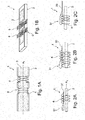
- FIGS 6A, 6B and 6C one can see an exemplary configuration of the device 1 according to the invention with grooves 55 made integral with the wire 30 as anti-return means.
- the flexible axially elongated member 2 is a blade but could have been a tubular element.
- the three grooves serve as anti-return means. They are spaced apart longitudinally and in axial abutment contact with the hosted ligation 4 windings that ties the wire 30 to the blade 2.
- Said grooves can be obtained by different processes such as for example indentation, pressure flattening, or even laser localized fusion.
- Figures 6B and 6C are illustrations of the grooves obtained on the wire with the different methods given as examples.
- the ligation 4 ties the wire 30 to the blade 2.
- the combination of the ligation and the at least one groove allows to keep the wire 30 from sliding when actuated for instance by Joule effect when the wire 30 is a shape memory alloy such as NiTi type.
- Figures 7A and 7B are embodiments, where the anti-return means 56 is tube that is either crimped ( Fig. 7A ) or filled with glue ( Fig. 7B ). In both cases, the tube 56 comprises the wire 30 that goes through said tube 56. The glue or the crimping serves as a blocking element that holds the wire 30 in place.
- the tube 56 has ligation 4 windings on both sides but a configuration with only one ligation 4 winding is possible as long as an axial abutment contact is obtained.
- the combination of the ligation 4 tying the wire 30 to the blade 2 in addition to the crimping or glue effect allows keeping the wire 30 from sliding when actuated for instance by Joule effect when the wire 30 is a shape memory alloy such as NiTi type.
- FIGs 8A and 8B one can see a flexible elongated member in both internal (8A) and external (8B) views.
- an actuating means such as a shape memory alloy (SMA) wire 3 in anchored to the internal surface of the flexible elongated member 2.
- Ligation 4 windings are in axial abutting contact with the knot 5 so as to prevent the SMA wire 3 from sliding once actuated.
- the Fig. 8B is the view from outside showing ligation 4 windings going through recesses for the attachment.
Landscapes
- Health & Medical Sciences (AREA)
- Life Sciences & Earth Sciences (AREA)
- Engineering & Computer Science (AREA)
- Heart & Thoracic Surgery (AREA)
- Animal Behavior & Ethology (AREA)
- Pulmonology (AREA)
- Anesthesiology (AREA)
- Biomedical Technology (AREA)
- Mechanical Engineering (AREA)
- Hematology (AREA)
- Biophysics (AREA)
- General Health & Medical Sciences (AREA)
- Public Health (AREA)
- Veterinary Medicine (AREA)
- Surgical Instruments (AREA)
- Endoscopes (AREA)
- Media Introduction/Drainage Providing Device (AREA)
- Joining Of Building Structures In Genera (AREA)
Priority Applications (8)
| Application Number | Priority Date | Filing Date | Title |
|---|---|---|---|
| EP19306590.1A EP3831437B1 (fr) | 2019-12-06 | 2019-12-06 | Éléments d'ancrage pour un dispositif orientable et procédé de fabrication |
| KR1020227021929A KR20220136344A (ko) | 2019-12-06 | 2020-12-04 | 조종 가능한 장치를 위한 고정 요소 |
| AU2020395912A AU2020395912A1 (en) | 2019-12-06 | 2020-12-04 | Anchoring elements for a steerable device |
| US17/782,006 US20230001149A1 (en) | 2019-12-06 | 2020-12-04 | Anchoring elements for a steerable device |
| CA3163638A CA3163638A1 (fr) | 2019-12-06 | 2020-12-04 | Elements d'ancrage pour un dispositif orientable |
| PCT/EP2020/084725 WO2021110960A1 (fr) | 2019-12-06 | 2020-12-04 | Éléments d'ancrage pour un dispositif orientable |
| JP2022533558A JP7834641B2 (ja) | 2019-12-06 | 2020-12-04 | 操縦可能な機器用の固定要素 |
| ZA2022/07171A ZA202207171B (en) | 2019-12-06 | 2022-06-28 | Anchoring elements for a steerable device |
Applications Claiming Priority (1)
| Application Number | Priority Date | Filing Date | Title |
|---|---|---|---|
| EP19306590.1A EP3831437B1 (fr) | 2019-12-06 | 2019-12-06 | Éléments d'ancrage pour un dispositif orientable et procédé de fabrication |
Publications (3)
| Publication Number | Publication Date |
|---|---|
| EP3831437A1 true EP3831437A1 (fr) | 2021-06-09 |
| EP3831437B1 EP3831437B1 (fr) | 2024-11-20 |
| EP3831437C0 EP3831437C0 (fr) | 2024-11-20 |
Family
ID=69061236
Family Applications (1)
| Application Number | Title | Priority Date | Filing Date |
|---|---|---|---|
| EP19306590.1A Active EP3831437B1 (fr) | 2019-12-06 | 2019-12-06 | Éléments d'ancrage pour un dispositif orientable et procédé de fabrication |
Country Status (8)
| Country | Link |
|---|---|
| US (1) | US20230001149A1 (fr) |
| EP (1) | EP3831437B1 (fr) |
| JP (1) | JP7834641B2 (fr) |
| KR (1) | KR20220136344A (fr) |
| AU (1) | AU2020395912A1 (fr) |
| CA (1) | CA3163638A1 (fr) |
| WO (1) | WO2021110960A1 (fr) |
| ZA (1) | ZA202207171B (fr) |
Families Citing this family (1)
| Publication number | Priority date | Publication date | Assignee | Title |
|---|---|---|---|---|
| EP4405022A4 (fr) * | 2021-09-23 | 2025-08-20 | W Endoluminal Robotics Ltd | Ensemble tubulaire dirigeable pour interventions bronchoscopiques |
Citations (7)
| Publication number | Priority date | Publication date | Assignee | Title |
|---|---|---|---|---|
| US5383852A (en) * | 1992-12-04 | 1995-01-24 | C. R. Bard, Inc. | Catheter with independent proximal and distal control |
| WO1995006494A1 (fr) | 1993-09-03 | 1995-03-09 | Intelliwire, Inc. | Appareil dont la rigidite et le point de courbure sont reglables |
| DE102009037827A1 (de) * | 2009-08-10 | 2011-02-17 | Epflex Feinwerktechnik Gmbh | Medizinisches Katheterinstrument |
| US20120053569A1 (en) * | 2005-06-09 | 2012-03-01 | Greatbatch Ltd. | Push/Pull Wire Anchor |
| US20130281925A1 (en) * | 2012-04-19 | 2013-10-24 | Medtronic Ablation Frontiers Llc | Catheter deflection anchor |
| WO2018167300A1 (fr) | 2017-03-16 | 2018-09-20 | Basecamp Vascular | Structure allongée souple comportant une extrémité orientable |
| US20190329004A1 (en) * | 2016-11-18 | 2019-10-31 | Gsmt Co., Ltd. | Flexible catheter using wires |
Family Cites Families (19)
| Publication number | Priority date | Publication date | Assignee | Title |
|---|---|---|---|---|
| US5480382A (en) * | 1989-01-09 | 1996-01-02 | Pilot Cardiovascular Systems, Inc. | Steerable medical device |
| JPH02206420A (ja) * | 1989-02-06 | 1990-08-16 | Fuji Photo Optical Co Ltd | 内視鏡用アングル装置 |
| US5231989A (en) * | 1991-02-15 | 1993-08-03 | Raychem Corporation | Steerable cannula |
| US5438975A (en) * | 1993-03-24 | 1995-08-08 | Machida Endoscope Co., Ltd. | Distal tip of endoscope having spirally coiled control wires |
| US5562619A (en) * | 1993-08-19 | 1996-10-08 | Boston Scientific Corporation | Deflectable catheter |
| JPH1176403A (ja) * | 1997-07-11 | 1999-03-23 | Olympus Optical Co Ltd | 外科用処置具 |
| US6607496B1 (en) * | 2000-09-12 | 2003-08-19 | Medtronic, Inc. | Steerable stylet with enhanced torsional transfer strength |
| US20020072712A1 (en) * | 2000-10-12 | 2002-06-13 | Nool Jeffrey A. | Medical wire introducer and protective sheath |
| US6511471B2 (en) * | 2000-12-22 | 2003-01-28 | Biocardia, Inc. | Drug delivery catheters that attach to tissue and methods for their use |
| US6790173B2 (en) * | 2002-06-13 | 2004-09-14 | Usgi Medical, Inc. | Shape lockable apparatus and method for advancing an instrument through unsupported anatomy |
| US7037290B2 (en) * | 2002-12-16 | 2006-05-02 | Medtronic, Inc. | Multi-lumen steerable catheter |
| EP2604305A1 (fr) * | 2011-12-16 | 2013-06-19 | VascoMed GmbH | Cathéter et son procédé de fabrication |
| EA027149B1 (ru) * | 2012-08-16 | 2017-06-30 | Кэт Мед Лтд. | Управляемые дефлекторы и способы их использования |
| JP6396788B2 (ja) * | 2014-12-24 | 2018-09-26 | オリンパス株式会社 | 内視鏡装置 |
| JP6712355B2 (ja) * | 2016-07-28 | 2020-06-17 | クック・メディカル・テクノロジーズ・リミテッド・ライアビリティ・カンパニーCook Medical Technologies Llc | 操縦可能なカテーテルにおける遠位側ワイヤ固定 |
| US11235126B2 (en) * | 2017-10-06 | 2022-02-01 | Baylis Medical Company Inc. | Reinforced sheath for a steerable sheath assembly |
| EP3737451A4 (fr) * | 2018-01-11 | 2021-10-20 | The United States Government as Represented by The Department of Veterans Affairs | Cathéter d'échantillonnage à pointe articulée |
| US20250178189A1 (en) * | 2018-04-12 | 2025-06-05 | Basecamp Vascular | Elongated functional system configured to be advanced in the lumen of a pipe, a duct or a tube |
| AU2020408567A1 (en) * | 2019-12-19 | 2022-07-28 | Noah Medical Corporation | Systems and methods for modular endoscope |
-
2019
- 2019-12-06 EP EP19306590.1A patent/EP3831437B1/fr active Active
-
2020
- 2020-12-04 AU AU2020395912A patent/AU2020395912A1/en active Pending
- 2020-12-04 JP JP2022533558A patent/JP7834641B2/ja active Active
- 2020-12-04 KR KR1020227021929A patent/KR20220136344A/ko active Pending
- 2020-12-04 US US17/782,006 patent/US20230001149A1/en active Pending
- 2020-12-04 CA CA3163638A patent/CA3163638A1/fr active Pending
- 2020-12-04 WO PCT/EP2020/084725 patent/WO2021110960A1/fr not_active Ceased
-
2022
- 2022-06-28 ZA ZA2022/07171A patent/ZA202207171B/en unknown
Patent Citations (7)
| Publication number | Priority date | Publication date | Assignee | Title |
|---|---|---|---|---|
| US5383852A (en) * | 1992-12-04 | 1995-01-24 | C. R. Bard, Inc. | Catheter with independent proximal and distal control |
| WO1995006494A1 (fr) | 1993-09-03 | 1995-03-09 | Intelliwire, Inc. | Appareil dont la rigidite et le point de courbure sont reglables |
| US20120053569A1 (en) * | 2005-06-09 | 2012-03-01 | Greatbatch Ltd. | Push/Pull Wire Anchor |
| DE102009037827A1 (de) * | 2009-08-10 | 2011-02-17 | Epflex Feinwerktechnik Gmbh | Medizinisches Katheterinstrument |
| US20130281925A1 (en) * | 2012-04-19 | 2013-10-24 | Medtronic Ablation Frontiers Llc | Catheter deflection anchor |
| US20190329004A1 (en) * | 2016-11-18 | 2019-10-31 | Gsmt Co., Ltd. | Flexible catheter using wires |
| WO2018167300A1 (fr) | 2017-03-16 | 2018-09-20 | Basecamp Vascular | Structure allongée souple comportant une extrémité orientable |
Also Published As
| Publication number | Publication date |
|---|---|
| CA3163638A1 (fr) | 2021-06-10 |
| WO2021110960A1 (fr) | 2021-06-10 |
| ZA202207171B (en) | 2023-11-29 |
| US20230001149A1 (en) | 2023-01-05 |
| JP7834641B2 (ja) | 2026-03-24 |
| AU2020395912A1 (en) | 2022-06-23 |
| KR20220136344A (ko) | 2022-10-07 |
| EP3831437B1 (fr) | 2024-11-20 |
| JP2023504721A (ja) | 2023-02-06 |
| EP3831437C0 (fr) | 2024-11-20 |
Similar Documents
| Publication | Publication Date | Title |
|---|---|---|
| US6585717B1 (en) | Deflection structure | |
| US6533752B1 (en) | Variable shape guide apparatus | |
| JP7043310B2 (ja) | 改善されたループ収縮及びより大きな収縮変位を伴うカテーテル | |
| CN101448540B (zh) | 用于输送医用有效负载的医用输送系统 | |
| US6890329B2 (en) | Defined deflection structure | |
| JP7655934B2 (ja) | 偏向性の遠位端を有する医療機器 | |
| JP2010509026A (ja) | 多次元ループ状先端チップの医療用細長構造体 | |
| US20250178189A1 (en) | Elongated functional system configured to be advanced in the lumen of a pipe, a duct or a tube | |
| JP2024057062A (ja) | パイプ、ダクト、またはチューブの管腔内で前進するように構成された長尺機能システム | |
| EP3831437B1 (fr) | Éléments d'ancrage pour un dispositif orientable et procédé de fabrication | |
| US20210290915A1 (en) | Guide wire | |
| JP7556851B2 (ja) | 操作可能な長尺機能システム | |
| US20070037445A1 (en) | Tubular compliant shape memory alloy actuators | |
| JP5491674B2 (ja) | 方向付け可能端を有する柔軟な細長い構造体の製造方法 | |
| JP2019527088A (ja) | 細長アクチュエータを有する偏向可能なデバイス | |
| EP3595761B1 (fr) | Structure souple allongée présentant une extrémité orientable | |
| EP4653038A1 (fr) | Dispositif orientable allongé à courbure déterminée | |
| US20060247556A1 (en) | Guide wire for use in a surgical procedure | |
| CN121003404A (zh) | 具有确定曲率的细长可转向设备 | |
| IE20040533U1 (en) | A guide wire for use in a surgical procedure |
Legal Events
| Date | Code | Title | Description |
|---|---|---|---|
| PUAI | Public reference made under article 153(3) epc to a published international application that has entered the european phase |
Free format text: ORIGINAL CODE: 0009012 |
|
| STAA | Information on the status of an ep patent application or granted ep patent |
Free format text: STATUS: THE APPLICATION HAS BEEN PUBLISHED |
|
| AK | Designated contracting states |
Kind code of ref document: A1 Designated state(s): AL AT BE BG CH CY CZ DE DK EE ES FI FR GB GR HR HU IE IS IT LI LT LU LV MC MK MT NL NO PL PT RO RS SE SI SK SM TR |
|
| STAA | Information on the status of an ep patent application or granted ep patent |
Free format text: STATUS: REQUEST FOR EXAMINATION WAS MADE |
|
| 17P | Request for examination filed |
Effective date: 20211209 |
|
| RBV | Designated contracting states (corrected) |
Designated state(s): AL AT BE BG CH CY CZ DE DK EE ES FI FR GB GR HR HU IE IS IT LI LT LU LV MC MK MT NL NO PL PT RO RS SE SI SK SM TR |
|
| GRAP | Despatch of communication of intention to grant a patent |
Free format text: ORIGINAL CODE: EPIDOSNIGR1 |
|
| STAA | Information on the status of an ep patent application or granted ep patent |
Free format text: STATUS: GRANT OF PATENT IS INTENDED |
|
| INTG | Intention to grant announced |
Effective date: 20240703 |
|
| RIN1 | Information on inventor provided before grant (corrected) |
Inventor name: MAIANO, CAMILLE Inventor name: CAZENEUVE, JEAN-BAPTISTE |
|
| GRAS | Grant fee paid |
Free format text: ORIGINAL CODE: EPIDOSNIGR3 |
|
| GRAA | (expected) grant |
Free format text: ORIGINAL CODE: 0009210 |
|
| STAA | Information on the status of an ep patent application or granted ep patent |
Free format text: STATUS: THE PATENT HAS BEEN GRANTED |
|
| AK | Designated contracting states |
Kind code of ref document: B1 Designated state(s): AL AT BE BG CH CY CZ DE DK EE ES FI FR GB GR HR HU IE IS IT LI LT LU LV MC MK MT NL NO PL PT RO RS SE SI SK SM TR |
|
| REG | Reference to a national code |
Ref country code: GB Ref legal event code: FG4D |
|
| REG | Reference to a national code |
Ref country code: CH Ref legal event code: EP |
|
| REG | Reference to a national code |
Ref country code: DE Ref legal event code: R096 Ref document number: 602019062174 Country of ref document: DE |
|
| REG | Reference to a national code |
Ref country code: IE Ref legal event code: FG4D |
|
| U01 | Request for unitary effect filed |
Effective date: 20241213 |
|
| U07 | Unitary effect registered |
Designated state(s): AT BE BG DE DK EE FI FR IT LT LU LV MT NL PT RO SE SI Effective date: 20250102 |
|
| U20 | Renewal fee for the european patent with unitary effect paid |
Year of fee payment: 6 Effective date: 20250128 |
|
| PG25 | Lapsed in a contracting state [announced via postgrant information from national office to epo] |
Ref country code: IS Free format text: LAPSE BECAUSE OF FAILURE TO SUBMIT A TRANSLATION OF THE DESCRIPTION OR TO PAY THE FEE WITHIN THE PRESCRIBED TIME-LIMIT Effective date: 20250320 Ref country code: HR Free format text: LAPSE BECAUSE OF FAILURE TO SUBMIT A TRANSLATION OF THE DESCRIPTION OR TO PAY THE FEE WITHIN THE PRESCRIBED TIME-LIMIT Effective date: 20241120 |
|
| PG25 | Lapsed in a contracting state [announced via postgrant information from national office to epo] |
Ref country code: ES Free format text: LAPSE BECAUSE OF FAILURE TO SUBMIT A TRANSLATION OF THE DESCRIPTION OR TO PAY THE FEE WITHIN THE PRESCRIBED TIME-LIMIT Effective date: 20241120 |
|
| PG25 | Lapsed in a contracting state [announced via postgrant information from national office to epo] |
Ref country code: NO Free format text: LAPSE BECAUSE OF FAILURE TO SUBMIT A TRANSLATION OF THE DESCRIPTION OR TO PAY THE FEE WITHIN THE PRESCRIBED TIME-LIMIT Effective date: 20250220 |
|
| PG25 | Lapsed in a contracting state [announced via postgrant information from national office to epo] |
Ref country code: GR Free format text: LAPSE BECAUSE OF FAILURE TO SUBMIT A TRANSLATION OF THE DESCRIPTION OR TO PAY THE FEE WITHIN THE PRESCRIBED TIME-LIMIT Effective date: 20250221 |
|
| PG25 | Lapsed in a contracting state [announced via postgrant information from national office to epo] |
Ref country code: PL Free format text: LAPSE BECAUSE OF FAILURE TO SUBMIT A TRANSLATION OF THE DESCRIPTION OR TO PAY THE FEE WITHIN THE PRESCRIBED TIME-LIMIT Effective date: 20241120 |
|
| PG25 | Lapsed in a contracting state [announced via postgrant information from national office to epo] |
Ref country code: RS Free format text: LAPSE BECAUSE OF FAILURE TO SUBMIT A TRANSLATION OF THE DESCRIPTION OR TO PAY THE FEE WITHIN THE PRESCRIBED TIME-LIMIT Effective date: 20250220 |
|
| PG25 | Lapsed in a contracting state [announced via postgrant information from national office to epo] |
Ref country code: SM Free format text: LAPSE BECAUSE OF FAILURE TO SUBMIT A TRANSLATION OF THE DESCRIPTION OR TO PAY THE FEE WITHIN THE PRESCRIBED TIME-LIMIT Effective date: 20241120 |
|
| PG25 | Lapsed in a contracting state [announced via postgrant information from national office to epo] |
Ref country code: SK Free format text: LAPSE BECAUSE OF FAILURE TO SUBMIT A TRANSLATION OF THE DESCRIPTION OR TO PAY THE FEE WITHIN THE PRESCRIBED TIME-LIMIT Effective date: 20241120 |
|
| PG25 | Lapsed in a contracting state [announced via postgrant information from national office to epo] |
Ref country code: CZ Free format text: LAPSE BECAUSE OF FAILURE TO SUBMIT A TRANSLATION OF THE DESCRIPTION OR TO PAY THE FEE WITHIN THE PRESCRIBED TIME-LIMIT Effective date: 20241120 |
|
| REG | Reference to a national code |
Ref country code: CH Ref legal event code: PL |
|
| PG25 | Lapsed in a contracting state [announced via postgrant information from national office to epo] |
Ref country code: MC Free format text: LAPSE BECAUSE OF FAILURE TO SUBMIT A TRANSLATION OF THE DESCRIPTION OR TO PAY THE FEE WITHIN THE PRESCRIBED TIME-LIMIT Effective date: 20241120 |
|
| PLBE | No opposition filed within time limit |
Free format text: ORIGINAL CODE: 0009261 |
|
| STAA | Information on the status of an ep patent application or granted ep patent |
Free format text: STATUS: NO OPPOSITION FILED WITHIN TIME LIMIT |
|
| PG25 | Lapsed in a contracting state [announced via postgrant information from national office to epo] |
Ref country code: CH Free format text: LAPSE BECAUSE OF NON-PAYMENT OF DUE FEES Effective date: 20241231 |
|
| 26N | No opposition filed |
Effective date: 20250821 |
|
| PG25 | Lapsed in a contracting state [announced via postgrant information from national office to epo] |
Ref country code: IE Free format text: LAPSE BECAUSE OF NON-PAYMENT OF DUE FEES Effective date: 20241206 |
|
| GBPC | Gb: european patent ceased through non-payment of renewal fee |
Effective date: 20250220 |
|
| PG25 | Lapsed in a contracting state [announced via postgrant information from national office to epo] |
Ref country code: GB Free format text: LAPSE BECAUSE OF NON-PAYMENT OF DUE FEES Effective date: 20250220 |
|
| U20 | Renewal fee for the european patent with unitary effect paid |
Year of fee payment: 7 Effective date: 20251230 |
|
| PG25 | Lapsed in a contracting state [announced via postgrant information from national office to epo] |
Ref country code: CY Free format text: LAPSE BECAUSE OF FAILURE TO SUBMIT A TRANSLATION OF THE DESCRIPTION OR TO PAY THE FEE WITHIN THE PRESCRIBED TIME-LIMIT; INVALID AB INITIO Effective date: 20191206 |