EP3831439B1 - Verbindungssystem für komponenten medizinischer vorrichtungen - Google Patents
Verbindungssystem für komponenten medizinischer vorrichtungen Download PDFInfo
- Publication number
- EP3831439B1 EP3831439B1 EP20216112.1A EP20216112A EP3831439B1 EP 3831439 B1 EP3831439 B1 EP 3831439B1 EP 20216112 A EP20216112 A EP 20216112A EP 3831439 B1 EP3831439 B1 EP 3831439B1
- Authority
- EP
- European Patent Office
- Prior art keywords
- vial
- adapter
- membrane
- connection
- connector
- Prior art date
- Legal status (The legal status is an assumption and is not a legal conclusion. Google has not performed a legal analysis and makes no representation as to the accuracy of the status listed.)
- Active
Links
Images


Classifications
-
- A—HUMAN NECESSITIES
- A61—MEDICAL OR VETERINARY SCIENCE; HYGIENE
- A61J—CONTAINERS SPECIALLY ADAPTED FOR MEDICAL OR PHARMACEUTICAL PURPOSES; DEVICES OR METHODS SPECIALLY ADAPTED FOR BRINGING PHARMACEUTICAL PRODUCTS INTO PARTICULAR PHYSICAL OR ADMINISTERING FORMS; DEVICES FOR ADMINISTERING FOOD OR MEDICINES ORALLY; BABY COMFORTERS; DEVICES FOR RECEIVING SPITTLE
- A61J1/00—Containers specially adapted for medical or pharmaceutical purposes
- A61J1/14—Details; Accessories therefor
- A61J1/20—Arrangements for transferring or mixing fluids, e.g. from vial to syringe
- A61J1/2096—Combination of a vial and a syringe for transferring or mixing their contents
-
- A—HUMAN NECESSITIES
- A61—MEDICAL OR VETERINARY SCIENCE; HYGIENE
- A61J—CONTAINERS SPECIALLY ADAPTED FOR MEDICAL OR PHARMACEUTICAL PURPOSES; DEVICES OR METHODS SPECIALLY ADAPTED FOR BRINGING PHARMACEUTICAL PRODUCTS INTO PARTICULAR PHYSICAL OR ADMINISTERING FORMS; DEVICES FOR ADMINISTERING FOOD OR MEDICINES ORALLY; BABY COMFORTERS; DEVICES FOR RECEIVING SPITTLE
- A61J1/00—Containers specially adapted for medical or pharmaceutical purposes
- A61J1/14—Details; Accessories therefor
- A61J1/20—Arrangements for transferring or mixing fluids, e.g. from vial to syringe
- A61J1/2003—Accessories used in combination with means for transfer or mixing of fluids, e.g. for activating fluid flow, separating fluids, filtering fluid or venting
- A61J1/2006—Piercing means
- A61J1/201—Piercing means having one piercing end
-
- A—HUMAN NECESSITIES
- A61—MEDICAL OR VETERINARY SCIENCE; HYGIENE
- A61J—CONTAINERS SPECIALLY ADAPTED FOR MEDICAL OR PHARMACEUTICAL PURPOSES; DEVICES OR METHODS SPECIALLY ADAPTED FOR BRINGING PHARMACEUTICAL PRODUCTS INTO PARTICULAR PHYSICAL OR ADMINISTERING FORMS; DEVICES FOR ADMINISTERING FOOD OR MEDICINES ORALLY; BABY COMFORTERS; DEVICES FOR RECEIVING SPITTLE
- A61J1/00—Containers specially adapted for medical or pharmaceutical purposes
- A61J1/14—Details; Accessories therefor
- A61J1/20—Arrangements for transferring or mixing fluids, e.g. from vial to syringe
- A61J1/2003—Accessories used in combination with means for transfer or mixing of fluids, e.g. for activating fluid flow, separating fluids, filtering fluid or venting
- A61J1/2048—Connecting means
- A61J1/2065—Connecting means having aligning and guiding means
-
- A—HUMAN NECESSITIES
- A61—MEDICAL OR VETERINARY SCIENCE; HYGIENE
- A61J—CONTAINERS SPECIALLY ADAPTED FOR MEDICAL OR PHARMACEUTICAL PURPOSES; DEVICES OR METHODS SPECIALLY ADAPTED FOR BRINGING PHARMACEUTICAL PRODUCTS INTO PARTICULAR PHYSICAL OR ADMINISTERING FORMS; DEVICES FOR ADMINISTERING FOOD OR MEDICINES ORALLY; BABY COMFORTERS; DEVICES FOR RECEIVING SPITTLE
- A61J1/00—Containers specially adapted for medical or pharmaceutical purposes
- A61J1/14—Details; Accessories therefor
- A61J1/20—Arrangements for transferring or mixing fluids, e.g. from vial to syringe
- A61J1/2003—Accessories used in combination with means for transfer or mixing of fluids, e.g. for activating fluid flow, separating fluids, filtering fluid or venting
- A61J1/2079—Filtering means
- A61J1/2082—Filtering means for gas filtration
-
- A—HUMAN NECESSITIES
- A61—MEDICAL OR VETERINARY SCIENCE; HYGIENE
- A61M—DEVICES FOR INTRODUCING MEDIA INTO, OR ONTO, THE BODY; DEVICES FOR TRANSDUCING BODY MEDIA OR FOR TAKING MEDIA FROM THE BODY; DEVICES FOR PRODUCING OR ENDING SLEEP OR STUPOR
- A61M39/00—Tubes, tube connectors, tube couplings, valves, access sites or the like, specially adapted for medical use
- A61M39/10—Tube connectors; Tube couplings
- A61M39/12—Tube connectors; Tube couplings for joining a flexible tube to a rigid attachment
-
- A—HUMAN NECESSITIES
- A61—MEDICAL OR VETERINARY SCIENCE; HYGIENE
- A61M—DEVICES FOR INTRODUCING MEDIA INTO, OR ONTO, THE BODY; DEVICES FOR TRANSDUCING BODY MEDIA OR FOR TAKING MEDIA FROM THE BODY; DEVICES FOR PRODUCING OR ENDING SLEEP OR STUPOR
- A61M39/00—Tubes, tube connectors, tube couplings, valves, access sites or the like, specially adapted for medical use
- A61M39/10—Tube connectors; Tube couplings
- A61M39/14—Tube connectors; Tube couplings for connecting tubes having sealed ends
-
- A—HUMAN NECESSITIES
- A61—MEDICAL OR VETERINARY SCIENCE; HYGIENE
- A61J—CONTAINERS SPECIALLY ADAPTED FOR MEDICAL OR PHARMACEUTICAL PURPOSES; DEVICES OR METHODS SPECIALLY ADAPTED FOR BRINGING PHARMACEUTICAL PRODUCTS INTO PARTICULAR PHYSICAL OR ADMINISTERING FORMS; DEVICES FOR ADMINISTERING FOOD OR MEDICINES ORALLY; BABY COMFORTERS; DEVICES FOR RECEIVING SPITTLE
- A61J1/00—Containers specially adapted for medical or pharmaceutical purposes
- A61J1/14—Details; Accessories therefor
- A61J1/20—Arrangements for transferring or mixing fluids, e.g. from vial to syringe
- A61J1/2003—Accessories used in combination with means for transfer or mixing of fluids, e.g. for activating fluid flow, separating fluids, filtering fluid or venting
- A61J1/2048—Connecting means
- A61J1/2055—Connecting means having gripping means
-
- A—HUMAN NECESSITIES
- A61—MEDICAL OR VETERINARY SCIENCE; HYGIENE
- A61J—CONTAINERS SPECIALLY ADAPTED FOR MEDICAL OR PHARMACEUTICAL PURPOSES; DEVICES OR METHODS SPECIALLY ADAPTED FOR BRINGING PHARMACEUTICAL PRODUCTS INTO PARTICULAR PHYSICAL OR ADMINISTERING FORMS; DEVICES FOR ADMINISTERING FOOD OR MEDICINES ORALLY; BABY COMFORTERS; DEVICES FOR RECEIVING SPITTLE
- A61J1/00—Containers specially adapted for medical or pharmaceutical purposes
- A61J1/14—Details; Accessories therefor
- A61J1/20—Arrangements for transferring or mixing fluids, e.g. from vial to syringe
- A61J1/2003—Accessories used in combination with means for transfer or mixing of fluids, e.g. for activating fluid flow, separating fluids, filtering fluid or venting
- A61J1/2068—Venting means
- A61J1/2072—Venting means for internal venting
-
- A—HUMAN NECESSITIES
- A61—MEDICAL OR VETERINARY SCIENCE; HYGIENE
- A61M—DEVICES FOR INTRODUCING MEDIA INTO, OR ONTO, THE BODY; DEVICES FOR TRANSDUCING BODY MEDIA OR FOR TAKING MEDIA FROM THE BODY; DEVICES FOR PRODUCING OR ENDING SLEEP OR STUPOR
- A61M39/00—Tubes, tube connectors, tube couplings, valves, access sites or the like, specially adapted for medical use
- A61M39/10—Tube connectors; Tube couplings
- A61M2039/1027—Quick-acting type connectors
-
- A—HUMAN NECESSITIES
- A61—MEDICAL OR VETERINARY SCIENCE; HYGIENE
- A61M—DEVICES FOR INTRODUCING MEDIA INTO, OR ONTO, THE BODY; DEVICES FOR TRANSDUCING BODY MEDIA OR FOR TAKING MEDIA FROM THE BODY; DEVICES FOR PRODUCING OR ENDING SLEEP OR STUPOR
- A61M39/00—Tubes, tube connectors, tube couplings, valves, access sites or the like, specially adapted for medical use
- A61M39/10—Tube connectors; Tube couplings
- A61M2039/1044—Verifying the connection, e.g. audible feedback, tactile feedback, visual feedback, using external light sources
-
- A—HUMAN NECESSITIES
- A61—MEDICAL OR VETERINARY SCIENCE; HYGIENE
- A61M—DEVICES FOR INTRODUCING MEDIA INTO, OR ONTO, THE BODY; DEVICES FOR TRANSDUCING BODY MEDIA OR FOR TAKING MEDIA FROM THE BODY; DEVICES FOR PRODUCING OR ENDING SLEEP OR STUPOR
- A61M39/00—Tubes, tube connectors, tube couplings, valves, access sites or the like, specially adapted for medical use
- A61M39/10—Tube connectors; Tube couplings
- A61M2039/1072—Tube connectors; Tube couplings with a septum present in the connector
-
- Y—GENERAL TAGGING OF NEW TECHNOLOGICAL DEVELOPMENTS; GENERAL TAGGING OF CROSS-SECTIONAL TECHNOLOGIES SPANNING OVER SEVERAL SECTIONS OF THE IPC; TECHNICAL SUBJECTS COVERED BY FORMER USPC CROSS-REFERENCE ART COLLECTIONS [XRACs] AND DIGESTS
- Y10—TECHNICAL SUBJECTS COVERED BY FORMER USPC
- Y10T—TECHNICAL SUBJECTS COVERED BY FORMER US CLASSIFICATION
- Y10T29/00—Metal working
- Y10T29/49—Method of mechanical manufacture
- Y10T29/49002—Electrical device making
- Y10T29/49117—Conductor or circuit manufacturing
- Y10T29/49204—Contact or terminal manufacturing
- Y10T29/49208—Contact or terminal manufacturing by assembling plural parts
- Y10T29/49217—Contact or terminal manufacturing by assembling plural parts by elastic joining
Definitions
- the present disclosure relates generally to a connection system. More particularly, the present disclosure relates to a medical connector.
- connection systems for medical device components include a single path for connection and disconnection. Such connection systems involve reverse movements in the same path for connection and disconnection. There is a need for a connection system for medical device components that is intuitive to connect and disconnect while minimizing the risk of inadvertent disconnection.
- US 2010/241088 discloses a system for use and handling a medical liquid that includes a transfer adapter having a port rotatably interconnectable to a male luer fitting of a needleless syringe or infusion tubing line port, and a patient connector having a port rotatable interconnectable to a female luer fitting of an intravascular catheter access port.
- WO 2012/116791 discloses a closure for a syringe or carpule, comprising a main body, and a sealing element which is formed and/or disposed so that it comes into sealing engagement with an opening of a syringe or carpule when the closure is disposed in the closing position thereof and the syringe or carpule.
- the closure is formed as one piece.
- JP 2010/005461 discloses a medicament vial assembly, comprising a storage vial, a stopper member, and fixing rings.
- the stopper member inserted into the opening of the storage vial performs first sealing and the fixing rings holding the stopper member performs the second sealing.
- US 2002/177819 discloses a method and apparatus for injecting medicine from a prefilled container into a patient through an injection needle. After use the needle is automatically shielded. At the end of the injection stroke, the needle is released for retraction, and the spring then retracts the needle to shield the needle.
- the present invention provides a medical connector as claimed in claim 1, including a membrane body having a first end and a second end with a sidewall extending between the first end and the second end, the sidewall of the body defining an annular recess, the second end of the body defining a cavity that extends toward the first end of the body, and the annular recess configured to receive a portion of a medical connector.
- the first end of the body includes a convex surface.
- the cavity of the body may have a first end and terminate at a second end with the second end positioned at least about half a length of the body from the first end of the cavity.
- the second end of the cavity may define a concave surface.
- the cavity may be wider at the first end of the cavity than at the second end of the cavity.
- An annular projection extends from the second end of the body. An inside corner defining the annular recess is radiused.
- the medical connector includes a connector body defining an interior space, and a membrane body having a first end and a second end with a sidewall extending between the first end and the second end of the membrane body.
- the second end of the membrane body defining a cavity that extends toward the first end of the body, where the membrane body is secured to the connector body via an interference fit, and where a portion of the membrane body is received within the interior space of the connector body.
- the sidewall of the membrane body defines an annular recess and the connector body includes a projection extending into the interior space of the connector body, with the projection of the connector body received within the annular recess of the membrane body.
- the sidewall and the annular recess of the membrane body may establish the interference fit with the connector body.
- the first end of the membrane body may extend beyond the connector body.
- the first end of the membrane body includes a convex surface.
- a method of assembling a medical connector includes: providing a connector body defining an interior space; positioning a membrane adjacent to the connector body with the membrane comprising a membrane body having a first end and a second end with a sidewall extending between the first end and the second end of the membrane body, and the second end of the membrane body defining a cavity that extends toward the first end of the body; and inserting a portion of the membrane body within the interior space of the connector body and elastically deforming the membrane body to secure the membrane to the connector body via an interference fit.
- the sidewall of the membrane body defines an annular recess and the connector body may include a projection extending into the interior space of the connector body, with the method further including positioning the projection of the connector body within the annular recess of the membrane body.
- the method may include: positioning an assembly tool on a first end of the connector body adjacent to the interior space, the assembly tool having a conical surface; and elastically deforming the membrane body prior to inserting the portion of the membrane body within the interior space of the connector body by engaging the conical surface of the assembly tool with the portion of the membrane body.
- the present disclosure provides a connection system for connecting a first medical device component to a second medical device component.
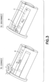
- Fig. 1 illustrates the connection system of the present disclosure connecting the housing of an injector adapter to an intravenous line adapter according to an example not being part of the present disclosure.
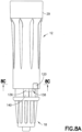
- Fig. 11A illustrates the connection system of the present disclosure connecting the housing of an injector adapter to a vial adapter according to another example not being part of the present disclosure.
- the connection system of the present disclosure may be used to connect other medical device components.
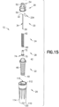
- injector adapter 12 generally includes a cannula 20, a cannula seal 22, a spring 24, a needle hub 26, a cannula stabilizing member 28, a housing 29, a gliding ring 31, a one-way valve 232, and a filter 234.
- cannula 20 includes a distal end 30, a proximal end 32, and a lumen 34 extending therebetween. Distal end 30 is in fluid communication with proximal end 32 via lumen 34 of cannula 20. As shown in Fig.
- distal end 30 of cannula 20 is capable of piercing cannula seal 22 and a vial seal membrane 344 to place a vial chamber 96 in fluid communication with a barrel chamber 176 via cannula 20.
- distal end 30 of cannula 20 defines a sharp point.
- Injector adapter 12 is compatible with a system for the closed transfer of fluids that provides substantially leak-proof sealing and pressure balancing during engagement of a cannula with a vial, during transfer of a substance from a vial chamber to a barrel chamber via the cannula, and during disengagement of the cannula from the vial.
- a leak-proof sealing of the system substantially prevents leakage of both air and liquid during use of the system.
- the system is compatible with a needle and syringe assembly for accessing a medication contained within a vial for administering the medication to a patient.
- the system is also compatible to be used with a drug reconstitution system.
- cannula seal 22 generally includes a self-sealing seal secured over cannula 20 so that cannula seal 22 encloses cannula 20 in a sealed position ( Fig. 25 ) to provide a substantially leak-proof seal preventing any liquid, air, or medication residue from being exposed to a health care provider transferring, reconstituting, transporting, or administering a drug using injector adapter 12.
- Fig. 25 with cannula seal 22 in the sealed position, cannula seal 22 encloses cannula 20 to also prevent accidental needle stick injuries to a user of injector adapter 12.
- Cannula seal 22 includes a distal end 40, a proximal end 42, annular ribbed members 46 extending therebetween, and a shoulder portion 44 ( Fig. 16 ) located on an interior wall 48 near distal end 40 of cannula seal 22.
- distal end 40 of cannula seal 22 includes an annular cavity 41.
- the distal end 40 of cannula seal 22 defines a convex surface and has a transverse cross-sectional shape that is generally circular, although it is contemplated that other shapes and sizes of distal end 40 may be used.
- distal end 40 of cannula seal 22 can have other multi-sided polygon cross-sectional shapes, such as square or oval cross-sectional shapes.
- the cannula seal 22 may have a length that is about equal to a length of the cannula 20 and, upon assembly of the injector adapter 12, the cannula seal 22 may extend about the entire length of the cannula 20.
- cannula seal 22 comprises a resilient material.
- cannula seal 22 is preferably a unitary device molded of any flexible, elastomeric material conventionally used for fabricating gas-proof closures.
- Cannula seal 22 may be formed of a natural rubber material, polyurethane elastomers, butyl rubbers, or similar materials. It is contemplated that cannula seal 22 is formed of a material having a Shore A hardness of approximately 10 to 50.
- cannula seal 22 can have other material hardness values that would provide an appropriate self-sealing material to provide a substantially leak-proof seal with cannula seal 22 in the sealed position, thereby preventing any liquid or medication residue from being exposed to a health care provider transferring, reconstituting, transporting, or administering a drug using injector adapter 12.
- cannula seal 22 comprises a resilient sleeve.
- spring 24 includes a distal end 60 and a proximal end 62.
- Spring 24 provides a biasing force that promotes cannula seal 22 to enclose cannula 20 in the sealed position as will be described in more detail below.
- spring 24 is disposed over cannula 20 such that spring 24 is radially positioned between cannula 20 and cannula seal 22, i.e., cannula seal 22 encloses spring 24 and cannula 20.
- spring 24 is disposed over cannula 20 and within cannula seal 22 such that distal end 60 of spring 24 engages shoulder portion 44 of cannula seal 22. In this manner, spring 24 exerts the biasing force on shoulder portion 44 of cannula seal 22. Shoulder portion 44 of cannula seal 22 also ensures that spring 24 is secured between shoulder portion 44 and needle hub 26.
- needle hub 26 generally includes a distal end 50 and a proximal end 52.
- Proximal end 52 of needle hub 26 includes a barrel connection portion 54.
- barrel connection portion 54 is a female luer connector that is configured to mate with a male luer connector, although other suitable connectors may be utilized.
- the barrel connection portion 54 includes a projection that is configured to be received by a corresponding threaded portion of the male luer connector. Other arrangements for the barrel connection portion 54 may be utilized that deter undesired disconnection from the needle hub 26.
- Needle hub 26 supports and is secured to a portion of cannula 20.
- the needle hub 26 is secured to the cannula 20 via an adhesive, such as an epoxy, although other suitable arrangements for securing the cannula 20 to the needle hub 26 may be utilized.
- Distal end 50 of needle hub 26 also provides a connection with proximal end 62 of spring 24 so that distal end 60 of spring 24 may be compressed relative to proximal end 62 of spring 24 when cannula 20 pierces cannula seal 22 as will be described in more detail below. With spring 24 compressed, spring 24 exerts a biasing force that promotes cannula seal 22 to elastically enclose cannula 20. Referring to Fig.
- spring 24 is loaded between shoulder portion 44 of cannula seal 22 and needle hub 26 in a slightly compressed position so that spring 24 exerts a biasing force that retains cannula seal 22 in the sealed position.
- annular ribbed members 46 of cannula seal 22 provide an additional biasing force that retains cannula seal 22 in the sealed position.
- annular ribbed members 46 of cannula seal 22 and spring 24 are compressed as cannula 20 pierces cannula seal 22 and vial adapter 14. With annular ribbed members 46 of cannula seal 22 compressed, annular ribbed members 46 exert an additional biasing force that promotes cannula seal 22 to elastically enclose cannula 20.
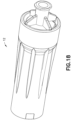
- housing 29 generally includes a distal or first end 110, a proximal or second end 112, and a sidewall 114 extending therebetween.
- Sidewall 114 of housing 29 defines a housing chamber 115.
- Housing chamber 115 is sized and shaped to contain and house the components of injector adapter 12.
- the sidewall 114 of housing 29 includes an exterior wall surface 116 and an interior wall surface 118.
- the interior wall surface 118 of the sidewall 114 includes a connection element 120.
- connection element 120 extends inwardly from interior wall surface 118 of sidewall 114 into housing chamber 115 adjacent distal end 110.
- connection element 120 is engageable with a connection element of a vial adapter or an IV line adapter to secure injector adapter 12 to a vial adapter or an IV line adapter such that significant relative movement between injector adapter 12 and the vial adapter or IV line adapter is prevented.
- connection element 120 comprises a first projecting member 121.
- first projecting member 121 includes an elastically deformable tab for engagement with a connection element of a vial adapter or an IV line adapter as described in more detail below.
- housing 29 also includes an elastically deformable portion for engagement with a connection element of a vial adapter or an IV line adapter as described in more detail below.
- the interior wall surface 118 of the sidewall 114 includes a second connection element 122.
- second connection element 122 extends inwardly from interior wall surface 118 of sidewall 114 into housing chamber 115 adjacent distal end 110.
- Second connection element 122 is spaced a distance from first connection element 120.
- second connection element 122 is spaced approximately 180 degrees (180°) from first connection element 120.
- Second connection element 122 is engageable with a connection element of a vial adapter or an IV line adapter to secure injector adapter 12 to a vial adapter or an IV line adapter.
- second connection element 122 comprises a second projecting member 123.
- second projecting member 123 includes an elastically deformable tab for engagement with a connection element of a vial adapter or an IV line adapter as described in more detail below.
- the first and second connection elements 120, 122 of injector adapter 12 form a first portion of a connection system of the present disclosure which is compatible with connection elements of a vial adapter or an IV line adapter which form a second portion of a connection system of the present disclosure as discussed in more detail below.
- first and second connection elements 120, 122 of injector adapter 12 a material that is capable of elastic flexing without cracking is used to form first and second connection elements 120, 122 of injector adapter 12.
- flexible polymers may be used to form first and second connection elements 120, 122 of injector adapter 12.
- flexible polymers such as polyolefines may be used, e.g., polypropylene, polyethylene, and their co-polymers.
- Housing 29 provides a protective housing which seals the components of injector adapter 12 within housing 29, i.e., housing 29 provides a leak prevention and protection enclosure, protects the components of injector adapter 12 contained within housing 29, and/or maintains a sealed, sterilized environment within housing 29.
- Housing 29 also provides connection elements 120, 122 which provide for engagement with a connection element of a vial adapter or an IV line adapter to secure injector adapter 12 to a vial adapter or an IV line adapter.
- housing 29 also includes an elastically deformable portion for engagement with a connection element of a vial adapter or an IV line adapter as described in more detail below.
- injector adapter 12 includes cannula stabilizing member 28.
- Cannula stabilizing member 28 includes a distal end 70, a proximal end 72, and an annular ring 74 therebetween.
- cannula stabilizing member 28 is disposed within cannula seal 22 such that annular ring 74 of cannula stabilizing member 28 engages shoulder portion 44 of cannula seal 22. In this position, cannula stabilizing member 28 supports a portion of cannula 20 and provides stability to cannula 20 during engagement of cannula 20 with a vial or other device.
- spring 24 is disposed over cannula 20 and within cannula seal 22 such that distal end 60 of spring 24 engages annular ring 74 of cannula stabilizing member 28. In this manner, spring 24 exerts the biasing force on annular ring 74 of cannula stabilizing member 28 which exerts the biasing force on shoulder portion 44 of cannula seal 22.
- injector adapter 12 includes gliding ring 31.
- Gliding ring 31 includes an exterior wall surface, i.e., a gliding surface 252 and an interior surface 254.
- the interior surface 254 of gliding ring 31 includes an annular protrusion 256.
- the annular protrusion 256 extends radially inwards from interior surface 254.
- gliding ring 31 is disposed within housing 29 such that annular protrusion 256 is received within annular cavity 41 of cannula seal 22 to secure the gliding ring 31 to the cannula seal 22 such that the gliding ring 31 is positioned between cannula seal 22 and interior wall surface 118 of housing 29.
- gliding ring 31 supports a portion of cannula seal 22 and provides stability to cannula seal 22 within housing 29 during engagement of cannula 20 with a vial or other device.
- Gliding ring 31 also provides stability to cannula seal 22 with cannula seal 22 moving within housing 29.
- injector adapter 12 is configured to provide an aspiration arrangement 230 to allow air to enter the injector adapter 12 for aspirating air into a syringe barrel while using seal and pressure equalization system 10.
- the aspiration arrangement 230 allows a user to aspirate air into the barrel chamber 176 after injector adapter 12 is secured to the barrel assembly 16.
- the aspiration arrangement 230 includes a one-way valve 232 and filter 234.
- the needle hub 26 includes an inner wall 236 and an outer wall 238 that defines an annular recess 240.
- the needle hub 26 further defines at least one passageway 242 that extends perpendicularly to a longitudinal axis of the hub 26.
- the passageway 242 extends through the inner wall 236.
- the outer wall 238 defines a cutout 243 that is configured to receive the filter 234.
- the cutout 243 is in fluid communication with the passageway 242 and the annular recess 240.
- the filter 234 is a flat filter sheet positioned within the cutout 243, although other suitable arrangements may be utilized.
- the filter 234 may be ring-shaped and fitted within the annular recess 240 rather than being positioned within the cutout 243.
- the filter 234 may be any suitable commercially available filter, such as a particulate air filter having a pore size of 0.2 ⁇ m or larger.
- the filter 234 may be configured remove viable micro-organisms.
- the one-way valve 232 is embodied as an extension 244 of the cannula seal 22 that extends into the needle hub 26.
- the extension 244 is formed integrally with the cannula seal 22, although the extension 244 may be formed separately.
- the extension 244 of the cannula seal 22 abuts and extends along at least a portion of an inner surface 246 of the inner wall 236.
- the extension 244 is configured to selectively allow the flow of outside air through the passageway 242 and the filter 234 and into the cannula seal 22.
- the extension 244 in response to a pressure drop within the cannula seal 22 caused by aspiration, the extension 244 will deflect inwardly to open the passageway 242 and allow outside air to be drawn into the barrel chamber 176 of barrel assembly 16. After aspiration, the extension 244 will return to its original position to block or close the passageways 242. When the cannula seal 22 is under a positive pressure, the extension 244 is forced radially outward and continues to block and seal the passageway 242. Air may first be injected into the vial chamber 96 of vial 90 prior to withdrawing fluid, such as substance 98, from the vial chamber 96.
- fluid such as substance 98
- the one-way valve 232 and filter 234 allows a user to aspirate air into the barrel chamber 176 after the injector adapter 12 is secured to the barrel assembly 16. Furthermore, the filter 234 is configured to filter the outside air that is aspirated into the barrel assembly 16, which advantageously allows clean filter air to be injected into the vial chamber 96.
- proximal end 52 of needle hub 26 is attached to a barrel 160 of barrel assembly 16.
- needle hub 26 With needle hub 26 supporting a portion of cannula 20 and with proximal end 52 of needle hub 26 attached to barrel 160 of barrel assembly 16, needle hub 26 attaches cannula 20 to barrel assembly 16 such that cannula 20 is in fluid communication with barrel chamber 176 of barrel 160.
- barrel assembly 16 includes barrel 160, a plunger rod 162, and a stopper 164.
- Barrel assembly 16 may be adapted for the dispensing and delivery of a fluid and/or collection of a fluid.
- barrel assembly 16 may be used for injection or infusion of fluid such as a medication into a patient.
- Barrel assembly 16 is contemplated for use in connection with a needle, such as by connecting barrel assembly 16 to cannula 20 as described, connecting barrel assembly 16 to a separate needle assembly (not shown), or alternatively, for connection with an intravenous (IV) connection assembly such as IV line adapter 18.
- IV intravenous
- syringe assembly including, but not limited to, metered dose syringes, aspiration syringes for withdrawing fluid from a patient or medication from a container or vial, and the like.
- IV line adapter 18 includes first end 130 and opposing second end 131. IV line adapter 18 provides a compact and accessible connector for connecting a cartridge or barrel containing a reconstituted drug to an intravenous line or an injection apparatus for administering the drug to a patient.
- First end 130 of IV line adapter 18 includes a connection system 132.
- Connection system 132 of IV line adapter 18 forms a portion of a connection system of the present disclosure which is compatible with a connection system 120, 122 of injector adapter 12 which form another portion of a connection system of the present disclosure as discussed in more detail below.
- connection system 132 includes a first connection element 133 disposed at first end 130 of IV line adapter 18 which is engageable with a connection element 120, 122 of an injector adapter 12 to secure the injector adapter 12 to IV line adapter 18.
- first end 130 of IV line adapter 18 includes a second connection element 134.
- Second connection element 134 is spaced a distance from first connection element 133.
- second connection element 134 is spaced approximately 180 degrees (180°) from first connection element 133.
- Second connection element 134 is engageable with a connection element 120, 122 of an injector adapter 12 to secure the injector adapter 12 to IV line adapter 18 such that significant relative movement between injector adapter 12 and IV line adapter 18 is prevented.
- first connection element 133 of connection system 132 includes a first connection path 136, a first disconnection path 138, and a first securement element 140 disposed between the first connection path 136 and first disconnection path 138.
- first connection path 136, first disconnection path 138, and first securement element 140 together generally define a U-shaped path.
- First connection path 136 is distinct from first disconnection path 138. In this manner, the distinct connection and disconnection paths allow for the fine tuning of tactile and audible responses separately for connection and disconnection movements.
- divider wall 139 is disposed between first connection path 136 and first disconnection path 138.
- first connection element 133 of IV line adapter 18 may be used for first connection element 133 of IV line adapter 18.
- first connection element 133 of IV line adapter 18 is made from a rigid material such as a hard plastic, metal, or ceramic material. The important characteristics of the materials used to make first connection element 133 of IV line adapter 18 is that they are a more rigid material than the materials used to form connection element 120 of injector adapter 12.
- first connection path 136 comprises a first connection channel.
- first disconnection path 138 comprises a first disconnection channel.
- first securement element 140 comprises a locking recess.
- First connection path 136 includes a connection guide surface 141, a first connection guide wall 142, and a second connection guide wall 143 which together form a channel that guides connection element 120 of injector adapter 12 to enter engagement with IV line adapter 18 as described in more detail below.
- Connection guide surface 141 includes an entry portion 144 and an exit portion 145 adjacent securement element 140.
- guide surface 141 tapers upwards from entry portion 144 to exit portion 145. In this manner, guide surface 141 receives, guides, and deforms connection element 120 of injector adapter 12 as described in more detail below.
- First connection path 136 includes a step member 135 disposed between first securement element 140 and first disconnection path 138.
- Step member 135 includes an exit recess step 147, an enter disconnection path step 148, and a top step surface 149 disposed therebetween.
- Step member 135 provides a component that allows connection element 120 of injector adapter to be rotated out from engagement with securement element 140. Also, step member 135 can be used to tune resistance and provide tactile feel during a disconnection movement as described in more detail below.
- First disconnection path 138 includes a disconnection guide surface 150, a first disconnection guide wall 151, and a second disconnection guide wall 152 which together form a channel that guides connection element 120 of injector adapter 12 to exit IV line adapter 18 as described in more detail below.
- Disconnection guide surface 150 includes an entry portion 153 adjacent step member 135 and an exit portion 154 that includes a barrier exit wall 155.
- guide surface 150 tapers upwards from entry portion 153 to exit portion 154. In this manner, guide surface 150 receives, guides, and deforms connection element 120 of injector adapter 12 as described in more detail below.
- second connection element 134 of connection system 132 includes a second connection path 170, a second disconnection path 171, and a second securement element 172 disposed between the second connection path 170 and second disconnection path 171.
- second connection path 170, second disconnection path 171, and second securement element 172 together generally define a U-shaped path.
- Second connection path 170 is distinct from second disconnection path 171. In this manner, the distinct connection and disconnection paths allow for the fine tuning of tactile and audible responses separately for connection and disconnection movements.
- divider wall 174 is disposed between second connection path 170 and second disconnection path 171.
- second connection element 134 of IV line adapter 18 may be used for second connection element 134 of IV line adapter 18.
- a wide variety of thermoplastic and thermosetting polymers and similar materials may be used to form second connection element 134 of IV line adapter 18.
- second connection element 134 of IV line adapter 18 is made from a rigid material such as a hard plastic, metal, or ceramic material. The important characteristics of the materials used to make second connection element 134 of IV line adapter 18 is that they are a more rigid material than the materials used to form second connection element 122 of injector adapter 12.
- second connection path 170 comprises a second connection channel.
- second disconnection path 171 comprises a second disconnection channel.
- second securement element 172 comprises a locking recess.
- Second connection path 170 includes a connection guide surface 180, a first connection guide wall 181, and a second connection guide wall 182 which together form a channel that guides second connection element 122 of injector adapter 12 to enter engagement with IV line adapter 18 as described in more detail below.
- Connection guide surface 180 includes an entry portion 183 and an exit portion 184 adjacent securement element 172.
- guide surface 180 tapers upwards from entry portion 183 to exit portion 184. In this manner, guide surface 180 receives, guides, and deforms second connection element 122 of injector adapter 12 as described in more detail below.
- Second connection path 170 includes a step member 173 disposed between second securement element 172 and second disconnection path 171.
- Step member 173 includes an exit recess step 191, an enter disconnection path step 192, and a top step surface 193 disposed therebetween.
- Step member 173 provides a component that allows second connection element 122 of injector adapter 12 to be rotated out from engagement with securement element 172. Also, step member 173 can be used to tune resistance and provide tactile feel during a disconnection movement as described in more detail below.
- Second disconnection path 171 includes a disconnection guide surface 185, a first disconnection guide wall 186, and a second disconnection guide wall 187 which together form a channel that guides second connection element 122 of injector adapter 12 to exit IV line adapter 18 as described in more detail below.
- Disconnection guide surface 185 includes an entry portion 188 adjacent step member 173 and an exit portion 189 that includes a barrier exit wall 190.
- guide surface 185 tapers upwards from entry portion 188 to exit portion 189. In this manner, guide surface 185 receives, guides, and deforms second connection element 122 of injector adapter 12 as described in more detail below.
- First end 130 of IV line adapter 18 includes a pierceable barrier membrane 158.
- the pierceable barrier membrane 158 provides for a liquid and gas tight seal between a piercing member of a barrel assembly and the pierceable barrier membrane 158 during fluid transfer of a medication to a patient so to minimize leakage and thereby prevent exposure of hazardous medicaments to a user.
- Barrier membrane 158 provides a self-sealing seal that, with a barrel assembly attached to IV line adapter 18, provides a leak-proof seal preventing any substance being administered to a patient from being exposed to a health care provider administering the medication.
- barrier membrane 158 comprises a resilient material.
- barrier membrane 158 is preferably a unitary device molded of any flexible, elastomeric material conventionally used for fabricating gas-proof closures.
- Barrier membrane 158 may be formed of a natural rubber material, polyurethane elastomers, butyl rubbers, or similar materials.
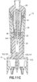
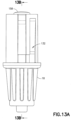
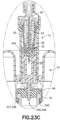
- vial adapter 14 includes a vial access system 312 and a pressure equalization system 314.
- Vial adapter 14 is configured to establish fluid communication between a first container and a second container.
- vial adapter 14 is attachable to a vial 90.
- vial 90 may be a standard drug vial of any type having an open head portion 93 covered by a pierceable septum 94 of an elastomeric material. Walls 95 of vial 90 define vial chamber 96 for containing a substance 98. Vial septum 94 is engaged with head portion 93 of vial 90 to seal the substance 98 within vial chamber 96.
- Vial adapter 14 is compatible with a system for the closed transfer of fluids that provides substantially leak-proof sealing and pressure balancing during engagement of a cannula with a vial, during transfer of a substance from a vial chamber to a barrel chamber via the cannula, and during disengagement of the cannula from the vial.
- vial adapter 14 With pressure equalization system 314 secured to vial access system 312, vial adapter 14 includes first end 302, opposing second end 303, and wall 304 extending between first end 302 and second end 303. Wall 304 defines an exterior profile 306 as will be described in more detail below.
- vial adapter 14 With vial adapter 14 attached to a vial 90, the vial adapter 14 provides a leak-proof seal and pressure equalization system that prevents any substance contained within a chamber of the vial from being exposed to a health care provider reconstituting, transporting, or administering a drug.
- vial adapter 14 and the packaging member provides a secure fit therebetween, such that, with vial adapter 14 received within the packaging member, the packaging member can be used as an interface between the hand of a user and vial adapter 14 so that vial adapter 14 can be placed onto a vial without taking vial adapter 14 out of the packaging member.
- vial access system 312 of vial adapter 14 includes vial access housing 330 having first end 332 and opposing second end 334.
- First end 332 of vial access housing 330 includes a connection element or connection system 336.
- First connection element 336 is engageable with a connection element 120, 122 of an injector adapter 12 to secure the injector adapter 12 to vial adapter 14.
- first end 332 of vial access housing 330 includes a second connection element or second connection system 339.
- Second connection element 339 is spaced a distance from first connection element 336.
- second connection element 339 is spaced approximately 180 degrees (180°) from first connection element 336.
- Second connection element 339 is engageable with a connection element 120, 122 of an injector adapter 12 to secure the injector adapter 12 to vial adapter 14 such that significant relative movement between injector adapter 12 and vial adapter 14 is prevented.
- first and second connection elements 336, 339 of vial adapter 14 form a second portion of a connection system of the present disclosure which is compatible with connection elements of an injector adapter which form a first portion of a connection system of the present disclosure as discussed in more detail below.
- Figs. 19A-19G illustrate another exemplary example of the present disclosure.
- the connection system of first and second connection elements 336, 339 of vial adapter 14 illustrated in Figs. 19A-19G include similar components to the connection system of first connection element 133 and second connection element 134 of IV line adapter 18 illustrated in Figs. 12-14B , and the similar components are denoted by a reference number followed by the letter A.
- these similar components and the similar steps of using the connection system of first and second connection elements 336, 339 of vial adapter 14 will not all be discussed in conjunction with the example illustrated in Figs. 19A-19G .
- First end 332 of vial access housing 330 is substantially formed by a neck portion 333.
- neck portion 333 may include a guiding groove arranged therein to guide corresponding guiding protrusions on a cannula adapter or syringe assembly, for example, to establish a secure attachment between the cannula adapter or syringe assembly and vial adapter 14 after which fluid communication can be established.
- a vial connection member or vial engagement member 337 is disposed at second end 334 of vial access housing 330.
- vial connection member 337 includes a plurality of vial grip members 338 that are disposed at second end 334 of vial access housing 330.
- Vial grip members 338 are attachable to a vial 90 to secure vial adapter 14 to the vial 90.
- Each vial grip member 338 includes a hook protrusion 340 arranged to engage a corresponding flange on a container such as a vial 90 as shown in Figs. 20A and 20B .
- Vial connection member 337 of vial access housing 330 may be dimensioned to be attached to containers of any size and volume.
- vial connection member 337 of vial access housing 330 may include other connection mechanisms for securing vial adapter 14 to vial 90 such as a threaded portion, a snap fit mechanism, locking tabs, or other similar mechanism.
- a fluid transfer channel 342 extends substantially between first end 332 and second end 334 of vial access housing 330.
- the purpose of fluid transfer channel 342 is to permit a needle cannula to extend through vial access housing 330 of vial adapter 14 and to thereby permit fluid to be transferred through vial adapter 14.
- a pierceable barrier member or vial seal membrane 344 is arranged in the fluid transfer channel 342 at first end 332 of vial access housing 330.
- the pierceable barrier member 344 provides for a liquid and gas tight seal between a piercing member and the pierceable barrier member 344 during fluid transfer so to minimize leakage and thereby prevent exposure of hazardous medicaments to a user.
- Vial seal membrane 344 provides a self-sealing seal that, with vial adapter 14 attached to vial 90 such that vial seal membrane 344 is aligned with vial septum 94, provides a leak-proof seal preventing any substance contained within vial chamber 96 from being exposed to a health care provider reconstituting, transporting, or administering a drug using system 10.
- vial seal membrane 344, vial sleeve seal 350, and cannula seal 22 provide a leak-proof seal that is liquid tight and airtight preventing any substance residue from being exposed to a health care provider while reconstituting or withdrawing substance 98 from vial 90 to barrel 160 via cannula 20.
- vial seal membrane 344 comprises a resilient material.
- vial seal membrane 344 is preferably a unitary device molded of any flexible, elastomeric material conventionally used for fabricating gas-proof closures.
- Vial seal membrane 344 may be formed of a natural rubber material, polyurethane elastomers, butyl rubbers, or similar materials. It is contemplated that vial seal membrane 344 is formed of a material having a Shore A hardness of approximately 10 to 50.
- vial seal membrane 344 can have other material hardness values that would provide an appropriate self-sealing material to provide a leak-proof seal with vial septum 94 of vial 90 and cannula seal 22, thereby preventing any liquid or medication residue from being exposed to a health care provider reconstituting, transporting, or administering a drug using system 10.
- a piercing member or spike member 346 Protruding out from vial access housing 330 at second end 334 is a piercing member or spike member 346 which includes piercing tip 348.
- fluid transfer channel 342 extends inside of spike member 346.
- the spike member 346 extends in a direction substantially parallel with the plurality of vial grip members 338 and serves the purpose of piercing a fluid container such as a vial 90 during assembly of vial adapter 14 to a vial 90 as is shown in greater detail in Fig. 20B .
- a vial sleeve seal 350 is disposed over the spike member 346.
- the vial sleeve seal 350 provides a seal between vial adapter 14 and a vial 90 with the piercing tip 348 of spike member 346 engaged with the vial 90.
- vial sleeve seal 350 comprises a rubber spike sleeve.
- pressure equalization system 314 includes pressure equalization housing 360 and toroidal expandable balloon 362 which includes an expansion chamber 366.
- Pressure equalization housing 360 defines a tapered exterior wall portion 361 and an interior annular ring cavity portion 363.
- tapered exterior wall portion 361 includes a plurality of stabilizing ribs 365.
- stabilizing ribs 365 may extend in an axial direction along tapered exterior wall portion 361 of pressure equalization housing 360 and the ribs 365 may be spaced around a periphery of pressure equalization housing 360.
- Expandable balloon 362 includes a variable volume.
- Pressure equalization housing 360 comprises a relatively rigid material and expandable balloon 362 comprises a relatively flexible material.
- expandable balloon 362 comprises a thin, transparent plastic film that is attached to pressure equalization housing 360 in a gastight manner.
- expandable balloon 362 is designed as a bellow which is compressible and extendable and thus the volume of the expansion chamber 366 of expandable balloon 362 can thereby be increased and decreased.
- interior annular ring cavity portion 363 of pressure equalization housing 360 extends radially around vial access housing 330 and expandable balloon 362 extends radially around vial access housing 330.
- Pressure equalization housing 360 provides a barrier wall member that protects expandable balloon 362 from being torn during engagement of a cannula with a vial, during transfer of a substance from a vial chamber to a barrel chamber via the cannula, and during disengagement of the cannula from the vial.
- the vial adapter 14 is balanced such that a center of mass is positioned at about a longitudinal axis of vial adapter 14.
- expandable balloon 362 extends 360 degrees (360°) radially around vial access housing 330.
- a portion of toroidal expandable balloon 362 is not covered by pressure equalization housing 60. In this manner, expandable balloon 362 is capable of expanding in an axial direction.
- pressure equalization housing 360 and vial access housing 330 are a single integral component. In another example, pressure equalization housing 360 and vial access housing 330 are separate components and pressure equalization housing 360 is attachable to vial access housing 330 such that significant relative movement between pressure equalization housing 360 and vial access housing 330 is prevented.
- a pressure normalization channel 370 extends from second end 334 of vial access housing 330 to exit aperture 364 of pressure equalization housing 360.
- Pressure normalization channel 370 is arranged to provide gas communication between the expandable balloon 362 and the interior of a vial 90 when the vial adapter 14 is connected to a vial 90.
- a syringe or cannula assembly may be used to inject fluid into the vial 90 or to withdraw fluid therefrom as described in more detail below.
- pressure normalization channel 370 extends from a portion of piercing tip 348 of spike member 346 and substantially parallel with fluid transfer channel 342 inside spike member 346.
- the pressure normalization channel 370 diverts in a direction perpendicular to fluid transfer channel 342 substantially at shoulder portion 372 of pressure normalization channel 370.
- the pressure normalization channel 370 includes an inlet opening 374 arranged substantially at a portion of piercing tip 348 of spike member 346 and an outlet opening 376 positioned substantially at exit aperture 364 of pressure equalization housing 360.
- the pressure normalization channel 370 comprises a filter 380 arranged to cover a region of the pressure normalization channel 370.
- the filter 380 serves the purpose of preventing any fluid from a container, such as a vial, from reaching expansion chamber 366 of expandable balloon 362.
- the filter 380 is preferably a hydrophobic filter which permits gas to pass, but prevents liquid to pass.
- the filter 380 may be secured within pressure equalization housing 360 via filter holder 382.
- vial adapter 14 may also include a valve arrangement positioned in the proximity of outlet opening 376 of the pressure normalization channel 370.
- a valve arrangement prevents clogging of the filter 380 by providing a cracking pressure to the valve arrangement for the fluid which flows in a direction from the inlet opening 374 to the outlet opening 376 of the pressure normalization channel 370 while permitting preferably a minimal cracking pressure in the opposite direction.
- vial adapter 14 When preparing and administering drugs, care has be taken to minimize, or preferably eliminate, the risk of exposing people, such as medical and pharmacological personnel, to toxic substances. Some drugs must be dissolved or diluted before they are administered, which involves transferring a solvent from one container to a sealed vial containing the drug in powder or liquid form, by means of a needle, for example. Drugs may be inadvertently released into the atmosphere in gas form or by way of aerosolization, during the withdrawal of the needle from the vial, and while the needle is inside the vial, if any pressure differential between the interior of the vial and surrounding atmosphere exists.
- Vial adapter 14 of the present disclosure eliminates this problem by using pressure equalization system 314 of vial adapter 14 that may be attached to a vial during the preparation of drugs.
- the pressure equalization system 314 includes an expandable balloon 362 which in communication with the interior of the vial 90 ensures that neither an increased pressure nor a vacuum can occur inside the vial 90 when gas or liquid is injected into or withdrawn from the vial 90.
- the expandable balloon 362 may be filled with cleaned or sterilized air prior to its use to ensure that the contents of the vial 90 do not become contaminated with air-borne particles such as dust, pollen, mold or bacteria, or other undesirable substances.
- the vial adapter 14 is assembled via its connection element 336 of vial access housing 330 to a cannula 20 of injector adapter 12 which in turn can be connected to a fluid container, such as barrel assembly 16, and the vial adapter 14 is also assembled via its vial connection members 337 with a second fluid container, such as a vial 90.
- a vial 90 As vial adapter 14 is assembled with the vial 90, the piercing tip 348 of the spike member 346 is pierced through a septum 94 of the vial 90.
- Vial 90 may be a standard drug vial of any type having an open head portion covered by a pierceable septum of an elastomeric material.
- the walls 95 of vial 90 define a vial chamber 96 for containing a substance 98.
- the vial septum 94 is engaged with the head portion 93 of vial 90 to seal a substance within vial chamber 96.
- the plurality of vial grip members 338 fixedly connect vial adapter 14 to the vial 90 as the hook protrusions 340 of vial grip members 338 engage the corresponding flange 97 on vial 90 as shown in Fig. 20B . After assembly, a user is able to insert fluid into the vial 90, or optionally to retract fluid from the vial 90.
- pressure equalization system 314 of vial adapter 14 permits pressure equalization between the vial 90 and the expandable balloon 362.
- the pressure normalization channel 370 normalizes the pressure inside the vial 90 by relieving the pressure inside the vial 90 to the expansion chamber 366 of the expandable balloon 362 as shown in Figs. 21A-21C .
- Figs. 22-25 and 21A-21C show the vial adapter 14 attached to the vial 90 and with cannula 20 inserted through the vial adapter 14 and into the interior of the vial 90.
- the pressure normalization channel 370 of the pressure equalization system 314 of vial adapter 14 permits gas to flow from the interior of the vial 90 into the expandable balloon 362 or from the expansion chamber 366 of the expandable balloon 362 to the vial 90, and thereby equalizes the pressure in the interior of the vial 90. Gas may enter the expandable balloon 362 via outlet opening 376, however gas cannot exit from the expandable balloon 362.
- connection system of the present disclosure to connect a first medical device component, e.g., injector adapter 12, to a second medical device component, e.g., IV line adapter 18, will now be described.
- first connection element 120 of injector adapter 12 is aligned with the first connection path 136 of IV line adapter 18 and the second connection element 122 of injector adapter 12 is aligned with the second connection path 170 of IV line adapter 18 as shown in Figs. 1 , 2 , and 9A .
- a user can push injector adapter 12 and IV line adapter 18 together so that first connection element 120 of injector adapter 12 enters first connection path 136 of IV line adapter 18 and second connection element 122 of injector adapter 12 enters second connection path 170 of IV line adapter 18.
- the path that connection elements 120, 122 of injector adapter 12 follow, through respective connection paths 136, 170 of IV line adapter 18, is shown in the connection illustration of Fig.
- connection elements 120, 122 of injector adapter 12 are guided through respective connection paths 136, 170 of IV line adapter 18 from respective entry portions 144, 183 to respective exit portions 145, 184 in a direction generally along arrow A ( Fig. 3 ).
- connection elements 120, 122 are compressed via the upwardly tapering guide surface 141, 180.
- connection elements 120, 122 are elastically deformed such that connection elements 120, 122 snap into respective locking recesses or securement elements 140, 172 as shown in Figs. 5A-5C .
- connection elements 120, 122 are elastically deformed such that connection elements 120, 122 snap into respective locking recesses or securement elements 140, 172, connection elements 120, 122 make an audible snapping or clicking sound that enables a user to be informed that a secure connection has been made.
- connection elements 120, 122 slide over and past respective exit portions 145, 184 of tapered guide surfaces 141, 180, elastic connection elements 120, 122 snap back or return to their undeformed position and lock within respective securement elements 140, 172, i.e., with connection elements 120, 122 mechanically locked within respective securement elements 140, 172, injector adapter 12 is connected to IV line adapter 18, such that, significant relative movement between injector adapter 12 and IV line adapter 18 is prevented.
- the locked position of Fig. 4 illustrates the elastically deformable connection elements 120, 122 of injector adapter 12 in a locked position in which connection elements 120, 122 are in their undeformed position and are locked within respective securement elements 140, 172.
- the unlocked position of Fig. 4 illustrates the elastically deformable connection elements 120, 122 of injector adapter 12 in a deformed position in which connection elements 120, 122 are deformed as they travel through the respective upwardly tapering guide surfaces 141, 180 of IV line adapter 18.
- connection elements 120, 122 of injector adapter 12 can be rotated in a counterclockwise direction generally along arrow B to rotate connection elements 120, 122 out of engagement with respective securement elements 140, 172.
- Step members 135, 173 provide a component that allows connection elements 120, 122 of injector adapter 12 to be rotated out from engagement with respective securement elements 140, 172.
- connection elements 120, 122 For example, as a rotational force is exerted on connection elements 120, 122 to move connection elements 120, 122 in a direction generally along arrow B to move connection elements 120, 122 out of securement elements 140, 172, connection elements 120, 122 cooperate with a respective tapered exit recess step 147, 191 of IV line adapter 18.
- the respective tapered exit recess steps 147, 191 of IV line adapter 18 provide a ramp surface to deform respective connection elements 120, 122 outwardly until connection elements 120, 122 advance beyond, i.e., slide over and past, respective top step surfaces 149, 193 of step members 135, 173 as shown in Figs. 6A-6C .
- connection elements 120, 122 slide over and past respective top step surfaces 149, 193 of step members 135, 173, connection elements 120, 122 snap into respective entry portions 153, 188 of disconnection paths 138, 171.
- connection elements 120, 122 are elastically deformed such that connection elements 120, 122 snap into respective entry portions 153, 188 of disconnection paths 138, 171, connection elements 120, 122 make an audible snapping or clicking sound that enables a user to be informed that a disconnection has been made.
- connection elements 120, 122 snap into respective entry portions 153, 188 of disconnection paths 138, 171, connection elements 120, 122 return to their undeformed or original position within respective entry portions 153, 188 of disconnection paths 138, 171.
- step members 135, 173 can be used to tune resistance and provide tactile feel during a disconnection movement.
- connection elements 120, 122 With connection elements 120, 122 in respective disconnection paths 138, 171 of IV line adapter 18, a pulling force may be exerted in a direction generally along arrow C ( Fig. 3 ) to pull injector adapter 12 out from IV line adapter 18.
- connection elements 120, 122 of injector adapter 12 are guided through respective disconnection paths 138, 171 of IV line adapter 18 from respective entry portions 153, 188 to respective exit portions 154, 189 in a direction generally along arrow C ( Fig. 3 ), connection elements 120, 122 are compressed via the upwardly tapering guide surfaces 150, 185.
- barrier exit walls 155, 190 provide a physical barrier to prevent respective connection elements 120, 122 from being easily removed from disconnection paths 138, 171. Once a force is exerted to deform connection elements 120, 122 so they slide over and past respective barrier exit walls 155, 190, connection elements 120, 122 return to their undeformed or original position past barrier exit walls 155, 190 and injector adapter 12 is removed from IV line adapter 18 as shown in Fig. 1 .
- connection system of the present disclosure provides for quick and intuitive coupling and decoupling of two opposing medical device components through the use of a connection path and a disconnection path, the connection path being distinct from the disconnection path. Furthermore, the connection system of the present disclosure provides audible and tactile connection feedback through the use of elastically deformable connection elements.
- Figs. 11A-11C illustrate the use of a connection system of the present disclosure to connect injector adapter 12 to vial adapter 14.
- the connection system of first and second connection elements 336, 339 of vial adapter 14, illustrated in Figs. 19A-19G include similar components to the connection system of first connection element 133 and second connection element 134 of IV line adapter 18 illustrated in Figs. 12-14B , and the similar components are denoted by a reference number followed by the letter A.
- the similar steps of the use of a connection system of the present disclosure to connect injector adapter 12 to vial adapter 14 will not be described in detail as the steps are the same as described above to connect injector adapter 12 to IV line adapter 18.
- Fig. 27 illustrates a further exemplary example of an IV line adapter 18B and an injector adapter 12B.
- injector adapter 12B includes slits 68B on opposing sides of connection elements 120B, 122B.
- Figs. 28-35 illustrate another exemplary example.
- the example illustrated in Figs. 28-35 includes similar components to the example illustrated in Figs. 1-26 , and the similar components are denoted by a reference number followed by the letter A.
- connection system 132A Figs. 28-35
- connection system 132A Figs. 28-35
- connection system 132A includes a connector 400, a membrane 402, and a first luer component 404 which are compatible with a second luer component 406 and an IV line 408 as will be discussed in more detail below.
- connector 400 includes first end 410, opposing second end 412, and annular protrusion 414.
- connector 400 comprises an IV line adapter connector component.
- Connector 400 provides a compact and accessible connector for connecting a cartridge or barrel containing a reconstituted drug to an intravenous line or an injection apparatus for administering a drug to a patient.
- First end 410 of connector 400 includes a first connection element 133A of connection system 132A.
- First connection element 133A of connector 400 forms a portion of a connection system of the present disclosure which is compatible with a connection system 120, 122 of injector adapter 12 which forms another portion of a connection system of the present disclosure as discussed above.
- first connection element 133A of connector 400 includes a first connection path 136A, a first disconnection path 138A, and a first securement element 140A disposed between the first connection path 136A and first disconnection path 138A.
- first connection path 136A, first disconnection path 138A, and first securement element 140A together generally define a U-shaped path.
- First connection path 136A is distinct from first disconnection path 138A. In this manner, the distinct connection and disconnection paths allow for the fine tuning of tactile and audible responses separately for connection and disconnection movements as described in detail above.
- divider wall 139A is disposed between first connection path 136A and first disconnection path 138A. Referring to Fig.
- connection system 132A of connector 400 includes first disconnection path 138A that is located on an opposite side of first connection path 136A relative to the embodiment illustrated in Fig. 2 .
- connection system 132A of connector 400 requires an injector, such as injector adapter 12, to be rotated in a clockwise direction to disconnect the injector from connector 400.
- injector such as injector adapter 12
- an overall connector tightening to an IV line results during the use of connection system 132A as will be described in more detail below.
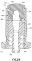
- system 132A includes a pierceable barrier membrane 402.
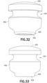
- Membrane 402 includes a first end 430, opposing second end 432, and an annular groove 434.
- membrane 402 is attachable to first end 410 of connector 400 by a press fit or interference fit.
- membrane 402 is attached to connector 400 by pressing membrane 402 within first end 410 of connector 400 such that annular protrusion 414 of connector engages annular groove 434 of membrane 402 to secure membrane 402 to connector 400 as shown in Fig. 29 .
- the assembly of the membrane 402 within a corresponding connector is described in more detail below.
- the first end 430 of the membrane 402 defines a convex surface.
- the second end 432 of the membrane 402 defines a cavity 403 that extends toward the first end 430 of the membrane 402.
- the cavity 403 terminates between the first end 430 and second end 432 of the membrane at about half a length of the membrane 402.
- the terminal end of the cavity 403 may define a concave surface, although other suitable shaped surfaces may be utilized.
- the cavity 403 tapers and narrows as it extends toward the first end 430 of the membrane 402.
- the second end 432 of the membrane 402 includes an annular projection 405 extending away from the second end 432 of the membrane 402.
- the pierceable barrier membrane 402 provides for a liquid and gas tight seal between a piercing member of a barrel assembly and the pierceable barrier membrane 402 during fluid transfer of a medication to a patient so to minimize leakage and thereby prevent exposure of hazardous medicaments to a user.
- Barrier membrane 402 provides a self-sealing seal that, with a barrel assembly attached to connector 400, provides a leak-proof seal preventing any substance being administered to a patient from being exposed to a health care provider administering the medication.
- barrier membrane 402 comprises a resilient material.
- barrier membrane 402 is preferably a unitary device molded of any flexible, elastomeric material conventionally used for fabricating gas-proof closures.
- Barrier membrane 402 may be formed of a natural rubber material, polyurethane elastomers, butyl rubbers, or similar materials.
- system 132A includes a male or first luer component 404.
- First luer component 404 includes first end 440, opposing second end 442, threaded portion 444, and membrane receiving portion 446.
- a female or second luer component 406 is attached to an end of IV line 408.
- the threaded portion 444 of first luer component 404 is engageable with a threaded portion 460 ( Fig. 35 ) of second luer component 406 to secure first luer component 404 to second luer component 406 and IV line 408 as shown in Fig. 35 .
- First luer component 404 is rotated in a clockwise direction generally along arrow CW ( Fig. 35 ) relative to second luer component 406 to tighten and secure threaded portion 444 of first luer component 404 to threaded portion 460 of second luer component 406.
- first luer component 404 is attachable to second end 412 of connector 400 by a press fit or interference fit.
- first luer component 404 is attached to connector 400 by pressing first luer component 404 within second end 412 of connector 400 such that second end 432 of membrane 402 engages membrane receiving portion 446 of first luer component 404 to secure first luer component 404, membrane 402, and connector 400 theretogether as shown in Fig. 29 .
- connection system 132A of the present disclosure to connect a first medical device component, e.g., injector adapter 12, to a second medical device component, e.g., connector 400, will now be described.
- first medical device component e.g., injector adapter 12
- second medical device component e.g., connector 400
- Connection system 132A includes similar steps as discussed in detail above with regards to connection system 132.
- the injector can be rotated in a clockwise direction generally along arrow CW to rotate the injector out of engagement with first securement element 140A of connector 400 and to disconnect the injector from connector 400.
- an overall connector 400 tightening to an IV line 408 results during the use of connection system 132A.
- rotation in a clockwise direction to disconnect the injector from connector 400 also causes the threaded portion 444 of first luer component 404 to tighten to threaded portion 460 of second luer component 406 thereby tightening connector 400 to IV line 408.
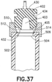
- the membrane 402 is assembled with a corresponding connector 502 by initial positioning the opposing end 432 of the membrane 402 within a central opening 504 of the connector 502 as shown in Fig. 36A .
- the membrane 402 is then pushed or forced into the opening 504 and past the annular protrusion 506 of the connector 502.
- the annular protrusion 506 compresses and engages the membrane 402 as the membrane 402 is inserted into the connector 502.
- the membrane 402 is pushed into the connector 502 until the annular groove 434 of the membrane 402 is aligned with and receives the annular protrusion 506 of the connector 502 thereby creating an interference fit between the connector 502 and the membrane 402.
- the intermediate portion of the membrane 402 between the first end 430 and the opposing end 432 of the membrane has an interference fit with the connector 502, which creates a positive internal pressure to promote self-sealing when pierced with a cannula or engaged with another connector.
- the first end 430 of the membrane extends beyond the connector 502 so that when the membrane 402 and connector 502 are mated with a corresponding membrane and connector, the first end 430 of the membrane is not restricted thereby improving the resealing performance of the membrane 402 when pierced by a cannula.
- an assembly tool 510 is provided to assist in the second step of inserting the membrane 402 within the connector 502.
- the assembly tool 510 includes a central opening 512 and a tapered surface 514, such as a frusto-conical shaped surface.
- the central opening 512 of the assembly tool 510 is aligned with the opening 504 of the connector 502.
- the membrane is then pushed and inserted into the opening 512 of the assembly tool 510 with the membrane 402 engaging the tapered surface 514 of the tool 510 to compress the membrane and allow for easier insertion of the membrane 402 into the connector 502.
- the membrane 402 is otherwise assembled with the connector 502 in the same manner as described above in connection with Figs. 36A-36C with the annular groove 434 of the membrane receiving the annular protrusion 506 of the connector 502.
Landscapes
- Health & Medical Sciences (AREA)
- Life Sciences & Earth Sciences (AREA)
- Animal Behavior & Ethology (AREA)
- General Health & Medical Sciences (AREA)
- Public Health (AREA)
- Veterinary Medicine (AREA)
- Heart & Thoracic Surgery (AREA)
- Pharmacology & Pharmacy (AREA)
- Fluid Mechanics (AREA)
- Physics & Mathematics (AREA)
- Pulmonology (AREA)
- Engineering & Computer Science (AREA)
- Anesthesiology (AREA)
- Biomedical Technology (AREA)
- Hematology (AREA)
- Infusion, Injection, And Reservoir Apparatuses (AREA)
- Medical Preparation Storing Or Oral Administration Devices (AREA)
- Separation Using Semi-Permeable Membranes (AREA)
- Electrotherapy Devices (AREA)
Claims (5)
- Medizinischer Konnektor mit:einem Konnektorkörper (400), der einen Innenraum definiert; undeinem Membrankörper (402) mit einem ersten Ende (430), das eine konvexe Fläche aufweist, und einem zweiten Ende (402), mit einer Seitenwand (114), die sich zwischen dem ersten Ende (430) und dem zweiten Ende (432) des Membrankörpers (402) erstreckt, wobei die Seitenwand eine ringförmige Ausnehmung (434) bildet, wobei das zweite Ende (432) des Membrankörpers (402) einen Hohlraum (403) definiert, der sich zum ersten Ende (430) des Körpers erstreckt, wobei die ringförmige Ausnehmung (434) zum Aufnehmen eines Teils des Konnektorkörpers (400) ausgebildet ist, wobei eine innere Ecke der ringförmigen Ausnehmung (434) abgerundet ist, ein ringförmiger Vorsprung (405) sich von dem zweiten Ende (432) des Membrankörpers (402) weg erstreckt, und der Hohlraum (403) sich derart verjüngt, dass der Hohlraum (403) sich mit seiner Erstreckung in Richtung des ersten Endes (430) des Membrankörpers (402) verengt, und wobei der Membrankörper (402) mittels Presspassung an dem Konnektorkörper (400) befestigt ist, und wobei ein Teil des Membrankörpers (402) in dem Innenraum des Konnektorkörpers (400) aufgenommen ist, wobei der Konnektorkörper (400) einen sich in den Innenraum des Konnektorkörpers (400) erstreckenden Vorsprung aufweist, wobei der Vorsprung des Konnektorkörpers (400) in der ringförmigen Ausnehmung (434) des Membrankörpers (402) aufgenommen ist.
- Medizinischer Konnektor nach Anspruch 1, bei welchem die Seitenwand (114) und die ringförmige Ausnehmung (404) des Membrankörpers (402) die Presspassung mit dem Konnektorkörper (400) herstellen.
- Medizinischer Konnektor nach Anspruch 1, bei welchem das erste Ende (430) des Membrankörpers (402) sich über den Konnektorkörper (400) hinaus erstreckt.
- Verfahren zum Zusammensetzen eines medizinischen Konnektors, mit den folgenden Schritten:Vorsehen eines Konnektorkörpers (400), der einen Innenraum definiert;Positionieren einer Membran nahe dem Konnektorkörper (400), wobei die Membran einen Membrankörper (402) mit einem ersten Ende (430), das eine konvexe Fläche aufweist, und einem zweiten Ende (402) aufweist, mit einer Seitenwand (114), die sich zwischen dem ersten Ende (430) und dem zweiten Ende (432) des Membrankörpers (402) erstreckt, wobei die Seitenwand eine ringförmige Ausnehmung (434) definiert, wobei das zweite Ende (432) des Membrankörpers (402) einen Hohlraum (403) bildet, der sich zum ersten Ende (430) des Körpers erstreckt, wobei die ringförmige Ausnehmung (434) zum Aufnehmen eines Teils des Konnektorkörpers (400) ausgebildet ist, wobei eine innere Ecke der ringförmigen Ausnehmung (434) abgerundet ist, ein ringförmiger Vorsprung (405) sich von dem zweiten Ende (432) des Membrankörpers (402) weg erstreckt, und der Hohlraum (403) sich derart verjüngt, dass der Hohlraum (403) sich mit seiner Erstreckung in Richtung des ersten Endes (430) des Membrankörpers (402) verengt; undEinführen eines Teils des Membrankörpers (402) in den Innenraum des Konnektorkörpers (400), und elastisches Verformen des Membrankörpers (402), um die Membran mittels Presspassung an dem Konnektorkörper (400) zu befestigen,wobei der Konnektorkörper (400) einen sich in den Innenraum des Konnektorkörpers (400) erstreckenden Vorsprung aufweist, wobei das Verfahren ferner den folgenden Schritt aufweist:
Positionieren des Vorsprungs des Konnektorkörpers (400) in der ringförmigen Ausnehmung (434) des Membrankörpers (402). - Verfahren nach Anspruch 4, ferner mit den Schritten:Positionieren eines Montagewerkzeugs an einem ersten Ende (410) des Konnektorkörpers (400) nahe dem Innenraum, wobei das Montagewerkzeug eine konische Fläche aufweist; undelastisches Verformen des Membrankörpers (402) vor dem Einführen des Teils des Membrankörpers in den Innenraum des Konnektorkörpers (400) durch Angreifen der konischen Fläche des Montagewerkzeugs an dem Teil des Membrankörpers (402).
Applications Claiming Priority (7)
| Application Number | Priority Date | Filing Date | Title |
|---|---|---|---|
| US201361787674P | 2013-03-15 | 2013-03-15 | |
| US201361895187P | 2013-10-24 | 2013-10-24 | |
| US201361895182P | 2013-10-24 | 2013-10-24 | |
| US201361895168P | 2013-10-24 | 2013-10-24 | |
| EP14717288.6A EP2968067B1 (de) | 2013-03-15 | 2014-03-12 | Verbindungssystem für komponenten medizinischer vorrichtungen |
| PCT/US2014/023911 WO2014150665A2 (en) | 2013-03-15 | 2014-03-12 | Connection system for medical device components |
| EP17168954.0A EP3219354B1 (de) | 2013-03-15 | 2014-03-12 | Verbindungssystem für komponenten medizinischer vorrichtungen |
Related Parent Applications (2)
| Application Number | Title | Priority Date | Filing Date |
|---|---|---|---|
| EP14717288.6A Division EP2968067B1 (de) | 2013-03-15 | 2014-03-12 | Verbindungssystem für komponenten medizinischer vorrichtungen |
| EP17168954.0A Division EP3219354B1 (de) | 2013-03-15 | 2014-03-12 | Verbindungssystem für komponenten medizinischer vorrichtungen |
Publications (3)
| Publication Number | Publication Date |
|---|---|
| EP3831439A1 EP3831439A1 (de) | 2021-06-09 |
| EP3831439B1 true EP3831439B1 (de) | 2023-06-07 |
| EP3831439C0 EP3831439C0 (de) | 2023-06-07 |
Family
ID=50390303
Family Applications (5)
| Application Number | Title | Priority Date | Filing Date |
|---|---|---|---|
| EP20216112.1A Active EP3831439B1 (de) | 2013-03-15 | 2014-03-12 | Verbindungssystem für komponenten medizinischer vorrichtungen |
| EP14717288.6A Active EP2968067B1 (de) | 2013-03-15 | 2014-03-12 | Verbindungssystem für komponenten medizinischer vorrichtungen |
| EP14713746.7A Active EP2968065B1 (de) | 2013-03-15 | 2014-03-12 | System für geschlossenen transfer von flüssigkeiten |
| EP19153599.6A Active EP3494951B1 (de) | 2013-03-15 | 2014-03-12 | System für geschlossenen transfer von flüssigkeiten |
| EP17168954.0A Active EP3219354B1 (de) | 2013-03-15 | 2014-03-12 | Verbindungssystem für komponenten medizinischer vorrichtungen |
Family Applications After (4)
| Application Number | Title | Priority Date | Filing Date |
|---|---|---|---|
| EP14717288.6A Active EP2968067B1 (de) | 2013-03-15 | 2014-03-12 | Verbindungssystem für komponenten medizinischer vorrichtungen |
| EP14713746.7A Active EP2968065B1 (de) | 2013-03-15 | 2014-03-12 | System für geschlossenen transfer von flüssigkeiten |
| EP19153599.6A Active EP3494951B1 (de) | 2013-03-15 | 2014-03-12 | System für geschlossenen transfer von flüssigkeiten |
| EP17168954.0A Active EP3219354B1 (de) | 2013-03-15 | 2014-03-12 | Verbindungssystem für komponenten medizinischer vorrichtungen |
Country Status (8)
| Country | Link |
|---|---|
| US (7) | US9597260B2 (de) |
| EP (5) | EP3831439B1 (de) |
| JP (4) | JP6091698B2 (de) |
| CN (6) | CN104107141B (de) |
| CA (4) | CA2980186C (de) |
| ES (5) | ES2720429T3 (de) |
| IL (5) | IL290081B2 (de) |
| WO (2) | WO2014150665A2 (de) |
Families Citing this family (101)
| Publication number | Priority date | Publication date | Assignee | Title |
|---|---|---|---|---|
| US20070202186A1 (en) | 2006-02-22 | 2007-08-30 | Iscience Interventional Corporation | Apparatus and formulations for suprachoroidal drug delivery |
| US7547300B2 (en) | 2006-04-12 | 2009-06-16 | Icu Medical, Inc. | Vial adaptor for regulating pressure |
| US7883499B2 (en) | 2007-03-09 | 2011-02-08 | Icu Medical, Inc. | Vial adaptors and vials for regulating pressure |
| WO2010022095A1 (en) | 2008-08-20 | 2010-02-25 | Icu Medical, Inc. | Anti-reflux vial adaptors |
| AU2010276522B2 (en) | 2009-07-29 | 2016-03-10 | Icu Medical, Inc. | Fluid transfer devices and methods of use |
| JP5996544B2 (ja) | 2010-10-15 | 2016-09-21 | クリアサイド・バイオメディカル・インコーポレーテッドClearside Biomedical Incorporated | 眼球アクセス用装置 |
| EP2680807B1 (de) * | 2011-03-04 | 2016-08-10 | Duoject Medical Systems Inc. | Einfaches verknüpfungsübertragungssystem |
| WO2013025946A1 (en) | 2011-08-18 | 2013-02-21 | Icu Medical, Inc. | Pressure-regulating vial adaptors |
| AU2012324021A1 (en) | 2011-12-22 | 2013-07-11 | Icu Medical, Inc. | Fluid transfer devices and methods of use |
| CN104168948B (zh) | 2012-01-13 | 2017-03-01 | Icu医学有限公司 | 控压型管形瓶接头和方法 |
| SG192310A1 (en) | 2012-02-02 | 2013-08-30 | Becton Dickinson Holdings Pte Ltd | Adaptor for coupling to a medical container |
| WO2013142618A1 (en) | 2012-03-22 | 2013-09-26 | Icu Medical, Inc. | Pressure-regulating vial adaptors |
| US9724269B2 (en) * | 2012-11-30 | 2017-08-08 | Becton Dickinson and Company Ltd. | Connector for fluid communication |
| AU2014209594B2 (en) | 2013-01-23 | 2018-09-13 | Icu Medical, Inc. | Pressure-regulating vial adaptors |
| US9089475B2 (en) | 2013-01-23 | 2015-07-28 | Icu Medical, Inc. | Pressure-regulating vial adaptors |
| US9101717B2 (en) * | 2013-03-12 | 2015-08-11 | Carefusion 303, Inc. | Non-vented vial access syringe |
| WO2014143584A1 (en) * | 2013-03-14 | 2014-09-18 | Pharmajet Inc. | Vial adapter for a needle-free syringe |
| US9597260B2 (en) | 2013-03-15 | 2017-03-21 | Becton Dickinson and Company Ltd. | System for closed transfer of fluids |
| US9414990B2 (en) * | 2013-03-15 | 2016-08-16 | Becton Dickinson and Company Ltd. | Seal system for cannula |
| BR112015027762A2 (pt) | 2013-05-03 | 2017-08-29 | Clearside Biomedical Inc | Aparelho e métodos para injeção ocular |
| WO2014186800A1 (en) * | 2013-05-17 | 2014-11-20 | Carrtech Llc | Filtering needle cap |
| AU2014290124B2 (en) | 2013-07-19 | 2019-05-09 | Icu Medical, Inc. | Pressure-regulating fluid transfer systems and methods |
| AU2014353184B2 (en) | 2013-11-25 | 2017-08-17 | Icu Medical, Inc. | Methods and system for filling IV bags with therapeutic fluid |
| USD741477S1 (en) * | 2014-01-17 | 2015-10-20 | Rocomp Global, Llc | Radiant energy guide |
| WO2015164385A1 (en) * | 2014-04-21 | 2015-10-29 | Becton Dickinson and Company Limited | System with adapter for closed transfer of fluids |
| CA2953229C (en) | 2014-06-20 | 2024-01-02 | Icu Medical, Inc. | Pressure-regulating vial adaptors |
| IL237788B (en) * | 2015-03-16 | 2019-10-31 | Kriheli Marino | Septum holders used in injector connectors |
| CN104800079A (zh) * | 2015-04-27 | 2015-07-29 | 山东威高集团医用高分子制品股份有限公司 | 一种密闭药物转移装置 |
| IL239366B (en) * | 2015-06-11 | 2018-07-31 | Kriheli Marino | Components of a fluid transfer apparatus |
| AU2016276956B2 (en) | 2015-06-12 | 2018-08-09 | Becton Dickinson and Company Limited | Syringe adapter with spinning connector |
| EP3380058B1 (de) * | 2015-11-25 | 2020-01-08 | West Pharma Services IL, Ltd. | Dualphiolenadapteranordnung mit arzneimittelphiolenadapter mit selbstverschliessendem zugangsventil |
| FR3044218B1 (fr) | 2015-11-30 | 2017-12-29 | Biocorp Prod | Dispositif de connexion entre un recipient et un contenant, ensemble de connexion comprenant un tel dispositif |
| JP6426682B2 (ja) * | 2015-11-30 | 2018-11-21 | ベクトン・ディキンソン・アンド・カンパニーBecton, Dickinson And Company | 短い注射長さの注射器 |
| WO2017096072A1 (en) | 2015-12-04 | 2017-06-08 | Icu Medical, Inc. | Systems methods and components for transferring medical fluids |
| KR102209807B1 (ko) * | 2015-12-08 | 2021-01-29 | 벡톤 디킨슨 프랑스 | 의료용 주입기용 반구형 부분을 구비한 캡 |
| CA3012733C (en) | 2016-01-29 | 2023-09-12 | Icu Medical, Inc. | Pressure-regulating vial adaptors |
| FR3049467B1 (fr) * | 2016-03-31 | 2021-12-10 | Sartorius Stedim Fmt Sas | Port, systeme de distribution comprenant un tel port, et procede de fabrication |
| EP3461259B1 (de) | 2016-05-16 | 2021-01-06 | Haemonetics Corporation | Versieglerlose plasmaflasche und deckel dafür |
| US11648179B2 (en) | 2016-05-16 | 2023-05-16 | Haemonetics Corporation | Sealer-less plasma bottle and top for same |
| MX2018014078A (es) * | 2016-05-20 | 2019-04-04 | Tuthill Corp | Ensamble de adaptador de medicion para sistema de transferencia de fluido de bucle cerrado. |
| US10365141B2 (en) | 2016-05-20 | 2019-07-30 | Tuthill Corporation | Measuring adapter assembly for closed loop fluid transfer system |
| DE102016110569B3 (de) * | 2016-06-08 | 2017-10-26 | Sfm Medical Devices Gmbh | Adapter |
| JP6747080B2 (ja) * | 2016-06-15 | 2020-08-26 | 株式会社ジェイ・エム・エス | 空気吸引用キャップ |
| USD851745S1 (en) | 2016-07-19 | 2019-06-18 | Icu Medical, Inc. | Medical fluid transfer system |
| EP3487468B1 (de) | 2016-07-25 | 2025-10-01 | ICU Medical, Inc. | Systeme und komponenten zum einfangen von luftblasen in medizinischen flüssigkeitstransfermodulen und systemen |
| IL305537B2 (en) | 2016-08-12 | 2025-02-01 | Clearside Biomedical Inc | Devices and methods for adjusting the insertion depth of a needle for administering a drug |
| CN109640920B (zh) | 2016-08-22 | 2022-06-07 | 伊莱利利公司 | 安全的药物转移系统 |
| JP7063891B2 (ja) | 2016-09-30 | 2022-05-09 | アイシーユー・メディカル・インコーポレーテッド | バイアルアダプタ |
| SG11201901156PA (en) | 2016-10-20 | 2019-03-28 | Emd Millipore Corp | Valve protection and tube management device |
| IL268043B2 (en) * | 2017-01-17 | 2023-10-01 | Becton Dickinson & Co Ltd | Connector for a closed fluid transfer system |
| CA3050461A1 (en) | 2017-01-17 | 2018-07-26 | Becton Dickinson and Company Limited | Syringe adapter for closed transfer of fluids |
| CA3050463A1 (en) | 2017-01-17 | 2018-07-26 | Becton Dickinson and Company Limited | Syringe adapter with lock mechanism |
| EP3570806B1 (de) | 2017-01-17 | 2025-10-15 | Becton Dickinson and Company Limited | Spritzenadapter |
| CA3050433A1 (en) | 2017-01-17 | 2018-07-26 | Becton Dickinson and Company Limited | Syringe adapter with cap |
| US11197803B2 (en) * | 2017-03-24 | 2021-12-14 | Carefusion 303, Inc. | Needleless cartridge for automatic drug compounder |
| JP7150703B2 (ja) * | 2017-04-03 | 2022-10-11 | 大和製罐株式会社 | 接続器具、及び、器具接続具 |
| US10857343B2 (en) | 2017-04-06 | 2020-12-08 | Becton, Dickinson And Company | Medical devices with visual and tactile indicators |
| USD835269S1 (en) * | 2017-04-06 | 2018-12-04 | Becton, Dickinson And Company | Syringe tip with indicator |
| USD835268S1 (en) * | 2017-04-06 | 2018-12-04 | Becton, Dickinson And Company | Syringe tip with indicator |
| JP6945641B2 (ja) * | 2017-05-19 | 2021-10-06 | エーディーヴィーケア メディカル インコーポレイテッド | 密閉システム調剤投薬装置 |
| DE102017005791B4 (de) * | 2017-06-21 | 2023-08-10 | Jan Willem Marinus Mijers | Transfervorrichtung zur Fluidübertragung |
| CN107158492A (zh) * | 2017-07-04 | 2017-09-15 | 宁波鸿坤电器有限公司 | 一种引流针 |
| BE1025530B1 (nl) * | 2017-07-18 | 2019-04-05 | Atlas Copco Airpower Naamloze Vennootschap | Een filtersysteem voor het scheiden van vloeistof uit samengeperst gas en compressor omvattende een dergelijk filtersysteem |
| JP6929733B2 (ja) * | 2017-07-31 | 2021-09-01 | 大和製罐株式会社 | 容器接続具、及び、接続器具 |
| ES3039790T3 (en) * | 2017-11-02 | 2025-10-24 | Hoffmann La Roche | Container adapter and delivery assembly of a liquid to a patient |
| US10426700B2 (en) | 2017-11-28 | 2019-10-01 | International Business Machines Corporation | Syringe accessory for transfer of air sensitive materials |
| CN111526855B (zh) * | 2018-01-04 | 2024-06-07 | 爱康医学农业合作协会有限公司 | 用于封闭流体输送系统的药瓶适配器组件 |
| RU2752601C1 (ru) * | 2018-02-06 | 2021-07-29 | Бектон, Дикинсон Энд Компани | Система сбора и стабилизации биологических жидкостей |
| USD907193S1 (en) | 2018-02-21 | 2021-01-05 | Eli Lilly And Company | Secured medication transfer set |
| TWI645871B (zh) | 2018-03-19 | 2019-01-01 | 蔡溪進 | 防止藥液或體液外漏之輸液封閉型接頭 |
| AU2019238179B2 (en) | 2018-03-20 | 2021-12-23 | Becton Dickinson and Company Limited | Connection arrangement for closed system transfer of fluids |
| USD877900S1 (en) | 2018-04-04 | 2020-03-10 | Becton Dickinson and Company Limited | Medical infusion adapter |
| USD873996S1 (en) | 2018-04-04 | 2020-01-28 | Becton Dickinson and Company Limited | Medical syringe adapter |
| USD908872S1 (en) | 2018-04-04 | 2021-01-26 | Becton Dickinson and Company Limited | Medical vial access device |
| USD888945S1 (en) | 2018-04-04 | 2020-06-30 | Becton Dickinson and Company Limited | Medical connector |
| CN110384858B (zh) * | 2018-04-18 | 2021-05-18 | 蔡溪进 | 防止药液或体液外漏的输液封闭型接头 |
| JP7068497B2 (ja) * | 2018-04-19 | 2022-05-16 | ベクトン ディキンソン アンド カンパニー リミテッド | 吸引アセンブリ付きシリンジアダプタ |
| JP7289320B2 (ja) * | 2018-05-25 | 2023-06-09 | ベクトン ディキンソン フランス | 医療用注射装置を容器に接続するためのコネクタ |
| WO2020050875A2 (en) * | 2018-09-07 | 2020-03-12 | Becton, Dickinson And Company | SYRINGE ASSEMBLY and ADAPTER MEMBER |
| HRP20241408T1 (hr) | 2018-10-03 | 2024-12-20 | Takeda Pharmaceutical Company Limited | Ambalaža za više spremnika |
| US11266779B2 (en) * | 2019-03-04 | 2022-03-08 | Carefusion 303, Inc. | IV set spike with enhanced removal force |
| US11760001B2 (en) * | 2019-03-29 | 2023-09-19 | Stratasys, Inc. | Filament supply with sealed connector for use with a 3D printer |
| EP4603074A3 (de) * | 2019-07-03 | 2025-10-15 | Becton, Dickinson and Company | Medizinische vorrichtung, medizinische vorrichtungsanordnung damit und verfahren zur rekonstitution einer pharmazeutischen zusammensetzung |
| US11478406B1 (en) * | 2019-09-09 | 2022-10-25 | Chris C. Rutter | Aseptic filling apparatus and method |
| US10945922B1 (en) * | 2019-09-26 | 2021-03-16 | Abyssal Systems, Inc. | Apparatus for creating a sealed conduit between separate volumes |
| CN113208916B (zh) * | 2020-01-21 | 2024-12-13 | 贝克顿·迪金森公司 | 药瓶适配器装置 |
| IL314250A (en) * | 2020-02-21 | 2024-09-01 | Bayer Healthcare Llc | Fluid path connectors for administering medical fluids |
| DE102020202941A1 (de) | 2020-03-06 | 2021-09-09 | B. Braun Melsungen Aktiengesellschaft | Kupplungselement und Kupplungssystem für ein geschlossenes Fluidtransfersystem |
| DE102020202939A1 (de) | 2020-03-06 | 2021-09-09 | B. Braun Melsungen Aktiengesellschaft | Kupplungselement für ein geschlossenes Fluidtransfersystem, Gegenkupplungselement für ein solches Kupplungselement sowie Kupplungssystem |
| DE102020202935A1 (de) | 2020-03-06 | 2021-09-09 | B. Braun Melsungen Aktiengesellschaft | Kupplungselement für ein geschlossenes Fluidtransfersystem, Gegenkupplungselement für ein solches Kupplungselement sowie Kupplungssystem |
| CN111297683B (zh) * | 2020-03-20 | 2021-05-07 | 江苏苏云医疗器材有限公司 | 一种安全型药液转移器 |
| US11590057B2 (en) | 2020-04-03 | 2023-02-28 | Icu Medical, Inc. | Systems, methods, and components for transferring medical fluids |
| CN113243309A (zh) * | 2020-06-03 | 2021-08-13 | 深圳市溯安智能科技有限公司 | 一种具有拍摄功能的耳标钳及用其采集信息的方法 |
| WO2022055064A1 (ko) * | 2020-09-10 | 2022-03-17 | 주식회사 보틀리스 | 저장 용기 및 이의 액체 주입 방법 |
| WO2022093878A1 (en) * | 2020-10-28 | 2022-05-05 | Becton, Dickinson And Company | Membrane with guide surface |
| CN113289137B (zh) * | 2021-05-24 | 2022-10-18 | 枣庄市肿瘤医院(枣庄市胸科医院) | 基于自密封性密封塞结构的植入式医疗装置 |
| CN113598768B (zh) * | 2021-07-27 | 2023-05-09 | 天津云帆医疗器械有限公司 | 采血笔 |
| JP2024529125A (ja) * | 2021-08-12 | 2024-08-01 | ベクトン・ディキンソン・アンド・カンパニー | 注射針ハブを有する注射器アダプタ |
| CN115607445B (zh) * | 2022-07-01 | 2024-03-01 | 广东健力源医疗科技有限公司 | 一种侧导管型全封闭式安全配药装置 |
| JP2025533029A (ja) | 2022-10-01 | 2025-10-03 | カーテック コーポレーション | シールプラグを備えたフィルターニードル組立体 |
| US12329721B1 (en) | 2024-12-20 | 2025-06-17 | Applied Cells Inc. | System and method for aseptically transferring fluid |
Family Cites Families (178)
| Publication number | Priority date | Publication date | Assignee | Title |
|---|---|---|---|---|
| US3047178A (en) * | 1958-06-24 | 1962-07-31 | Baxter Laboratories Inc | Closure system |
| JPS5043056Y2 (de) | 1971-02-27 | 1975-12-09 | ||
| JPS5418522Y2 (de) * | 1973-08-17 | 1979-07-12 | ||
| JPS5043056A (de) | 1973-08-20 | 1975-04-18 | ||
| US4296786A (en) * | 1979-09-28 | 1981-10-27 | The West Company | Transfer device for use in mixing a primary solution and a secondary or additive substance |
| SE434700B (sv) * | 1983-05-20 | 1984-08-13 | Bengt Gustavsson | Anordning for lufttet overforing av substans fran ett kerl till ett annat |
| DE3483475D1 (de) | 1983-05-20 | 1990-11-29 | Bengt Gustavsson | Anordnung zur uebertragung einer substanz. |
| US4589879A (en) * | 1983-11-04 | 1986-05-20 | Baxter Travenol Laboratories, Inc. | Cannula assembly having closed, pressure-removable piercing tip |
| JPS6131441U (ja) * | 1984-07-31 | 1986-02-25 | 株式会社 大協ゴム精工 | 樹脂ラミネ−ト医薬品用ゴム栓 |
| EP0331680B1 (de) | 1986-11-06 | 1991-09-04 | Bengt Gustavsson | Behälter für lagerung oder sammlung von flüssigkeiten und trockenen substanzen |
| JPH0341719Y2 (de) * | 1987-04-20 | 1991-09-02 | ||
| US5334188A (en) | 1987-12-07 | 1994-08-02 | Nissho Corporation | Connector with injection site |
| US5211638A (en) * | 1988-01-25 | 1993-05-18 | Baxter International Inc. | Pre-slit injection site |
| JPH0748271Y2 (ja) * | 1989-12-19 | 1995-11-08 | 日本シャーウッド株式会社 | 液体混注具 |
| US5122129A (en) | 1990-05-09 | 1992-06-16 | Olson Donald J | Sampler coupler device useful in the medical arts |
| JPH04210070A (ja) * | 1990-12-11 | 1992-07-31 | Sekisui Chem Co Ltd | 混注部の製造方法 |
| US5122123A (en) * | 1991-01-30 | 1992-06-16 | Vaillancourt Vincent L | Closed system connector assembly |
| DK0988871T3 (da) | 1991-12-18 | 2004-05-24 | Icu Medical Inc | Fremgangsmåde til overføring af fluid |
| SE9203659L (sv) | 1992-12-04 | 1994-02-14 | Dicamed Ab | Ventilanordning för aseptisk injicering och uttag av medicinsk vätska i/ur behållare samt dess användning |
| US5478328A (en) | 1992-05-22 | 1995-12-26 | Silverman; David G. | Methods of minimizing disease transmission by used hypodermic needles, and hypodermic needles adapted for carrying out the method |
| GB9211912D0 (en) | 1992-06-04 | 1992-07-15 | Drg Flexpak Ltd | Vial connector system |
| AU4999793A (en) * | 1992-08-07 | 1994-03-03 | West Company, Incorporated, The | Needleless access stopper |
| US5290254A (en) | 1992-11-16 | 1994-03-01 | Vaillancourt Vincent L | Shielded cannula assembly |
| US5509911A (en) | 1992-11-27 | 1996-04-23 | Maxxim Medical, Inc. | Rotating adapter for a catheterization system |
| WO1994023775A1 (en) | 1993-03-23 | 1994-10-27 | Abbott Laboratories | Securing collar for cannula connector |
| US5280876A (en) | 1993-03-25 | 1994-01-25 | Roger Atkins | Limited restriction quick disconnect valve |
| US5395348A (en) | 1993-05-04 | 1995-03-07 | Symbiosis Corporation | Medical intravenous administration line connectors |
| US5360011A (en) | 1993-07-13 | 1994-11-01 | Mccallister Teresa D | Blood sample collection |
| US5472430A (en) | 1993-08-18 | 1995-12-05 | Vlv Associates | Protected needle assembly |
| CA2170160C (en) * | 1993-09-07 | 2002-08-27 | Frederic Neftel | Syringe device for mixing two compounds |
| US7033339B1 (en) * | 1998-05-29 | 2006-04-25 | Becton Dickinson And Company (Part Interest) | Self sealing luer receiving stopcock |
| US5609584A (en) | 1994-05-18 | 1997-03-11 | Gettig Technologies, Inc. | Adaptor system for use with a syringe |
| US5487728A (en) | 1994-05-19 | 1996-01-30 | Vaillancourt; Vincent L. | Connector assembly |
| DE69528063T2 (de) | 1994-06-24 | 2003-06-05 | Icu Medical, Inc. | Vorrichtung zur überleitung einer flüssigkeit und methode zur anwendung |
| US5545152A (en) | 1994-10-28 | 1996-08-13 | Minimed Inc. | Quick-connect coupling for a medication infusion system |
| FR2726768A1 (fr) * | 1994-11-14 | 1996-05-15 | Debiotech Sa | Dispositif de seringue fixable sur un flacon |
| US5607392A (en) | 1995-01-13 | 1997-03-04 | Ryder International Corporation | Fixed needle connector for IV assembly and method of assembling |
| US5647845A (en) | 1995-02-01 | 1997-07-15 | Habley Medical Technology Corporation | Generic intravenous infusion system |
| IL114960A0 (en) * | 1995-03-20 | 1995-12-08 | Medimop Medical Projects Ltd | Flow control device |
| SE509950C2 (sv) | 1995-05-02 | 1999-03-29 | Carmel Pharma Ab | Anordning för administrering av toxisk vätska |
| US5700248A (en) | 1995-12-15 | 1997-12-23 | Icu Medical, Inc. | Medical valve with tire seal |
| US5807347A (en) | 1995-12-21 | 1998-09-15 | Bonaldo; Jean M. | Medical valve element |
| WO1997025015A1 (en) * | 1996-01-11 | 1997-07-17 | Duoject Medical Systems Inc. | Delivery system for pharmaceuticals packed in pharmaceutical vials |
| US5897526A (en) | 1996-06-26 | 1999-04-27 | Vaillancourt; Vincent L. | Closed system medication administering system |
| US6221056B1 (en) | 1996-12-20 | 2001-04-24 | David G. Silverman | Strong diaphragm/safe needle units and components for transfer of fluids |
| US6089541A (en) | 1998-09-10 | 2000-07-18 | Halkey-Roberts Corporation | Valve having a valve body and a deformable stem therein |
| IT236233Y1 (it) | 1997-11-26 | 2000-08-08 | Eurospital S P A | Dispositivo per il collegamento di un contenitore di prodottofarmaceutico ad una sacca di prodotto liquido per effettuare il |
| US6090092A (en) | 1997-12-04 | 2000-07-18 | Baxter International Inc. | Sliding reconstitution device with seal |
| DE19828651C2 (de) | 1998-06-26 | 2000-07-13 | Fresenius Medical Care De Gmbh | Konnektorelement mit Verschlußteil für die Medizintechnik |
| US6358236B1 (en) | 1998-08-06 | 2002-03-19 | Baxter International Inc. | Device for reconstituting medicaments for injection |
| US6022339A (en) | 1998-09-15 | 2000-02-08 | Baxter International Inc. | Sliding reconstitution device for a diluent container |
| AR021220A1 (es) | 1998-09-15 | 2002-07-03 | Baxter Int | DISPOSITIVO DE CONEXIoN PARA ESTABLECER UNA COMUNICACIoN FLUíDA ENTRE UN PRIMER RECIPIENTE Y UN SEGUNDO RECIPIENTE. |
| US6113068A (en) * | 1998-10-05 | 2000-09-05 | Rymed Technologies | Swabbable needleless injection port system having low reflux |
| WO2000025844A1 (en) | 1998-10-29 | 2000-05-11 | Minimed Inc. | Compact pump drive system |
| US20020173748A1 (en) | 1998-10-29 | 2002-11-21 | Mcconnell Susan | Reservoir connector |
| FR2789369B1 (fr) | 1999-02-10 | 2001-04-27 | Biodome | Dispositif de connexion entre un recipient et un contenant et ensemble pret a l'emploi comprenant un tel dispositif |
| FR2790948B1 (fr) * | 1999-03-18 | 2001-06-22 | Sedat | Dispositif de transfert bidirectionnel d'un liquide entre un flacon et une capsule |
| US6832994B2 (en) | 2000-01-24 | 2004-12-21 | Bracco Diagnostics Inc. | Table top drug dispensing vial access adapter |
| US6544246B1 (en) | 2000-01-24 | 2003-04-08 | Bracco Diagnostics, Inc. | Vial access adapter and vial combination |
| US6139534A (en) | 2000-01-24 | 2000-10-31 | Bracco Diagnostics, Inc. | Vial access adapter |
| US7100646B2 (en) | 2000-02-11 | 2006-09-05 | Medical Instill Technologies, Inc. | Sealed containers and methods of making and filling same |
| SE0001278L (sv) | 2000-04-06 | 2001-10-08 | Peter Unger Med P U Med Konsul | Sterilkoppling |
| JP4372310B2 (ja) | 2000-04-10 | 2009-11-25 | ニプロ株式会社 | 混注用アダプター |
| US6343629B1 (en) | 2000-06-02 | 2002-02-05 | Carmel Pharma Ab | Coupling device for coupling a vial connector to a drug vial |
| US6629958B1 (en) | 2000-06-07 | 2003-10-07 | Ronald P. Spinello | Leak sealing needle |
| SE517084C2 (sv) | 2000-08-10 | 2002-04-09 | Carmel Pharma Ab | Förfarande och anordningar vid aseptisk beredning |
| JP4043712B2 (ja) * | 2000-11-30 | 2008-02-06 | 株式会社吉野工業所 | 合成樹脂製中栓付きの容器 |
| FR2819174B1 (fr) | 2001-01-08 | 2003-06-13 | Pierre Frezza | Ampoule pour le conditionnement et le transfert d'un liquide ou d'une poudre a usage medical dans un contenant |
| US6474375B2 (en) | 2001-02-02 | 2002-11-05 | Baxter International Inc. | Reconstitution device and method of use |
| JP2002306610A (ja) * | 2001-02-09 | 2002-10-22 | Fukai Kogyo Kk | 薬液等注入抽出口用シール弁 |
| US6656433B2 (en) | 2001-03-07 | 2003-12-02 | Churchill Medical Systems, Inc. | Vial access device for use with various size drug vials |
| US7470258B2 (en) * | 2001-03-13 | 2008-12-30 | Mdc Investment Holdings, Inc. | Pre-filled safety vial injector |
| US7004934B2 (en) | 2001-09-06 | 2006-02-28 | Vaillancourt Vincent L | Closed system connector assembly |
| US6715520B2 (en) | 2001-10-11 | 2004-04-06 | Carmel Pharma Ab | Method and assembly for fluid transfer |
| JP3972665B2 (ja) | 2002-01-25 | 2007-09-05 | 株式会社ジェイ・エム・エス | 無菌接続コネクタシステム |
| US6911025B2 (en) | 2002-01-25 | 2005-06-28 | Jms Co., Ltd. | Connector system for sterile connection |
| US6875205B2 (en) | 2002-02-08 | 2005-04-05 | Alaris Medical Systems, Inc. | Vial adapter having a needle-free valve for use with vial closures of different sizes |
| US7744581B2 (en) | 2002-04-08 | 2010-06-29 | Carmel Pharma Ab | Device and method for mixing medical fluids |
| US7867215B2 (en) | 2002-04-17 | 2011-01-11 | Carmel Pharma Ab | Method and device for fluid transfer in an infusion system |
| US7350535B2 (en) | 2002-04-26 | 2008-04-01 | Gl Tool And Manufacturing Co. Inc. | Valve |
| ES2355615T3 (es) | 2002-04-26 | 2011-03-29 | Millipore Corporation | Dispositivo de transferencia de fluido estéril desechable. |
| ES2301826T3 (es) | 2002-07-09 | 2008-07-01 | Carmel Pharma Ab | Un dispositivo de inyeccion de sustancias medicas. |
| SE523001C2 (sv) | 2002-07-09 | 2004-03-23 | Carmel Pharma Ab | En kopplingsdel, en koppling, en infusionspåse, en infusionsanordning och ett förfarande för överföring av medicinska substanser |
| AU2003281876A1 (en) * | 2002-11-08 | 2004-06-07 | Duoject Medical Systems Inc. | Pharmaceutical delivery systems and methods for using same |
| JP2004189265A (ja) * | 2002-12-10 | 2004-07-08 | Teruaki Ito | チューブ形検体容器用の栓 |
| JP2004244074A (ja) * | 2003-02-14 | 2004-09-02 | Alcoa Closure Systems Japan Ltd | キャップ、閉止装置、および容器詰め飲料 |
| US7040598B2 (en) | 2003-05-14 | 2006-05-09 | Cardinal Health 303, Inc. | Self-sealing male connector |
| US20040249235A1 (en) | 2003-06-03 | 2004-12-09 | Connell Edward G. | Hazardous material handling system and method |
| GB0317175D0 (en) | 2003-07-23 | 2003-08-27 | Liversidge Barry P | Medical needle system |
| WO2005011798A1 (ja) | 2003-07-31 | 2005-02-10 | Jms Co., Ltd. | 医療用コネクタシステム |
| US7390321B2 (en) | 2003-09-18 | 2008-06-24 | Advanced Technology Materials, Inc. | Connection having laminar flow for the delivery of a substance |
| SI2463201T1 (sl) * | 2003-10-30 | 2014-06-30 | Teva Medical Ltd. | Naprava za varno obdelavo zdravila |
| JP4744074B2 (ja) | 2003-12-01 | 2011-08-10 | ルネサスエレクトロニクス株式会社 | 表示メモリ回路および表示コントローラ |
| US20080287914A1 (en) | 2003-12-22 | 2008-11-20 | Philip Wyatt | Medicament administration apparatus |
| US7530546B2 (en) * | 2004-01-13 | 2009-05-12 | Rymed Technologies, Inc. | Swabbable needle-free injection port valve system with zero fluid displacement |
| IL161660A0 (en) * | 2004-04-29 | 2004-09-27 | Medimop Medical Projects Ltd | Liquid drug delivery device |
| EP1787667A4 (de) | 2004-08-04 | 2010-07-07 | Ajinomoto Kk | Kommunizierende nadel für die kommunikation von zwei oder mehr behältern |
| US7731678B2 (en) | 2004-10-13 | 2010-06-08 | Hyprotek, Inc. | Syringe devices and methods for mixing and administering medication |
| US20080045919A1 (en) | 2004-12-23 | 2008-02-21 | Bracco Research S.A. | Liquid Transfer Device for Medical Dispensing Containers |
| JP4647365B2 (ja) | 2005-03-31 | 2011-03-09 | 日本シャーウッド株式会社 | 医療用の接続器具 |
| US7648491B2 (en) | 2005-05-13 | 2010-01-19 | Bob Rogers | Medical substance transfer system |
| GB0510057D0 (en) * | 2005-05-17 | 2005-06-22 | Glaxosmithkline Biolog Sa | Novel device |
| US20070088292A1 (en) | 2005-07-06 | 2007-04-19 | Fangrow Thomas F Jr | Medical connector with closeable male luer |
| EP1909735A1 (de) * | 2005-08-01 | 2008-04-16 | Medimop Medical Projects Ltd. | System zur abgabe eines flüssigenarzneimittels |
| AU2006348410B2 (en) | 2005-11-07 | 2011-12-15 | Industrie Borla S.P.A. | Vented safe handling vial adapter |
| DE602006008666D1 (de) * | 2005-11-30 | 2009-10-01 | Biocorp Rech Et Dev | Steckvorrichtung für einen container und mit einer solchen vorrichtung ausgestatteter container |
| EP1797919A1 (de) | 2005-12-16 | 2007-06-20 | Bracco Research S.A. | Vorrichtung zum Übertragen von Flüssigkeiten für Behälter zur Abgabe von Medikamenten |
| AT503142B1 (de) | 2006-01-18 | 2009-05-15 | Friedrich Ing Pipelka | Behälter zur einbringung zumindest eines unsterilen gefässes in einen sterilen bereich |
| US7547300B2 (en) | 2006-04-12 | 2009-06-16 | Icu Medical, Inc. | Vial adaptor for regulating pressure |
| JP4973661B2 (ja) * | 2006-06-19 | 2012-07-11 | ニプロ株式会社 | 薬液調製用キット |
| US8257286B2 (en) | 2006-09-21 | 2012-09-04 | Tyco Healthcare Group Lp | Safety connector apparatus |
| US7670326B2 (en) * | 2006-09-25 | 2010-03-02 | Teva Medical Ltd.. | Syringe adapter element in drug mixing system |
| US8167863B2 (en) | 2006-10-16 | 2012-05-01 | Carefusion 303, Inc. | Vented vial adapter with filter for aerosol retention |
| JP2008105461A (ja) | 2006-10-23 | 2008-05-08 | Chiang-Fen Lin | 車輌の側方ウインドウのワイパー構造 |
| AU2007308835A1 (en) | 2006-10-25 | 2008-05-02 | Icu Medical, Inc. | Medical connector |
| US7900659B2 (en) | 2006-12-19 | 2011-03-08 | Carefusion 303, Inc. | Pressure equalizing device for vial access |
| US7883499B2 (en) | 2007-03-09 | 2011-02-08 | Icu Medical, Inc. | Vial adaptors and vials for regulating pressure |
| US7942860B2 (en) | 2007-03-16 | 2011-05-17 | Carmel Pharma Ab | Piercing member protection device |
| US20080262466A1 (en) * | 2007-04-19 | 2008-10-23 | Steve Smith | Storage container |
| CN102784058B (zh) | 2007-04-23 | 2014-12-17 | 普拉斯特米德有限公司 | 用于无污染地传送危险药物的方法和设备 |
| US7975733B2 (en) | 2007-05-08 | 2011-07-12 | Carmel Pharma Ab | Fluid transfer device |
| US20080306439A1 (en) * | 2007-06-08 | 2008-12-11 | Nelson M Bud | Devices for mixing and applying a fluid composition |
| GB2451891A (en) | 2007-08-17 | 2009-02-18 | Univ Sheffield Hallam | Medical fluid connector with features to ensure correct coupling |
| EP2190518B1 (de) | 2007-09-18 | 2016-01-27 | Medimop Medical Projects Ltd. | Medikamenten-misch- und injektionsgerät |
| CA2711588C (en) * | 2008-01-09 | 2017-03-14 | Novartis Ag | Unitary withdrawal spike unit suitable for factory fitting |
| CA2711531C (en) | 2008-01-17 | 2015-06-02 | Simplivia Healthcare Ltd. | Syringe adapter element in drug mixing system |
| US8449521B2 (en) | 2008-02-06 | 2013-05-28 | Intravena, Llc | Methods for making and using a vial shielding convenience kit |
| FR2928539B1 (fr) | 2008-03-12 | 2012-02-24 | Vygon | Dispositif d'interfacage pour flacons a perforer a fins de preparations de liquides perfuses |
| EP2298407A1 (de) | 2008-05-02 | 2011-03-23 | Terumo Kabushiki Kaisha | Verbinderanordnung |
| WO2009133754A1 (ja) | 2008-05-02 | 2009-11-05 | テルモ株式会社 | コネクタ組立体 |
| US8512309B2 (en) | 2009-01-15 | 2013-08-20 | Teva Medical Ltd. | Vial adapter element |
| CN102300540B (zh) * | 2009-01-30 | 2015-11-25 | 生物相容英国有限公司 | 用于提高包括隔膜密封容器的封闭增压系统中的抗泄漏性能的方法 |
| JP6053285B2 (ja) | 2009-02-24 | 2016-12-27 | テバ メディカル リミテッド | 薬剤混合システムにおけるバイアルアダプタ組立品 |
| JP5043056B2 (ja) | 2009-03-06 | 2012-10-10 | 株式会社藤商事 | 弾球遊技機 |
| US8864725B2 (en) | 2009-03-17 | 2014-10-21 | Baxter Corporation Englewood | Hazardous drug handling system, apparatus and method |
| US8454579B2 (en) | 2009-03-25 | 2013-06-04 | Icu Medical, Inc. | Medical connector with automatic valves and volume regulator |
| JP5483923B2 (ja) * | 2009-04-24 | 2014-05-07 | 興和株式会社 | カルニチン及びグリチルリチン酸含有経口固形剤 |
| US8317741B2 (en) | 2009-05-26 | 2012-11-27 | Kraushaar Timothy Y | Apparatus and methods for administration of reconstituted medicament |
| MX2012000100A (es) | 2009-07-01 | 2012-04-02 | Fresenius Med Care Hldg Inc | Dispositivos de suministro de farmaco y sistemas y metodos relacionados. |
| KR100933051B1 (ko) | 2009-07-10 | 2009-12-31 | 윤명언 | 높이 조절이 가능한 구두굽 |
| US8277424B2 (en) | 2009-07-17 | 2012-10-02 | Pan Hsiu-Feng | Needle-less syringe adapter |
| AU2010276522B2 (en) | 2009-07-29 | 2016-03-10 | Icu Medical, Inc. | Fluid transfer devices and methods of use |
| RU2513938C2 (ru) | 2009-09-04 | 2014-04-20 | Б. Браун Мельзунген Аг | Избирательно герметично закрываемые охватываемые безыгольные соединители и соответствующие способы |
| WO2011050333A1 (en) | 2009-10-23 | 2011-04-28 | Amgen Inc. | Vial adapter and system |
| IL202070A0 (en) * | 2009-11-12 | 2010-06-16 | Medimop Medical Projects Ltd | Inline liquid drug medical device |
| CA2781209C (en) * | 2009-11-20 | 2017-01-17 | Carmel Pharma Ab | Medical device connector |
| US8480646B2 (en) * | 2009-11-20 | 2013-07-09 | Carmel Pharma Ab | Medical device connector |
| DK2332510T3 (da) | 2009-12-09 | 2013-05-13 | Hoffmann La Roche | Forbindelsesorgan |
| FR2956326A1 (fr) | 2010-02-17 | 2011-08-19 | Vygon | Ensemble de connecteurs pour un circuit liquide |
| US9205248B2 (en) * | 2010-02-24 | 2015-12-08 | Becton, Dickinson And Company | Safety Drug delivery connectors |
| US8834443B2 (en) | 2010-03-22 | 2014-09-16 | Alex Yeung | Injection safety system |
| WO2011122296A1 (ja) | 2010-03-30 | 2011-10-06 | テルモ株式会社 | コネクタおよびコネクタ組立体 |
| EP2959880B1 (de) | 2010-05-27 | 2017-04-12 | J&J Solutions, Inc. | Geschlossenes flüssigkeitstransfersystem |
| EP2589409A1 (de) | 2010-06-30 | 2013-05-08 | Terumo Kabushiki Kaisha | Steckverbinder und steckverbinderanordnung |
| EP2589367A4 (de) | 2010-06-30 | 2014-09-03 | Terumo Corp | Steckverbinder und steckverbinderanordnung |
| WO2012008285A1 (ja) | 2010-07-12 | 2012-01-19 | 株式会社ジェイ・エム・エス | 医療用薬液移送器 |
| EP2642965B1 (de) | 2010-11-22 | 2015-11-04 | Novartis AG | Adapter |
| EP2462971A1 (de) | 2010-12-13 | 2012-06-13 | Sanofi-Aventis Deutschland GmbH | Nadelanordnung für Arzneimittelverabreichungsvorrichtungen |
| US8857470B2 (en) | 2011-01-25 | 2014-10-14 | Fresenius Kabi Deutschland Gmbh | Connection device for connecting a first reservoir with a second reservoir |
| US20130338604A1 (en) * | 2011-03-03 | 2013-12-19 | Vetter Pharma-Fertigung GmbH & Co. KG | Closure and method for producing a closure |
| EP2680807B1 (de) | 2011-03-04 | 2016-08-10 | Duoject Medical Systems Inc. | Einfaches verknüpfungsübertragungssystem |
| US20120265163A1 (en) | 2011-04-14 | 2012-10-18 | Marc Bunjiun Cheng | Coupling system to transfer material between containers |
| IL212420A0 (en) * | 2011-04-17 | 2011-06-30 | Medimop Medical Projects Ltd | Liquid drug transfer assembly |
| ITTO20110481A1 (it) * | 2011-06-01 | 2012-12-02 | Borla Ind | Punto ago per raccordi tubolari medicali |
| FR2975896B1 (fr) * | 2011-06-06 | 2014-06-06 | Biocorp Rech Et Dev | Dispositif de connexion entre un recipient et un contenant, procede d'assemblage et d'utilisation d'un tel dispositif |
| WO2013025946A1 (en) | 2011-08-18 | 2013-02-21 | Icu Medical, Inc. | Pressure-regulating vial adaptors |
| IL215699A0 (en) | 2011-10-11 | 2011-12-29 | Medimop Medical Projects Ltd | Liquid drug reconstitution assemblage for use with iv bag and drug vial |
| US9480623B2 (en) * | 2011-10-14 | 2016-11-01 | Novo Nordisk Healthcare Ag | Pre-assembled fluid transfer arrangement |
| CN103889388B (zh) | 2011-10-31 | 2017-04-12 | 通用电气健康护理有限公司 | 刺穿和填充装置 |
| CA2858114A1 (en) * | 2011-12-08 | 2013-06-13 | Christian Hojris Nielsen | Medical device having integrated sequence control |
| SG192311A1 (en) | 2012-02-02 | 2013-08-30 | Becton Dickinson Holdings Pte Ltd | Adaptor with injection device for coupling to a medical container |
| SG192310A1 (en) * | 2012-02-02 | 2013-08-30 | Becton Dickinson Holdings Pte Ltd | Adaptor for coupling to a medical container |
| US9579258B2 (en) * | 2012-04-02 | 2017-02-28 | Kobayashi & Co., Ltd. | Drug delivery device |
| JP6174576B2 (ja) | 2012-05-31 | 2017-08-02 | 学校法人近畿大学 | 曝露防止用キャップ |
| US9724269B2 (en) * | 2012-11-30 | 2017-08-08 | Becton Dickinson and Company Ltd. | Connector for fluid communication |
| US9597260B2 (en) * | 2013-03-15 | 2017-03-21 | Becton Dickinson and Company Ltd. | System for closed transfer of fluids |
| US9919826B2 (en) * | 2013-09-23 | 2018-03-20 | Becton Dickinson and Company Ltd. | Piercing member for container access device |
| US10736818B2 (en) * | 2014-12-17 | 2020-08-11 | Duoject Medical Systems Inc. | Reconstitution device with tip cap |
-
2014
- 2014-03-11 US US14/204,428 patent/US9597260B2/en active Active
- 2014-03-11 US US14/204,468 patent/US10022301B2/en active Active
- 2014-03-12 JP JP2016501381A patent/JP6091698B2/ja active Active
- 2014-03-12 CA CA2980186A patent/CA2980186C/en active Active
- 2014-03-12 EP EP20216112.1A patent/EP3831439B1/de active Active
- 2014-03-12 ES ES14713746T patent/ES2720429T3/es active Active
- 2014-03-12 ES ES19153599T patent/ES2912467T3/es active Active
- 2014-03-12 IL IL290081A patent/IL290081B2/en unknown
- 2014-03-12 CA CA3015767A patent/CA3015767C/en active Active
- 2014-03-12 WO PCT/US2014/023911 patent/WO2014150665A2/en not_active Ceased
- 2014-03-12 JP JP2016501390A patent/JP6371369B2/ja active Active
- 2014-03-12 ES ES20216112T patent/ES2949069T3/es active Active
- 2014-03-12 EP EP14717288.6A patent/EP2968067B1/de active Active
- 2014-03-12 ES ES17168954T patent/ES2857707T3/es active Active
- 2014-03-12 CA CA2905906A patent/CA2905906C/en active Active
- 2014-03-12 WO PCT/US2014/023941 patent/WO2014150674A2/en not_active Ceased
- 2014-03-12 EP EP14713746.7A patent/EP2968065B1/de active Active
- 2014-03-12 ES ES14717288.6T patent/ES2636212T3/es active Active
- 2014-03-12 EP EP19153599.6A patent/EP3494951B1/de active Active
- 2014-03-12 EP EP17168954.0A patent/EP3219354B1/de active Active
- 2014-03-12 CA CA2905901A patent/CA2905901C/en active Active
- 2014-03-14 CN CN201410095056.XA patent/CN104107141B/zh active Active
- 2014-03-14 CN CN201711390801.3A patent/CN107970117B/zh active Active
- 2014-03-14 CN CN201420117656.7U patent/CN204170096U/zh not_active Expired - Lifetime
- 2014-03-17 CN CN201410097952.XA patent/CN104474611B/zh active Active
- 2014-03-17 CN CN201710723927.1A patent/CN107595625A/zh active Pending
- 2014-03-17 CN CN201420120526.9U patent/CN203989302U/zh not_active Expired - Lifetime
-
2015
- 2015-09-16 IL IL241672A patent/IL241672B/en active IP Right Grant
-
2016
- 2016-11-24 JP JP2016227671A patent/JP6797004B2/ja active Active
-
2017
- 2017-02-07 US US15/426,683 patent/US10537495B2/en active Active
-
2018
- 2018-06-18 US US16/010,740 patent/US10925807B2/en active Active
- 2018-12-10 JP JP2018230784A patent/JP6818730B2/ja active Active
-
2019
- 2019-09-02 IL IL269057A patent/IL269057B/en unknown
- 2019-11-26 US US16/696,138 patent/US11083670B2/en active Active
-
2020
- 2020-11-02 IL IL278428A patent/IL278428B/en unknown
-
2021
- 2021-01-18 US US17/151,512 patent/US12150912B2/en active Active
- 2021-06-20 IL IL284205A patent/IL284205B/en unknown
- 2021-07-02 US US17/366,582 patent/US11690788B2/en active Active
Also Published As
Similar Documents
| Publication | Publication Date | Title |
|---|---|---|
| US12150912B2 (en) | Connection system for medical device components | |
| EP3065811B1 (de) | Anschlusssystem mit einem verriegelungsglied für ein medizinisches gerät |
Legal Events
| Date | Code | Title | Description |
|---|---|---|---|
| PUAI | Public reference made under article 153(3) epc to a published international application that has entered the european phase |
Free format text: ORIGINAL CODE: 0009012 |
|
| STAA | Information on the status of an ep patent application or granted ep patent |
Free format text: STATUS: THE APPLICATION HAS BEEN PUBLISHED |
|
| AC | Divisional application: reference to earlier application |
Ref document number: 3219354 Country of ref document: EP Kind code of ref document: P Ref document number: 2968067 Country of ref document: EP Kind code of ref document: P |
|
| AK | Designated contracting states |
Kind code of ref document: A1 Designated state(s): AL AT BE BG CH CY CZ DE DK EE ES FI FR GB GR HR HU IE IS IT LI LT LU LV MC MK MT NL NO PL PT RO RS SE SI SK SM TR |
|
| STAA | Information on the status of an ep patent application or granted ep patent |
Free format text: STATUS: REQUEST FOR EXAMINATION WAS MADE |
|
| 17P | Request for examination filed |
Effective date: 20211112 |
|
| RBV | Designated contracting states (corrected) |
Designated state(s): AL AT BE BG CH CY CZ DE DK EE ES FI FR GB GR HR HU IE IS IT LI LT LU LV MC MK MT NL NO PL PT RO RS SE SI SK SM TR |
|
| GRAP | Despatch of communication of intention to grant a patent |
Free format text: ORIGINAL CODE: EPIDOSNIGR1 |
|
| STAA | Information on the status of an ep patent application or granted ep patent |
Free format text: STATUS: GRANT OF PATENT IS INTENDED |
|
| INTG | Intention to grant announced |
Effective date: 20221219 |
|
| GRAS | Grant fee paid |
Free format text: ORIGINAL CODE: EPIDOSNIGR3 |
|
| GRAA | (expected) grant |
Free format text: ORIGINAL CODE: 0009210 |
|
| STAA | Information on the status of an ep patent application or granted ep patent |
Free format text: STATUS: THE PATENT HAS BEEN GRANTED |
|
| AC | Divisional application: reference to earlier application |
Ref document number: 2968067 Country of ref document: EP Kind code of ref document: P Ref document number: 3219354 Country of ref document: EP Kind code of ref document: P |
|
| AK | Designated contracting states |
Kind code of ref document: B1 Designated state(s): AL AT BE BG CH CY CZ DE DK EE ES FI FR GB GR HR HU IE IS IT LI LT LU LV MC MK MT NL NO PL PT RO RS SE SI SK SM TR |
|
| REG | Reference to a national code |
Ref country code: GB Ref legal event code: FG4D |
|
| REG | Reference to a national code |
Ref country code: CH Ref legal event code: EP Ref country code: AT Ref legal event code: REF Ref document number: 1573106 Country of ref document: AT Kind code of ref document: T Effective date: 20230615 Ref country code: DE Ref legal event code: R096 Ref document number: 602014087340 Country of ref document: DE |
|
| U01 | Request for unitary effect filed |
Effective date: 20230707 |
|
| U07 | Unitary effect registered |
Designated state(s): AT BE BG DE DK EE FI FR IT LT LU LV MT NL PT SE SI Effective date: 20230719 |
|
| REG | Reference to a national code |
Ref country code: LT Ref legal event code: MG9D Ref country code: ES Ref legal event code: FG2A Ref document number: 2949069 Country of ref document: ES Kind code of ref document: T3 Effective date: 20230925 |
|
| PG25 | Lapsed in a contracting state [announced via postgrant information from national office to epo] |
Ref country code: NO Free format text: LAPSE BECAUSE OF FAILURE TO SUBMIT A TRANSLATION OF THE DESCRIPTION OR TO PAY THE FEE WITHIN THE PRESCRIBED TIME-LIMIT Effective date: 20230907 |
|
| PG25 | Lapsed in a contracting state [announced via postgrant information from national office to epo] |
Ref country code: RS Free format text: LAPSE BECAUSE OF FAILURE TO SUBMIT A TRANSLATION OF THE DESCRIPTION OR TO PAY THE FEE WITHIN THE PRESCRIBED TIME-LIMIT Effective date: 20230607 Ref country code: HR Free format text: LAPSE BECAUSE OF FAILURE TO SUBMIT A TRANSLATION OF THE DESCRIPTION OR TO PAY THE FEE WITHIN THE PRESCRIBED TIME-LIMIT Effective date: 20230607 Ref country code: GR Free format text: LAPSE BECAUSE OF FAILURE TO SUBMIT A TRANSLATION OF THE DESCRIPTION OR TO PAY THE FEE WITHIN THE PRESCRIBED TIME-LIMIT Effective date: 20230908 |
|
| PG25 | Lapsed in a contracting state [announced via postgrant information from national office to epo] |
Ref country code: SK Free format text: LAPSE BECAUSE OF FAILURE TO SUBMIT A TRANSLATION OF THE DESCRIPTION OR TO PAY THE FEE WITHIN THE PRESCRIBED TIME-LIMIT Effective date: 20230607 |
|
| PG25 | Lapsed in a contracting state [announced via postgrant information from national office to epo] |
Ref country code: IS Free format text: LAPSE BECAUSE OF FAILURE TO SUBMIT A TRANSLATION OF THE DESCRIPTION OR TO PAY THE FEE WITHIN THE PRESCRIBED TIME-LIMIT Effective date: 20231007 |
|
| PG25 | Lapsed in a contracting state [announced via postgrant information from national office to epo] |
Ref country code: SM Free format text: LAPSE BECAUSE OF FAILURE TO SUBMIT A TRANSLATION OF THE DESCRIPTION OR TO PAY THE FEE WITHIN THE PRESCRIBED TIME-LIMIT Effective date: 20230607 Ref country code: SK Free format text: LAPSE BECAUSE OF FAILURE TO SUBMIT A TRANSLATION OF THE DESCRIPTION OR TO PAY THE FEE WITHIN THE PRESCRIBED TIME-LIMIT Effective date: 20230607 Ref country code: RO Free format text: LAPSE BECAUSE OF FAILURE TO SUBMIT A TRANSLATION OF THE DESCRIPTION OR TO PAY THE FEE WITHIN THE PRESCRIBED TIME-LIMIT Effective date: 20230607 Ref country code: IS Free format text: LAPSE BECAUSE OF FAILURE TO SUBMIT A TRANSLATION OF THE DESCRIPTION OR TO PAY THE FEE WITHIN THE PRESCRIBED TIME-LIMIT Effective date: 20231007 Ref country code: CZ Free format text: LAPSE BECAUSE OF FAILURE TO SUBMIT A TRANSLATION OF THE DESCRIPTION OR TO PAY THE FEE WITHIN THE PRESCRIBED TIME-LIMIT Effective date: 20230607 |
|
| PG25 | Lapsed in a contracting state [announced via postgrant information from national office to epo] |
Ref country code: PL Free format text: LAPSE BECAUSE OF FAILURE TO SUBMIT A TRANSLATION OF THE DESCRIPTION OR TO PAY THE FEE WITHIN THE PRESCRIBED TIME-LIMIT Effective date: 20230607 |
|
| REG | Reference to a national code |
Ref country code: DE Ref legal event code: R097 Ref document number: 602014087340 Country of ref document: DE |
|
| U20 | Renewal fee for the european patent with unitary effect paid |
Year of fee payment: 11 Effective date: 20240220 |
|
| PLBE | No opposition filed within time limit |
Free format text: ORIGINAL CODE: 0009261 |
|
| STAA | Information on the status of an ep patent application or granted ep patent |
Free format text: STATUS: NO OPPOSITION FILED WITHIN TIME LIMIT |
|
| 26N | No opposition filed |
Effective date: 20240308 |
|
| REG | Reference to a national code |
Ref country code: CH Ref legal event code: PL |
|
| PG25 | Lapsed in a contracting state [announced via postgrant information from national office to epo] |
Ref country code: MC Free format text: LAPSE BECAUSE OF FAILURE TO SUBMIT A TRANSLATION OF THE DESCRIPTION OR TO PAY THE FEE WITHIN THE PRESCRIBED TIME-LIMIT Effective date: 20230607 |
|
| PG25 | Lapsed in a contracting state [announced via postgrant information from national office to epo] |
Ref country code: MC Free format text: LAPSE BECAUSE OF FAILURE TO SUBMIT A TRANSLATION OF THE DESCRIPTION OR TO PAY THE FEE WITHIN THE PRESCRIBED TIME-LIMIT Effective date: 20230607 |
|
| PG25 | Lapsed in a contracting state [announced via postgrant information from national office to epo] |
Ref country code: IE Free format text: LAPSE BECAUSE OF NON-PAYMENT OF DUE FEES Effective date: 20240312 |
|
| PG25 | Lapsed in a contracting state [announced via postgrant information from national office to epo] |
Ref country code: IE Free format text: LAPSE BECAUSE OF NON-PAYMENT OF DUE FEES Effective date: 20240312 Ref country code: CH Free format text: LAPSE BECAUSE OF NON-PAYMENT OF DUE FEES Effective date: 20240331 |
|
| U20 | Renewal fee for the european patent with unitary effect paid |
Year of fee payment: 12 Effective date: 20250210 |
|
| PGFP | Annual fee paid to national office [announced via postgrant information from national office to epo] |
Ref country code: ES Payment date: 20250401 Year of fee payment: 12 |
|
| PG25 | Lapsed in a contracting state [announced via postgrant information from national office to epo] |
Ref country code: CY Free format text: LAPSE BECAUSE OF FAILURE TO SUBMIT A TRANSLATION OF THE DESCRIPTION OR TO PAY THE FEE WITHIN THE PRESCRIBED TIME-LIMIT; INVALID AB INITIO Effective date: 20140312 |
|
| PG25 | Lapsed in a contracting state [announced via postgrant information from national office to epo] |
Ref country code: HU Free format text: LAPSE BECAUSE OF FAILURE TO SUBMIT A TRANSLATION OF THE DESCRIPTION OR TO PAY THE FEE WITHIN THE PRESCRIBED TIME-LIMIT; INVALID AB INITIO Effective date: 20140312 |
|
| PG25 | Lapsed in a contracting state [announced via postgrant information from national office to epo] |
Ref country code: TR Free format text: LAPSE BECAUSE OF FAILURE TO SUBMIT A TRANSLATION OF THE DESCRIPTION OR TO PAY THE FEE WITHIN THE PRESCRIBED TIME-LIMIT Effective date: 20230607 |
|
| U20 | Renewal fee for the european patent with unitary effect paid |
Year of fee payment: 13 Effective date: 20260219 |
|
| PGFP | Annual fee paid to national office [announced via postgrant information from national office to epo] |
Ref country code: GB Payment date: 20260219 Year of fee payment: 13 |