EP3832015B1 - Rouleau compacteur de sol - Google Patents
Rouleau compacteur de sol Download PDFInfo
- Publication number
- EP3832015B1 EP3832015B1 EP20205347.6A EP20205347A EP3832015B1 EP 3832015 B1 EP3832015 B1 EP 3832015B1 EP 20205347 A EP20205347 A EP 20205347A EP 3832015 B1 EP3832015 B1 EP 3832015B1
- Authority
- EP
- European Patent Office
- Prior art keywords
- roller
- ballast
- imbalance
- soil processing
- suspension
- Prior art date
- Legal status (The legal status is an assumption and is not a legal conclusion. Google has not performed a legal analysis and makes no representation as to the accuracy of the status listed.)
- Active
Links
Images

Classifications
-
- E—FIXED CONSTRUCTIONS
- E01—CONSTRUCTION OF ROADS, RAILWAYS, OR BRIDGES
- E01C—CONSTRUCTION OF, OR SURFACES FOR, ROADS, SPORTS GROUNDS, OR THE LIKE; MACHINES OR AUXILIARY TOOLS FOR CONSTRUCTION OR REPAIR
- E01C19/00—Machines, tools or auxiliary devices for preparing or distributing paving materials, for working the placed materials, or for forming, consolidating, or finishing the paving
- E01C19/22—Machines, tools or auxiliary devices for preparing or distributing paving materials, for working the placed materials, or for forming, consolidating, or finishing the paving for consolidating or finishing laid-down unset materials
- E01C19/23—Rollers therefor; Such rollers usable also for compacting soil
- E01C19/236—Construction of the rolling elements, e.g. surface configuration, rolling surface formed by endless track
-
- E—FIXED CONSTRUCTIONS
- E01—CONSTRUCTION OF ROADS, RAILWAYS, OR BRIDGES
- E01C—CONSTRUCTION OF, OR SURFACES FOR, ROADS, SPORTS GROUNDS, OR THE LIKE; MACHINES OR AUXILIARY TOOLS FOR CONSTRUCTION OR REPAIR
- E01C19/00—Machines, tools or auxiliary devices for preparing or distributing paving materials, for working the placed materials, or for forming, consolidating, or finishing the paving
- E01C19/22—Machines, tools or auxiliary devices for preparing or distributing paving materials, for working the placed materials, or for forming, consolidating, or finishing the paving for consolidating or finishing laid-down unset materials
- E01C19/23—Rollers therefor; Such rollers usable also for compacting soil
-
- E—FIXED CONSTRUCTIONS
- E01—CONSTRUCTION OF ROADS, RAILWAYS, OR BRIDGES
- E01C—CONSTRUCTION OF, OR SURFACES FOR, ROADS, SPORTS GROUNDS, OR THE LIKE; MACHINES OR AUXILIARY TOOLS FOR CONSTRUCTION OR REPAIR
- E01C19/00—Machines, tools or auxiliary devices for preparing or distributing paving materials, for working the placed materials, or for forming, consolidating, or finishing the paving
- E01C19/22—Machines, tools or auxiliary devices for preparing or distributing paving materials, for working the placed materials, or for forming, consolidating, or finishing the paving for consolidating or finishing laid-down unset materials
- E01C19/23—Rollers therefor; Such rollers usable also for compacting soil
- E01C19/28—Vibrated rollers or rollers subjected to impacts, e.g. hammering blows
-
- B—PERFORMING OPERATIONS; TRANSPORTING
- B06—GENERATING OR TRANSMITTING MECHANICAL VIBRATIONS IN GENERAL
- B06B—METHODS OR APPARATUS FOR GENERATING OR TRANSMITTING MECHANICAL VIBRATIONS OF INFRASONIC, SONIC, OR ULTRASONIC FREQUENCY, e.g. FOR PERFORMING MECHANICAL WORK IN GENERAL
- B06B1/00—Methods or apparatus for generating mechanical vibrations of infrasonic, sonic, or ultrasonic frequency
- B06B1/10—Methods or apparatus for generating mechanical vibrations of infrasonic, sonic, or ultrasonic frequency making use of mechanical energy
- B06B1/16—Methods or apparatus for generating mechanical vibrations of infrasonic, sonic, or ultrasonic frequency making use of mechanical energy operating with systems involving rotary unbalanced masses
-
- E—FIXED CONSTRUCTIONS
- E01—CONSTRUCTION OF ROADS, RAILWAYS, OR BRIDGES
- E01C—CONSTRUCTION OF, OR SURFACES FOR, ROADS, SPORTS GROUNDS, OR THE LIKE; MACHINES OR AUXILIARY TOOLS FOR CONSTRUCTION OR REPAIR
- E01C19/00—Machines, tools or auxiliary devices for preparing or distributing paving materials, for working the placed materials, or for forming, consolidating, or finishing the paving
- E01C19/22—Machines, tools or auxiliary devices for preparing or distributing paving materials, for working the placed materials, or for forming, consolidating, or finishing the paving for consolidating or finishing laid-down unset materials
- E01C19/23—Rollers therefor; Such rollers usable also for compacting soil
- E01C19/26—Rollers therefor; Such rollers usable also for compacting soil self-propelled or fitted to road vehicles
-
- E—FIXED CONSTRUCTIONS
- E01—CONSTRUCTION OF ROADS, RAILWAYS, OR BRIDGES
- E01C—CONSTRUCTION OF, OR SURFACES FOR, ROADS, SPORTS GROUNDS, OR THE LIKE; MACHINES OR AUXILIARY TOOLS FOR CONSTRUCTION OR REPAIR
- E01C19/00—Machines, tools or auxiliary devices for preparing or distributing paving materials, for working the placed materials, or for forming, consolidating, or finishing the paving
- E01C19/22—Machines, tools or auxiliary devices for preparing or distributing paving materials, for working the placed materials, or for forming, consolidating, or finishing the paving for consolidating or finishing laid-down unset materials
- E01C19/23—Rollers therefor; Such rollers usable also for compacting soil
- E01C19/28—Vibrated rollers or rollers subjected to impacts, e.g. hammering blows
- E01C19/282—Vibrated rollers or rollers subjected to impacts, e.g. hammering blows self-propelled, e.g. with an own traction-unit
-
- E—FIXED CONSTRUCTIONS
- E01—CONSTRUCTION OF ROADS, RAILWAYS, OR BRIDGES
- E01C—CONSTRUCTION OF, OR SURFACES FOR, ROADS, SPORTS GROUNDS, OR THE LIKE; MACHINES OR AUXILIARY TOOLS FOR CONSTRUCTION OR REPAIR
- E01C19/00—Machines, tools or auxiliary devices for preparing or distributing paving materials, for working the placed materials, or for forming, consolidating, or finishing the paving
- E01C19/22—Machines, tools or auxiliary devices for preparing or distributing paving materials, for working the placed materials, or for forming, consolidating, or finishing the paving for consolidating or finishing laid-down unset materials
- E01C19/23—Rollers therefor; Such rollers usable also for compacting soil
- E01C19/28—Vibrated rollers or rollers subjected to impacts, e.g. hammering blows
- E01C19/286—Vibration or impact-imparting means; Arrangement, mounting or adjustment thereof; Construction or mounting of the rolling elements, transmission or drive thereto, e.g. to vibrator mounted inside the roll
-
- E—FIXED CONSTRUCTIONS
- E02—HYDRAULIC ENGINEERING; FOUNDATIONS; SOIL SHIFTING
- E02D—FOUNDATIONS; EXCAVATIONS; EMBANKMENTS; UNDERGROUND OR UNDERWATER STRUCTURES
- E02D3/00—Improving or preserving soil or rock, e.g. preserving permafrost soil
- E02D3/02—Improving by compacting
- E02D3/026—Improving by compacting by rolling with rollers usable only for or specially adapted for soil compaction, e.g. sheepsfoot rollers
-
- E—FIXED CONSTRUCTIONS
- E02—HYDRAULIC ENGINEERING; FOUNDATIONS; SOIL SHIFTING
- E02D—FOUNDATIONS; EXCAVATIONS; EMBANKMENTS; UNDERGROUND OR UNDERWATER STRUCTURES
- E02D3/00—Improving or preserving soil or rock, e.g. preserving permafrost soil
- E02D3/02—Improving by compacting
- E02D3/026—Improving by compacting by rolling with rollers usable only for or specially adapted for soil compaction, e.g. sheepsfoot rollers
- E02D3/0265—Wheels specially adapted therefor; Cleats for said wheels
-
- E—FIXED CONSTRUCTIONS
- E02—HYDRAULIC ENGINEERING; FOUNDATIONS; SOIL SHIFTING
- E02D—FOUNDATIONS; EXCAVATIONS; EMBANKMENTS; UNDERGROUND OR UNDERWATER STRUCTURES
- E02D3/00—Improving or preserving soil or rock, e.g. preserving permafrost soil
- E02D3/02—Improving by compacting
- E02D3/046—Improving by compacting by tamping or vibrating, e.g. with auxiliary watering of the soil
- E02D3/074—Vibrating apparatus operating with systems involving rotary unbalanced masses
Definitions
- the present invention relates to a soil tillage roller for a soil tillage machine, in particular a soil compactor, comprising a roller shell which is elongated in the direction of a roller axis of rotation and delimits a roller interior, and at least one ballast unit arranged in the roller interior.
- Such a tillage roller or equipped with such a tillage roller tillage machine, such as soil compactor, is from WO 2017/091912 A1 known.
- a ballast unit with a ring-like ballast element arranged centrally in the direction of a roller axis of rotation or two ring-like ballast elements each arranged in an axial end region of the roller shell in the roller interior is provided in the roller interior formed in a compactor roller.
- These ring-like ballast elements are radially supported with respect to the roll shell via a polyurethane layer lining the latter on its inner peripheral surface and providing a spring-damper system.
- the ring-like ballast elements have a smaller outer diameter than an inner diameter of an inner peripheral surface provided by the polyurethane layer and radially supporting the ballast elements.
- FR 5 327 E discloses a soil tillage roller according to the preamble of claim 1, in which a plurality of ballast elements designed in the manner of segments of a circular ring are carried via a suspension arrangement with respect to a roller casing.
- each ballast unit comprises at least one ballast element carried by means of an elastic suspension arrangement with respect to the roller shell, the at least one ballast element being permanently coupled to the roller shell by the suspension arrangement and movable with respect to it in the radial direction, axial direction and circumferential direction.
- each ballast unit comprising at least one ballast element supported by means of an elastic suspension arrangement with respect to the roll mantle.
- Arranging a plurality of ballast units following one another in the circumferential direction at defined circumferential positions with respect to the roll shell also ensures that by specifying defined circumferential positions for such ballast units, correspondingly defined relative positioning of the ballast elements of these ballast units with respect to the roll shell are specified, in which the permanently coupled to the roll shell and thus together with these ballast elements, which move in a defined manner about the axis of rotation of the roller, can carry out a relative movement with respect to the roller shell due to the elastic effectiveness of the suspension arrangements assigned to them.
- the at least one ballast element can be elongated in the direction of the roller axis of rotation and have a cross-sectional contour similar to a segment of a circular ring in at least one, preferably each, ballast unit.
- the suspension arrangement at each axial end of the ballast element comprises a suspension unit fixed with respect to the at least one ballast element and with respect to the roll shell.
- a stable suspension can be ensured in that at least one, preferably both, suspension units comprises at least one suspension element fixed with respect to the at least one ballast element and the roll shell.
- ballast elements have comparatively large masses
- suspension units comprises a plurality of suspension elements.
- a simple constructive design which allows in particular a movement in every spatial direction, can be achieved in that at least one preferably each suspension element is constructed with elastomeric material, preferably rubber material, for example as a block of elastomeric material.
- support elements be provided on the roller shell at an axial distance from one another, and that with at least one, preferably each ballast unit, each of the two suspension units is fixed via one of the support elements with respect to the roll shell.
- Such carrier elements can, for example, be disk-like and be connected as so-called circular blanks to the inner peripheral surface of the roll shell, for example by welding.
- an unbalanced arrangement be provided with at least one unbalanced mass unit arranged in the interior of the roller and rotatable about an unbalanced axis.
- the at least one unbalanced mass unit can comprise an unbalanced shaft rotatable about the unbalanced axis and at least one unbalanced mass carried on the unbalanced shaft with an eccentric mass center with respect to the unbalanced axis, wherein the unbalanced shaft can be rotatably carried on the carrier elements.
- the imbalance axis can correspond to the longitudinal axis of the roller, in particular to generate a vibration acceleration that is oriented essentially orthogonally to the axis of rotation of the roller and acts on the compactor roller.
- the unbalanced arrangement can comprise an unbalanced drive in association with the at least one unbalanced mass unit.
- the invention also relates to a soil tillage machine, in particular a soil compactor, comprising at least one soil tillage roller constructed according to the invention.
- a soil cultivating machine 10 designed as a soil compactor is shown in a side view.
- the soil tillage machine 10 comprises a rear carriage 12 and a front carriage 14 which can be pivoted about an approximately vertical axis with respect to the rear carriage 12.
- a cab 16 for the operator, a drive unit (not shown) and drive wheels 18 on both sides of the drive unit are provided on the rear carriage 12.
- the front end 14 includes a roller frame 20 on which a tillage roller 22, in the case of the configuration of the tillage machine 10 as a soil compactor, a compactor roller to a to the plane of the 1 orthogonal roll axis of rotation is rotatable.
- the soil tillage roller 22 is in 2 in a longitudinal section, ie cut along the axis of rotation D of the rollers.
- the soil tillage roller 22 comprises a roller shell 24 which is elongated in the direction of the roller axis of rotation D and surrounds it in a substantially cylindrical manner.
- the imbalance arrangement 36 also includes an imbalance mass unit 38 which is fixedly connected to the imbalance shaft 34, for example in a rotationally fixed manner, i.e. for common rotation about the imbalance axis U or roller axis of rotation D, which in the example shown has two imbalance masses 40, 42 arranged at an axial distance from one another.
- the unbalanced masses 40, 42 in their entirety provide a center of mass of the unbalanced mass unit 38 that is eccentric with respect to the unbalanced axis U.
- an unbalanced drive 44 is provided, which can be embodied, for example, as a hydraulic motor or as an electric motor.
- an acceleration generally referred to as vibration and directed orthogonally to the roller axis of rotation D is exerted on the compactor roller 22 or the roller shell 24 .
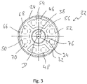
- ballast units 46 , 48 , 50 , 52 is provided in the interior space 26 of the soil cultivation roller 22 .
- the two ballast units 46, 48 and the two ballast units 50, 52 are diametrically opposite one another with respect to the roller axis of rotation D, so that the ballast units 46, 48, 50, 52 provide a center of mass lying on the roller axis of rotation D and in rotational operation the ballast units 46, 48, 50, 52 generated imbalances are avoided.
- Each of the ballast units 46, 48, 50, 52 comprises a ballast element 54 that is preferably cylindrically elongated in the direction of the roller axis of rotation D.
- the ballast elements 54 of the ballast units 46, 48, 50, 52 each have a cross-sectional contour in the manner of a segment of a circular ring and, in their entirety, form the roller axis of rotation D surrounding ring-like structure of ballast elements 54, in the circumferential direction between immediately adjacent ballast elements 54 in each case an intermediate space 56 is formed.
- Each of the ballast units 46, 48, 50, 52 has an elastic suspension arrangement 58 in association with its ballast element 54.
- the ballast elements 54 are carried or suspended in their two axial end regions 60, 62 on the carrier elements 30, 32 via these elastic suspension arrangements 58.
- Each suspension arrangement 58 assigned to a ballast element 54 of a respective ballast unit 46, 48, 50, 52 comprises a suspension unit 64, 66 assigned to each of the two axial end regions 60, 62 of the ballast elements 54.
- the ballast elements 54 are attached via the suspension units 64, 66 carried or suspended on the support elements 30, 32.
- each of the suspension units 64, 66 comprises two suspension elements 68, 70 made of elastic material, for example rubber material, which are arranged at a circumferential distance from one another.
- These suspension elements designed as blocks of material are firmly connected, for example by screwing, to the axial end regions 60, 62 of a respective associated ballast element 54 on the one hand and respective carrier parts 72, 74 on the other hand, which can also be firmly connected to the associated carrier elements 30, 32 on the other hand, for example by screwing.
- the ballast elements 54 of the ballast units 46, 48, 50, 52 are therefore fundamentally supported in the interior 26 of the soil tillage roller 22 in a non-rotatable manner.
- a substantially cylindrical inner housing 76 surrounding the roller axis of rotation D can be provided and connected to the carrier elements 30, 32, for example by welding, in order to radially outside of this inner housing 76 between this and the roller shell 24 to delimit a space 78 for receiving the ballast units 46, 48, 50, 52 and inside the inner housing 76 a space 80 for receiving the unbalanced shaft 34 with the unbalanced mass units 38 on it.
- ballast elements 54 are not visible from the outside, so that there are no requirements for the visual appearance and the field of vision of the operator sitting in the cabin 16 is not impaired.
- the ballast elements 54 can be made of inexpensive material, such as. B. concrete and / and steel are built.
- suspension elements can be used as suspension elements 68, 70, which are also used in a similar way to elastically suspend such a soil tillage roller 10 with respect to the roller frame 22. It should be noted that such a suspension in Figures 1 to 3 is not shown, but can be provided axially on both sides of the carrier elements 30, 32 or can be coupled to these carrier elements 30, 32 via respective rotary decoupling bearings.
- ballast elements 54 of the ballast units 46, 48, 50, 52 in 3 shown intermediate space 56 there is no risk that when a relative movement of the ballast elements 54 occurs with respect to the roll shell 24, ballast elements 54 directly adjacent to one another will strike against one another.
- each vibration system provided by such a ballast unit 46, 48, 50, 52
Landscapes
- Engineering & Computer Science (AREA)
- Structural Engineering (AREA)
- Civil Engineering (AREA)
- Life Sciences & Earth Sciences (AREA)
- Architecture (AREA)
- Environmental & Geological Engineering (AREA)
- General Life Sciences & Earth Sciences (AREA)
- Mining & Mineral Resources (AREA)
- Paleontology (AREA)
- Soil Sciences (AREA)
- General Engineering & Computer Science (AREA)
- Agronomy & Crop Science (AREA)
- Mechanical Engineering (AREA)
- Road Paving Machines (AREA)
- Soil Working Implements (AREA)
Claims (13)
- Rouleau de traitement du sol pour une machine de traitement du sol, en particulier un compacteur de sol, comprenant :- une enveloppe du rouleau (24) s'étendant longitudinalement dans une direction d'un axe de rotation de rouleau (D) et délimitant un intérieur de rouleau (26),- au moins une unité de ballast (46, 48, 50, 52) disposée dans l'intérieur du rouleau (26), dans laquelle chaque unité de ballast (46, 48, 50, 52) comprend au moins un élément de ballast (54) supporté par rapport à l'enveloppe du rouleau (24) au moyen d'un agencement de suspension élastique (58),caractérisé en ce que
ledit au moins un élément de ballast (54) est couplé de manière permanente à l'enveloppe du rouleau (24) par l'agencement de suspension (58) et est mobile par rapport à l'enveloppe du rouleau dans la direction radiale, la direction axiale et la direction circonférentielle. - Rouleau de traitement du sol selon la revendication 1,
caractérisé en ce que
une pluralité d'unités de ballast (46, 48, 50, 52) disposées en série dans la direction circonférentielle est prévue à l'intérieur du rouleau (26), dans lequel chaque unité de ballast (46, 48, 50, 52) comprend au moins un élément de ballast supporté par rapport à l'enveloppe du rouleau (24) au moyen de l'agencement de suspension élastique (58). - Rouleau de traitement du sol selon la revendication 1 ou 2,
caractérisé en ce que
pour au moins une, de préférence chaque unité de ballast (46, 48, 50, 52), ledit au moins un élément de ballast (54) s'étend longitudinalement dans la direction de l'axe de rotation (D) du rouleau et/ou présente un contour de section transversale en forme de segment d'anneau circulaire. - Rouleau de traitement du sol selon la revendication 1, 2 ou 3,
caractérisé en ce que
pour au moins une, de préférence chaque unité de ballast (46, 48, 50, 52), l'agencement de suspension (58) à chaque extrémité axiale (60, 62) dudit au moins un élément de ballast (54) comprend une unité de suspension (64, 66) fixe par rapport audit au moins un élément de ballast (54) et/ou par rapport à l'enveloppe du rouleau (24). - Rouleau de traitement du sol selon la revendication 4,
caractérisé en ce qu'au moins une, de préférence les deux unités de suspension (64, 66) comprennent au moins un élément de suspension (68, 70) fixé par rapport audit au moins un élément de ballast (54) et à l'enveloppe du rouleau (24). - Rouleau de traitement du sol selon la revendication 5,
caractérisé en ce qu'au moins une, de préférence les deux unités de suspension (64, 66) comprennent une pluralité d'éléments de suspension (68, 70). - Rouleau de traitement du sol selon la revendication 5 ou 6,
caractérisé en ce qu'au moins un, de préférence chaque élément de suspension (68, 70) est construit en utilisant un matériau élastomère, de préférence un matériau en caoutchouc. - Rouleau de traitement du sol selon l'une des revendications 4 à 7, caractérisé en ce que
des éléments de support (30, 32) sont prévus à distance axiale les uns des autres sur l'enveloppe du rouleau (24), et en ce que pour au moins une, de préférence chaque unité de ballast (46, 48, 50, 52), chacune des deux unités de suspension (64, 66) est fixée par rapport à l'enveloppe du rouleau (24) par l'intermédiaire de l'un des éléments de support (30, 32). - Rouleau de traitement du sol selon l'une des revendications précédentes,
caractérisé en ce qu'un dispositif de masse de balourd (36) est muni d'au moins une unité de masse de balourd (38), disposé à l'intérieur du rouleau (26) et pouvant tourner autour d'un axe de balourd (U). - Rouleau de traitement du sol selon la revendication 9,
caractérisé en ce que
ledit au moins une unité de masse de balourd (38) comprend un arbre de balourd (34), pouvant tourner autour de l'axe de balourd (U), et au moins une masse de balourd (40, 42) supportée sur l'arbre de balourd (34) et ayant un centre de masse excentré par rapport à l'axe de balourd (U). - Rouleau de traitement du sol selon la revendication 8 et la revendication 10,
caractérisé en ce que
l'arbre de balourd (34) est supporté de manière rotative sur les éléments de support (30, 32). - Rouleau de traitement du sol selon l'une des revendications 9 à 11,
caractérisé en ce que
l'axe de balourd (U) correspond à l'axe longitudinal du rouleau (D), et/ou le dispositif de masse de balourd (36) comprend un entraînement à balourd (44) associé audit au moins une unité de masse de balourd (38). - Machine de traitement du sol, notamment compacteur de sol, comprenant au moins un rouleau de traitement du sol (22) selon l'une des revendications précédentes.
Applications Claiming Priority (1)
| Application Number | Priority Date | Filing Date | Title |
|---|---|---|---|
| DE102019132917.5A DE102019132917A1 (de) | 2019-12-04 | 2019-12-04 | Bodenbearbeitungswalze |
Publications (2)
| Publication Number | Publication Date |
|---|---|
| EP3832015A1 EP3832015A1 (fr) | 2021-06-09 |
| EP3832015B1 true EP3832015B1 (fr) | 2023-03-15 |
Family
ID=73059504
Family Applications (1)
| Application Number | Title | Priority Date | Filing Date |
|---|---|---|---|
| EP20205347.6A Active EP3832015B1 (fr) | 2019-12-04 | 2020-11-03 | Rouleau compacteur de sol |
Country Status (4)
| Country | Link |
|---|---|
| US (1) | US11542669B2 (fr) |
| EP (1) | EP3832015B1 (fr) |
| CN (2) | CN112900201B (fr) |
| DE (1) | DE102019132917A1 (fr) |
Families Citing this family (3)
| Publication number | Priority date | Publication date | Assignee | Title |
|---|---|---|---|---|
| DE102019132917A1 (de) * | 2019-12-04 | 2021-06-10 | Hamm Ag | Bodenbearbeitungswalze |
| CN113585011A (zh) * | 2021-06-18 | 2021-11-02 | 徐工集团工程机械股份有限公司道路机械分公司 | 一种压路机振动轮 |
| CN119372983B (zh) * | 2024-12-27 | 2025-03-14 | 福建第一公路工程集团有限公司 | 一种道路建设用沥青铺路机 |
Family Cites Families (16)
| Publication number | Priority date | Publication date | Assignee | Title |
|---|---|---|---|---|
| FR5327E (fr) * | 1904-04-20 | 1906-03-06 | Jules Auguste Vinsonneau | Rouleau cylindreur à charge amovible variable pour routes et chaussées empierrées |
| EP0636746B1 (fr) * | 1993-07-27 | 1999-11-03 | Caterpillar Paving Products Inc. | Compacteur vibrant avec un cadre accordé |
| US6095717A (en) * | 1999-04-23 | 2000-08-01 | Al-Jon | Compaction wheel having replaceable cleats |
| EP2558649B1 (fr) * | 2010-04-16 | 2014-11-19 | Ammann Schweiz AG | Agencement pour fournir une force de pression pulsée |
| CN102337718B (zh) * | 2011-07-20 | 2013-07-31 | 屠卫东 | 一种振动压路机激振器结构 |
| CN102852075B (zh) * | 2012-02-23 | 2015-12-02 | 江苏大学 | 一种振动压路机液体无级调幅激振器 |
| US10106936B2 (en) * | 2014-12-09 | 2018-10-23 | Volvo Construction Equipment Ab | Vibration isolation for compactor |
| DE102014226373A1 (de) * | 2014-12-18 | 2016-06-23 | Hamm Ag | Verdichtungsgerät, sowie Verfahren zum Verdichten von Böden |
| WO2017091912A1 (fr) * | 2015-12-03 | 2017-06-08 | Ammann Schweiz Ag | Agencement pour produire une force de compression pulsée |
| CN106702862A (zh) * | 2016-12-12 | 2017-05-24 | 徐工集团工程机械股份有限公司道路机械分公司 | 一种振动振荡自动转换机构及振动振荡压路机 |
| DE102016125927A1 (de) * | 2016-12-30 | 2018-07-05 | Hamm Ag | Verdichterwalze |
| CN106677033A (zh) * | 2017-03-07 | 2017-05-17 | 长安大学 | 一种仿生压路机钢轮及其操作方法 |
| US10072386B1 (en) * | 2017-05-11 | 2018-09-11 | Caterpillar Paving Products Inc. | Vibration system |
| JP6814726B2 (ja) * | 2017-12-22 | 2021-01-20 | 日立建機株式会社 | 転圧車両 |
| CN110512492B (zh) * | 2019-08-23 | 2021-09-24 | 嘉兴考普诺机械科技有限公司 | 一种可改变表面状态的压路机用碾轮结构 |
| DE102019132917A1 (de) * | 2019-12-04 | 2021-06-10 | Hamm Ag | Bodenbearbeitungswalze |
-
2019
- 2019-12-04 DE DE102019132917.5A patent/DE102019132917A1/de not_active Withdrawn
-
2020
- 2020-11-03 EP EP20205347.6A patent/EP3832015B1/fr active Active
- 2020-12-02 US US17/109,495 patent/US11542669B2/en active Active
- 2020-12-04 CN CN202011412346.4A patent/CN112900201B/zh active Active
- 2020-12-04 CN CN202022887581.9U patent/CN215482129U/zh not_active Withdrawn - After Issue
Also Published As
| Publication number | Publication date |
|---|---|
| CN112900201A (zh) | 2021-06-04 |
| EP3832015A1 (fr) | 2021-06-09 |
| CN215482129U (zh) | 2022-01-11 |
| DE102019132917A1 (de) | 2021-06-10 |
| CN112900201B (zh) | 2023-01-31 |
| US11542669B2 (en) | 2023-01-03 |
| US20210172127A1 (en) | 2021-06-10 |
Similar Documents
| Publication | Publication Date | Title |
|---|---|---|
| EP3832015B1 (fr) | Rouleau compacteur de sol | |
| DE102012201443A1 (de) | Verdichterwalze für einen Bodenverdichter | |
| EP3951057B1 (fr) | Système de rouleau de traitement du sol pour une machine de traitement du sol | |
| DE2630997A1 (de) | Traegheits-kegelbrecher | |
| EP2927661A2 (fr) | Actionneur | |
| EP2428788B1 (fr) | Dispositif de palier de pivotement d'un rotor devant être équilibré | |
| DE3428553C2 (fr) | ||
| EP2732100B1 (fr) | Excitateur à balourd pour compacteur de sol | |
| DE2710708C3 (de) | Lagerung für Walzkörper bei Verdichtungswalzen | |
| EP3342931B1 (fr) | Cylindre compacteur | |
| EP2781269A1 (fr) | Générateur de vibrations, notamment pour une machine de construction | |
| EP3670746B1 (fr) | Rouleau de traitement du sol | |
| EP3450631B1 (fr) | Vibreur en profondeur avec une masse non équilibrée réglable | |
| EP4230796B1 (fr) | Rouleau compresseur pour un compacteur de sol | |
| EP3722506A1 (fr) | Engin de compactage de sol | |
| EP0411450B1 (fr) | Dispositif d'appui pour le boîtier du différentiel d'un véhicule | |
| DE10260904A1 (de) | Vorrichtung mit einem sich drehenden Element im Umfeld einer Kolbenmaschine, insbesondere eine elektromagnetisch betätigte Reibscheibenkupplung, eine Spannrolle oder ein Schwingungsdämpfer | |
| EP2762314B1 (fr) | Cylindre rotatif | |
| DE583200C (de) | Schuettelsieb | |
| DE2205569C2 (de) | Schrämmwalze zum Lösen von Mineralien | |
| EP3839145A1 (fr) | Système de balourd | |
| AT228824B (de) | Vibrationswalze | |
| DE2060867C3 (de) | Kreisel. _ | |
| DE2006466C3 (de) | Vibrationshandschleifgerät für Kreis- und Geradschliff | |
| DE2324488A1 (de) | Stuetzeinheit eines vertikalrotors |
Legal Events
| Date | Code | Title | Description |
|---|---|---|---|
| PUAI | Public reference made under article 153(3) epc to a published international application that has entered the european phase |
Free format text: ORIGINAL CODE: 0009012 |
|
| STAA | Information on the status of an ep patent application or granted ep patent |
Free format text: STATUS: REQUEST FOR EXAMINATION WAS MADE |
|
| 17P | Request for examination filed |
Effective date: 20201103 |
|
| AK | Designated contracting states |
Kind code of ref document: A1 Designated state(s): AL AT BE BG CH CY CZ DE DK EE ES FI FR GB GR HR HU IE IS IT LI LT LU LV MC MK MT NL NO PL PT RO RS SE SI SK SM TR |
|
| GRAP | Despatch of communication of intention to grant a patent |
Free format text: ORIGINAL CODE: EPIDOSNIGR1 |
|
| STAA | Information on the status of an ep patent application or granted ep patent |
Free format text: STATUS: GRANT OF PATENT IS INTENDED |
|
| INTG | Intention to grant announced |
Effective date: 20230102 |
|
| GRAS | Grant fee paid |
Free format text: ORIGINAL CODE: EPIDOSNIGR3 |
|
| GRAA | (expected) grant |
Free format text: ORIGINAL CODE: 0009210 |
|
| STAA | Information on the status of an ep patent application or granted ep patent |
Free format text: STATUS: THE PATENT HAS BEEN GRANTED |
|
| AK | Designated contracting states |
Kind code of ref document: B1 Designated state(s): AL AT BE BG CH CY CZ DE DK EE ES FI FR GB GR HR HU IE IS IT LI LT LU LV MC MK MT NL NO PL PT RO RS SE SI SK SM TR |
|
| REG | Reference to a national code |
Ref country code: CH Ref legal event code: EP Ref country code: GB Ref legal event code: FG4D Free format text: NOT ENGLISH |
|
| REG | Reference to a national code |
Ref country code: DE Ref legal event code: R096 Ref document number: 502020002744 Country of ref document: DE |
|
| REG | Reference to a national code |
Ref country code: IE Ref legal event code: FG4D Free format text: LANGUAGE OF EP DOCUMENT: GERMAN |
|
| REG | Reference to a national code |
Ref country code: AT Ref legal event code: REF Ref document number: 1554069 Country of ref document: AT Kind code of ref document: T Effective date: 20230415 |
|
| REG | Reference to a national code |
Ref country code: SE Ref legal event code: TRGR |
|
| REG | Reference to a national code |
Ref country code: LT Ref legal event code: MG9D |
|
| REG | Reference to a national code |
Ref country code: NL Ref legal event code: MP Effective date: 20230315 |
|
| PG25 | Lapsed in a contracting state [announced via postgrant information from national office to epo] |
Ref country code: RS Free format text: LAPSE BECAUSE OF FAILURE TO SUBMIT A TRANSLATION OF THE DESCRIPTION OR TO PAY THE FEE WITHIN THE PRESCRIBED TIME-LIMIT Effective date: 20230315 Ref country code: NO Free format text: LAPSE BECAUSE OF FAILURE TO SUBMIT A TRANSLATION OF THE DESCRIPTION OR TO PAY THE FEE WITHIN THE PRESCRIBED TIME-LIMIT Effective date: 20230615 Ref country code: LV Free format text: LAPSE BECAUSE OF FAILURE TO SUBMIT A TRANSLATION OF THE DESCRIPTION OR TO PAY THE FEE WITHIN THE PRESCRIBED TIME-LIMIT Effective date: 20230315 Ref country code: LT Free format text: LAPSE BECAUSE OF FAILURE TO SUBMIT A TRANSLATION OF THE DESCRIPTION OR TO PAY THE FEE WITHIN THE PRESCRIBED TIME-LIMIT Effective date: 20230315 Ref country code: HR Free format text: LAPSE BECAUSE OF FAILURE TO SUBMIT A TRANSLATION OF THE DESCRIPTION OR TO PAY THE FEE WITHIN THE PRESCRIBED TIME-LIMIT Effective date: 20230315 |
|
| PG25 | Lapsed in a contracting state [announced via postgrant information from national office to epo] |
Ref country code: NL Free format text: LAPSE BECAUSE OF FAILURE TO SUBMIT A TRANSLATION OF THE DESCRIPTION OR TO PAY THE FEE WITHIN THE PRESCRIBED TIME-LIMIT Effective date: 20230315 Ref country code: GR Free format text: LAPSE BECAUSE OF FAILURE TO SUBMIT A TRANSLATION OF THE DESCRIPTION OR TO PAY THE FEE WITHIN THE PRESCRIBED TIME-LIMIT Effective date: 20230616 Ref country code: FI Free format text: LAPSE BECAUSE OF FAILURE TO SUBMIT A TRANSLATION OF THE DESCRIPTION OR TO PAY THE FEE WITHIN THE PRESCRIBED TIME-LIMIT Effective date: 20230315 |
|
| PG25 | Lapsed in a contracting state [announced via postgrant information from national office to epo] |
Ref country code: SM Free format text: LAPSE BECAUSE OF FAILURE TO SUBMIT A TRANSLATION OF THE DESCRIPTION OR TO PAY THE FEE WITHIN THE PRESCRIBED TIME-LIMIT Effective date: 20230315 Ref country code: RO Free format text: LAPSE BECAUSE OF FAILURE TO SUBMIT A TRANSLATION OF THE DESCRIPTION OR TO PAY THE FEE WITHIN THE PRESCRIBED TIME-LIMIT Effective date: 20230315 Ref country code: PT Free format text: LAPSE BECAUSE OF FAILURE TO SUBMIT A TRANSLATION OF THE DESCRIPTION OR TO PAY THE FEE WITHIN THE PRESCRIBED TIME-LIMIT Effective date: 20230717 Ref country code: ES Free format text: LAPSE BECAUSE OF FAILURE TO SUBMIT A TRANSLATION OF THE DESCRIPTION OR TO PAY THE FEE WITHIN THE PRESCRIBED TIME-LIMIT Effective date: 20230315 Ref country code: EE Free format text: LAPSE BECAUSE OF FAILURE TO SUBMIT A TRANSLATION OF THE DESCRIPTION OR TO PAY THE FEE WITHIN THE PRESCRIBED TIME-LIMIT Effective date: 20230315 |
|
| PG25 | Lapsed in a contracting state [announced via postgrant information from national office to epo] |
Ref country code: SK Free format text: LAPSE BECAUSE OF FAILURE TO SUBMIT A TRANSLATION OF THE DESCRIPTION OR TO PAY THE FEE WITHIN THE PRESCRIBED TIME-LIMIT Effective date: 20230315 Ref country code: PL Free format text: LAPSE BECAUSE OF FAILURE TO SUBMIT A TRANSLATION OF THE DESCRIPTION OR TO PAY THE FEE WITHIN THE PRESCRIBED TIME-LIMIT Effective date: 20230315 Ref country code: IS Free format text: LAPSE BECAUSE OF FAILURE TO SUBMIT A TRANSLATION OF THE DESCRIPTION OR TO PAY THE FEE WITHIN THE PRESCRIBED TIME-LIMIT Effective date: 20230715 |
|
| REG | Reference to a national code |
Ref country code: DE Ref legal event code: R097 Ref document number: 502020002744 Country of ref document: DE |
|
| PLBE | No opposition filed within time limit |
Free format text: ORIGINAL CODE: 0009261 |
|
| STAA | Information on the status of an ep patent application or granted ep patent |
Free format text: STATUS: NO OPPOSITION FILED WITHIN TIME LIMIT |
|
| PG25 | Lapsed in a contracting state [announced via postgrant information from national office to epo] |
Ref country code: SI Free format text: LAPSE BECAUSE OF FAILURE TO SUBMIT A TRANSLATION OF THE DESCRIPTION OR TO PAY THE FEE WITHIN THE PRESCRIBED TIME-LIMIT Effective date: 20230315 Ref country code: DK Free format text: LAPSE BECAUSE OF FAILURE TO SUBMIT A TRANSLATION OF THE DESCRIPTION OR TO PAY THE FEE WITHIN THE PRESCRIBED TIME-LIMIT Effective date: 20230315 |
|
| 26N | No opposition filed |
Effective date: 20231218 |
|
| PG25 | Lapsed in a contracting state [announced via postgrant information from national office to epo] |
Ref country code: IT Free format text: LAPSE BECAUSE OF FAILURE TO SUBMIT A TRANSLATION OF THE DESCRIPTION OR TO PAY THE FEE WITHIN THE PRESCRIBED TIME-LIMIT Effective date: 20230315 |
|
| REG | Reference to a national code |
Ref country code: CH Ref legal event code: PL |
|
| PG25 | Lapsed in a contracting state [announced via postgrant information from national office to epo] |
Ref country code: MC Free format text: LAPSE BECAUSE OF FAILURE TO SUBMIT A TRANSLATION OF THE DESCRIPTION OR TO PAY THE FEE WITHIN THE PRESCRIBED TIME-LIMIT Effective date: 20230315 |
|
| PG25 | Lapsed in a contracting state [announced via postgrant information from national office to epo] |
Ref country code: LU Free format text: LAPSE BECAUSE OF NON-PAYMENT OF DUE FEES Effective date: 20231103 |
|
| PG25 | Lapsed in a contracting state [announced via postgrant information from national office to epo] |
Ref country code: CH Free format text: LAPSE BECAUSE OF NON-PAYMENT OF DUE FEES Effective date: 20231130 |
|
| PG25 | Lapsed in a contracting state [announced via postgrant information from national office to epo] |
Ref country code: MC Free format text: LAPSE BECAUSE OF FAILURE TO SUBMIT A TRANSLATION OF THE DESCRIPTION OR TO PAY THE FEE WITHIN THE PRESCRIBED TIME-LIMIT Effective date: 20230315 Ref country code: LU Free format text: LAPSE BECAUSE OF NON-PAYMENT OF DUE FEES Effective date: 20231103 Ref country code: CH Free format text: LAPSE BECAUSE OF NON-PAYMENT OF DUE FEES Effective date: 20231130 |
|
| REG | Reference to a national code |
Ref country code: BE Ref legal event code: MM Effective date: 20231130 |
|
| REG | Reference to a national code |
Ref country code: IE Ref legal event code: MM4A |
|
| PG25 | Lapsed in a contracting state [announced via postgrant information from national office to epo] |
Ref country code: IE Free format text: LAPSE BECAUSE OF NON-PAYMENT OF DUE FEES Effective date: 20231103 |
|
| PG25 | Lapsed in a contracting state [announced via postgrant information from national office to epo] |
Ref country code: BE Free format text: LAPSE BECAUSE OF NON-PAYMENT OF DUE FEES Effective date: 20231130 |
|
| PG25 | Lapsed in a contracting state [announced via postgrant information from national office to epo] |
Ref country code: FR Free format text: LAPSE BECAUSE OF NON-PAYMENT OF DUE FEES Effective date: 20231130 |
|
| PG25 | Lapsed in a contracting state [announced via postgrant information from national office to epo] |
Ref country code: IE Free format text: LAPSE BECAUSE OF NON-PAYMENT OF DUE FEES Effective date: 20231103 Ref country code: FR Free format text: LAPSE BECAUSE OF NON-PAYMENT OF DUE FEES Effective date: 20231130 Ref country code: BE Free format text: LAPSE BECAUSE OF NON-PAYMENT OF DUE FEES Effective date: 20231130 |
|
| PG25 | Lapsed in a contracting state [announced via postgrant information from national office to epo] |
Ref country code: BG Free format text: LAPSE BECAUSE OF FAILURE TO SUBMIT A TRANSLATION OF THE DESCRIPTION OR TO PAY THE FEE WITHIN THE PRESCRIBED TIME-LIMIT Effective date: 20230315 |
|
| PG25 | Lapsed in a contracting state [announced via postgrant information from national office to epo] |
Ref country code: BG Free format text: LAPSE BECAUSE OF FAILURE TO SUBMIT A TRANSLATION OF THE DESCRIPTION OR TO PAY THE FEE WITHIN THE PRESCRIBED TIME-LIMIT Effective date: 20230315 |
|
| GBPC | Gb: european patent ceased through non-payment of renewal fee |
Effective date: 20241103 |
|
| PG25 | Lapsed in a contracting state [announced via postgrant information from national office to epo] |
Ref country code: CY Free format text: LAPSE BECAUSE OF FAILURE TO SUBMIT A TRANSLATION OF THE DESCRIPTION OR TO PAY THE FEE WITHIN THE PRESCRIBED TIME-LIMIT; INVALID AB INITIO Effective date: 20201103 |
|
| PG25 | Lapsed in a contracting state [announced via postgrant information from national office to epo] |
Ref country code: HU Free format text: LAPSE BECAUSE OF FAILURE TO SUBMIT A TRANSLATION OF THE DESCRIPTION OR TO PAY THE FEE WITHIN THE PRESCRIBED TIME-LIMIT; INVALID AB INITIO Effective date: 20201103 |
|
| PG25 | Lapsed in a contracting state [announced via postgrant information from national office to epo] |
Ref country code: GB Free format text: LAPSE BECAUSE OF NON-PAYMENT OF DUE FEES Effective date: 20241103 |
|
| PG25 | Lapsed in a contracting state [announced via postgrant information from national office to epo] |
Ref country code: TR Free format text: LAPSE BECAUSE OF FAILURE TO SUBMIT A TRANSLATION OF THE DESCRIPTION OR TO PAY THE FEE WITHIN THE PRESCRIBED TIME-LIMIT Effective date: 20230315 |
|
| PGFP | Annual fee paid to national office [announced via postgrant information from national office to epo] |
Ref country code: DE Payment date: 20251119 Year of fee payment: 6 |
|
| PGFP | Annual fee paid to national office [announced via postgrant information from national office to epo] |
Ref country code: AT Payment date: 20260113 Year of fee payment: 5 |
|
| PGFP | Annual fee paid to national office [announced via postgrant information from national office to epo] |
Ref country code: SE Payment date: 20251119 Year of fee payment: 6 |
|
| PGFP | Annual fee paid to national office [announced via postgrant information from national office to epo] |
Ref country code: CZ Payment date: 20251029 Year of fee payment: 6 |