EP3832369B1 - Microscope à fluorescence par feuille lumineuse - Google Patents
Microscope à fluorescence par feuille lumineuse Download PDFInfo
- Publication number
- EP3832369B1 EP3832369B1 EP19213913.7A EP19213913A EP3832369B1 EP 3832369 B1 EP3832369 B1 EP 3832369B1 EP 19213913 A EP19213913 A EP 19213913A EP 3832369 B1 EP3832369 B1 EP 3832369B1
- Authority
- EP
- European Patent Office
- Prior art keywords
- light
- manipulation
- specimen
- excitation
- fluorescence microscope
- Prior art date
- Legal status (The legal status is an assumption and is not a legal conclusion. Google has not performed a legal analysis and makes no representation as to the accuracy of the status listed.)
- Active
Links
Images


Classifications
-
- G—PHYSICS
- G02—OPTICS
- G02B—OPTICAL ELEMENTS, SYSTEMS OR APPARATUS
- G02B21/00—Microscopes
- G02B21/0004—Microscopes specially adapted for specific applications
- G02B21/002—Scanning microscopes
- G02B21/0024—Confocal scanning microscopes (CSOMs) or confocal "macroscopes"; Accessories which are not restricted to use with CSOMs, e.g. sample holders
- G02B21/0032—Optical details of illumination, e.g. light-sources, pinholes, beam splitters, slits, fibers
-
- G—PHYSICS
- G01—MEASURING; TESTING
- G01N—INVESTIGATING OR ANALYSING MATERIALS BY DETERMINING THEIR CHEMICAL OR PHYSICAL PROPERTIES
- G01N21/00—Investigating or analysing materials by the use of optical means, i.e. using sub-millimetre waves, infrared, visible or ultraviolet light
- G01N21/62—Systems in which the material investigated is excited whereby it emits light or causes a change in wavelength of the incident light
- G01N21/63—Systems in which the material investigated is excited whereby it emits light or causes a change in wavelength of the incident light optically excited
- G01N21/64—Fluorescence; Phosphorescence
- G01N21/645—Specially adapted constructive features of fluorimeters
- G01N21/6456—Spatial resolved fluorescence measurements; Imaging
- G01N21/6458—Fluorescence microscopy
-
- G—PHYSICS
- G01—MEASURING; TESTING
- G01N—INVESTIGATING OR ANALYSING MATERIALS BY DETERMINING THEIR CHEMICAL OR PHYSICAL PROPERTIES
- G01N21/00—Investigating or analysing materials by the use of optical means, i.e. using sub-millimetre waves, infrared, visible or ultraviolet light
- G01N21/62—Systems in which the material investigated is excited whereby it emits light or causes a change in wavelength of the incident light
- G01N21/63—Systems in which the material investigated is excited whereby it emits light or causes a change in wavelength of the incident light optically excited
- G01N21/64—Fluorescence; Phosphorescence
- G01N21/645—Specially adapted constructive features of fluorimeters
- G01N21/648—Specially adapted constructive features of fluorimeters using evanescent coupling or surface plasmon coupling for the excitation of fluorescence
-
- G—PHYSICS
- G02—OPTICS
- G02B—OPTICAL ELEMENTS, SYSTEMS OR APPARATUS
- G02B21/00—Microscopes
- G02B21/0004—Microscopes specially adapted for specific applications
- G02B21/002—Scanning microscopes
- G02B21/0024—Confocal scanning microscopes (CSOMs) or confocal "macroscopes"; Accessories which are not restricted to use with CSOMs, e.g. sample holders
- G02B21/0036—Scanning details, e.g. scanning stages
- G02B21/0048—Scanning details, e.g. scanning stages scanning mirrors, e.g. rotating or galvanomirrors, MEMS mirrors
-
- G—PHYSICS
- G02—OPTICS
- G02B—OPTICAL ELEMENTS, SYSTEMS OR APPARATUS
- G02B21/00—Microscopes
- G02B21/0004—Microscopes specially adapted for specific applications
- G02B21/002—Scanning microscopes
- G02B21/0024—Confocal scanning microscopes (CSOMs) or confocal "macroscopes"; Accessories which are not restricted to use with CSOMs, e.g. sample holders
- G02B21/0052—Optical details of the image generation
- G02B21/0076—Optical details of the image generation arrangements using fluorescence or luminescence
-
- G—PHYSICS
- G02—OPTICS
- G02B—OPTICAL ELEMENTS, SYSTEMS OR APPARATUS
- G02B21/00—Microscopes
- G02B21/06—Means for illuminating specimens
-
- G—PHYSICS
- G02—OPTICS
- G02B—OPTICAL ELEMENTS, SYSTEMS OR APPARATUS
- G02B21/00—Microscopes
- G02B21/16—Microscopes adapted for ultraviolet illumination ; Fluorescence microscopes
-
- G—PHYSICS
- G02—OPTICS
- G02B—OPTICAL ELEMENTS, SYSTEMS OR APPARATUS
- G02B21/00—Microscopes
- G02B21/32—Micromanipulators structurally combined with microscopes
-
- G—PHYSICS
- G02—OPTICS
- G02B—OPTICAL ELEMENTS, SYSTEMS OR APPARATUS
- G02B21/00—Microscopes
- G02B21/36—Microscopes arranged for photographic purposes or projection purposes or digital imaging or video purposes including associated control and data processing arrangements
- G02B21/365—Control or image processing arrangements for digital or video microscopes
- G02B21/367—Control or image processing arrangements for digital or video microscopes providing an output produced by processing a plurality of individual source images, e.g. image tiling, montage, composite images, depth sectioning, image comparison
-
- G—PHYSICS
- G01—MEASURING; TESTING
- G01N—INVESTIGATING OR ANALYSING MATERIALS BY DETERMINING THEIR CHEMICAL OR PHYSICAL PROPERTIES
- G01N21/00—Investigating or analysing materials by the use of optical means, i.e. using sub-millimetre waves, infrared, visible or ultraviolet light
- G01N21/62—Systems in which the material investigated is excited whereby it emits light or causes a change in wavelength of the incident light
- G01N21/63—Systems in which the material investigated is excited whereby it emits light or causes a change in wavelength of the incident light optically excited
- G01N21/64—Fluorescence; Phosphorescence
- G01N21/645—Specially adapted constructive features of fluorimeters
- G01N2021/6463—Optics
Definitions
- the present invention relates to a light sheet fluorescence microscope, comprising a light source device configured to emit excitation light suitable for inducing fluorescent light emitted from a specimen, a detector device configured to detect the fluorescent light from the specimen, and an optical system configured to illuminate the specimen with a light sheet formed from the excitation light and to guide the fluorescent light from the illuminated specimen to the detector device, wherein the optical system comprises an objective facing the specimen, the objective being configured to collect the fluorescent light emitted from the specimen. Further, the invention relates to a method for imaging a specimen by means of a light sheet fluorescence microscope.
- Light sheet fluorescence microscopy is a technique in which a thin slice of a specimen is illuminated with a specific excitation light distribution which is focused only in one direction for example by using a cylindrical lens. Another illumination method uses a collimated light beam which is scanned in one direction to create a light distribution forming a light sheet. Due to the fact that only a portion of the specimen is illuminated which is actually observed, light sheet fluorescence microscopy reduces photo damage and stress induced on a living specimen. Furthermore, in contrast to confocal laser scanning microscopy where the specimen is scanned point by point, light sheet fluorescence microscopy is a wide field technique which allows to generate a three-dimensional stack of images based on optical sections through different planes of the specimen.
- a light sheet fluorescence microscope comprises separate objectives for illuminating the specimen with the light sheet and for observing the illuminated object plane.
- light sheet methods have been developed which use only one objective both for illumination and detection. For example, by illuminating a small spot of an aperture of a high NA objective, a tilted light sheet may be generated.
- OPM oblique plane microscopy
- SCAPE swept confocally aligned planar excitation microscopy
- a specimen may be photomanipulated during or before actual imaging by e.g. heating, bleaching, photoactivating, photodeactivating etc.
- a laser beam of suitable intensity and wavelength may be directed to the specimen.
- a system capable of photomanipulating a specimen is e.g. disclosed in DE 10 2007 047 464 A1 .
- This system comprises two objectives for illuminating the specimen and for detecting fluorescent light induced in the specimen.
- In the optical detection path means for directing manipulation light onto the specimen are provided.
- this known system is not flexible enough in terms of applicability. For example, the system is not applicable to OPM or SCAPE configurations.
- Document EP 1 617 255 A1 discloses a microscope comprising an objective through which fluorescent light emitted from a specimen is collected.
- the microscope further comprises two illumination channels through which two parallel illumination beams are directed onto the sample from opposite lateral directions.
- the illumination channels are arranged outside the objective.
- Document DE 10 2013 213 781 A1 discloses a light sheet fluorescence microscope including an optical system which is configured to illuminate a specimen with a light sheet formed from excitation light.
- the optical system is further configured to illuminate the specimen with manipulation light. Both, the excitation light and the manipulation light are directed through an illumination objective onto the specimen. An entrance pupil of the illumination objective is completely illuminated with the manipulation light.
- a detection objective is arranged which directs fluorescence light emerging from the specimen onto a detector.
- Document WO 2015/109323 A2 discloses a light sheet fluorescence microscope according to the preamble of claim 1.
- the microscope includes separate light sources for emitting illumination light and manipulation light. Both, the illumination light and the manipulation light are directed through a common objective lens into the specimen.
- a spatial light manipulator is provided outside the beam path of the illumination light and serves to direct the manipulation light onto a beam splitter which reflects the manipulation light into the objective lens.
- a similar configuration is disclosed in the document US 2016/327779 A1 .
- a light sheet fluorescence microscope comprises a light source device configured to emit excitation light suitable for inducing fluorescent light emitted from a specimen, a detector device configured to detect the fluorescent light from the specimen, and an optical system configured to illuminate the specimen with a light sheet formed from the excitation light and to guide the fluorescent light from the illuminated specimen to the detector device.
- the optical system comprises an objective facing the specimen, wherein the objective is configured to collect the fluorescent light emitted from the specimen.
- the optical system is further configured to direct the manipulation light through a spatially limited sub-area of an entrance pupil of the objective onto the specimen along a light propagation direction which is different from a light propagation direction of the light sheet.
- excitation light or illumination light is to be understood as light which is applied to the specimen in order to induce light emanating therefrom and being suitable to be detected for imaging the specimen.
- excitation or illumination light as defined herein directly refers to the imaging process.
- the illumination or excitation light may be light which excites the specimen to emit fluorescent light for generating an optical image which represents structural information of the illuminated specimen.
- manipulation light is to be understood as light which is applied to the specimen in order to manipulate the same by means of light in a way going beyond pure imaging.
- manipulation light may comprise light which is used for heating, cutting, photoactivating, photodeactivating, bleaching, triggering chemical reactions e.g.in the field of optogenetics, etc.
- the light sheet fluorescence microscope operates to partially illuminate the entrance pupil of the objective with manipulation light in order to photomanipulate the specimen along a direction as desired under the specific experimental circumstances.
- applying a partial pupil illumination allows a direction along which the manipulation light propagates into the specimen to be adjusted in a flexible manner by varying the sub-area of the entrance pupil onto which the manipulation light is directed.
- a region of interest within the object plane illuminated with the light sheet can be freely selected for photomanipulation according to the needs or preferences arising from the specific experimental setup.
- the light sheet fluorescence microscope is usable in a wide range of applications.
- photomanipulating the specimen through a dedicated sub-area of the entrance pupil allows the microscope to advantageously be used in OPM or SCAPE configurations without being restricted thereto.
- the optical system is configured to illuminate the specimen with the light sheet through the objective.
- the objective facing the specimen is commonly used for illuminating the specimen with excitation light and photomanipulating the same with manipulation light as well as for observing the illuminated plane.
- the spatially limited sub-area may be located offset from a center of the entrance pupil of the objective. By varying the offset distance from the pupil center, the propagation direction of the manipulation light can be easily adjusted as required in the specific experiment.
- the optical system may be preferably configured to direct the excitation light through another spatially limited sub-area of the entrance pupil onto the specimen, wherein this other sub-area is located offset from the sub-area through which the manipulation light is directed onto the specimen.
- This embodiment may be advantageously applied in OPM and SCAPE configurations.
- the light propagation direction of the manipulation light emanating from the objective towards the specimen has an angle relative to a direction opposite to a light propagation direction of the fluorescent light emitted by the specimen in an angular range from 0 to ⁇ 45°.
- the afore-mentioned angle may be set to zero, i.e. the manipulation light is irradiated onto the specimen in a direction directly opposite to the detection axis. This facilitates to photomanipulate the specimen accurately.
- the optical system comprises a scanning mirror device including at least one tilting mirror which is tiltable for reflecting the excitation light to move the light sheet as a whole through the specimen in a light sheet scanning direction transverse to the light propagation direction of the light sheet.
- the at least one scanning mirror is tiltable for reflecting both the excitation light and the manipulation light.
- the excitation light and the manipulation light can be commonly scanned through the specimen so that imaging and photomanipulating can be easily performed in a coordinated manner.
- the scanning mirror device may comprise a scan lens and one single tilting mirror which is located in a rear focal plane of the scanning lens.
- the scanning mirror device comprises two tilting mirrors located offset to each other along an optical axis of the optical system. This configuration allows that a scan lens can be dispensed with. Thus, using two tilting mirrors rather than one single mirror provides for an additional degree of freedom which can be utilized to freely adjust the (virtual) axis for tilting the exaction light.
- the scanning mirror device is provided with two tilting mirrors
- these mirrors can be easily controlled to switch between two tilting states, one of which being applied to illuminate the specimen with the excitation light and the other being applied for photomanipulation. Switching between illumination and photomanipulation can be rapidly performed by the scanning mirror device within several milliseconds which is of significant advantageous e.g. in cases in which fast processes shall be observed in a biological specimen.
- the at least one tilting mirror is tiltable for reflecting the fluorescent light collected by the objective towards the detector device.
- an optical shifting unit is provided which is configured to shift an incident position of the manipulation light on the at least one tiltable mirror for varying the light propagation direction of the manipulation light directed onto the specimen independently of the light propagation direction of the fluorescent light and/or independently of the light propagation direction of the light sheet. This renders the photomanipulation even more flexible in terms its positional relationship relative to the excitation light.
- the manipulation light may be directed to a site located outside the object plane which is illuminated with the light sheet
- the optical shifting unit may comprise at least one element reflecting or emitting the manipulation light, wherein this element is movable to shift the incident position of the manipulation light on the at least one tiltable mirror.
- the optical shifting unit may be formed by a dichroic mirror which may be used to couple the manipulation into the optical system.
- the light source device may be configured to emit the excitation light and the manipulation light along a common optical path into the optical system. This allows to use one single light source emitting both the excitation light and the manipulation light. Alternatively, a plurality of the light sources may be integrated in a common casing.
- the light source device comprises at least one excitation light source configured to emit the excitation light along at least one first optical path, and at least one manipulation light source configured to emit the manipulation light along at least one second optical path.
- the light source device further comprises a light shaping system having an optical input formed by the first and second optical paths and an optical output formed by the common optical path, wherein the light shaping system is configured to selectively shape at least one of the excitation light and the manipulation light.
- the light shaping system may comprise an input merging element configured to merge the first and second optical paths in a third optical path.
- the input merging element may be formed e.g. by a dichroic mirror.
- the light shaping system may further include a beam expander located in the third optical path.
- the beam expander may be used to shape both the excitation light and the manipulation light in a first step before further light shaping and/or scanning is applied, e.g. for dynamically creating the light sheet, shifting a focus of the manipulation light, displacing the excitation light and/or the manipulation light in directions transverse to the light propagation direction etc.
- the common optical path is formed by the third optical path.
- the light shaping system may comprise at least one light shaping element and a scanner which are located in the common optical path, wherein, in the excitation operating mode, the light shaping element is configured not to shape the excitation light and the scanner is configured to cause a scanning movement of the excitation light in a predetermined direction transverse to the light propagation direction of the excitation light for generating the light sheet.
- the light shaping element In the manipulation operating mode, the light shaping element is configured to shape the manipulation light and the scanner is configured to adjust a displacement of the manipulation light in the predetermined direction.
- a single (third) optical path is provided inside the light shaping system for taking effect on both the excitation light and the manipulation. Further, the light shaping system the light sheet is created dynamically, e.g. by rapidly scanning the collimated excitation light through the specimen.
- the light shaping system includes a splitting element located in the third optical path and configured to spatially separate the excitation light and the manipulation light from each other, wherein the excitation light propagates in a fourth optical path and the manipulation light propagates in a fifth optical path.
- the light shaping system further comprises an output merging element configured to merge the fourth and fifth optical paths in the common optical path.
- the light shaping system comprises an anamorphic optical element located in the fourth optical path, wherein the anamorphic optical element is configured to generate the light sheet from the excitation light.
- the light shaping system further comprises at least one light shaping element and/or a scanner located in the fifth optical path, wherein the light shaping element is configured to shape the manipulation light and the scanner is configured to adjust a displacement of the manipulation light in a predetermined direction.
- the light shaping system provides for two separate (fourth and fifth) optical paths in order take effect on the excitation light and the manipulation light, respectively. Further, the light sheet is created by means of optical beam shaping rather than by scanning.
- the light shaping element may comprise at least one of an electrically tunable lens, a deformable mirror, a digital mirror device, and a spatial light modulator.
- the light shaping element is configured to shift a focus of the manipulation light in the light propagation direction thereof.
- the light shaping element may be formed by an electrically tunable lens.
- a method for imaging the specimen by means of a light sheet fluorescence microscope comprising the following steps: emitting excitation light suitable for inducing fluorescent light emitted by the specimen; illuminating the specimen with a light sheet formed from the excitation light; collecting the fluorescent light from the illuminated specimen by means of an objective facing the specimen; and detecting the fluorescent light.
- the method further comprises the steps of: emitting manipulation light suitable for photomanipulating the specimen; and directing the manipulation light through a spatially limited sub-area of an entrance pupil of the objective onto the specimen along a light propagation direction which is different from a light propagation direction of the light sheet.
- a light sheet fluorescence microscope 100 according to an embodiment is illustrated in the diagram of Figure 1 , wherein only those components of the light sheet fluorescence microscope 100 are shown which are helpful for understanding the embodiment.
- the light sheet fluorescence microscope 100 comprises a light source device 102, a detector device 104 which may be formed by a CCD or CMOS camera suitable for wide field imaging, and an optical system generally designated by reference sign 106.
- the optical system 106 may comprise a plurality of optical elements, among which an objective 108 faces a specimen 110 which is to be imaged by the light sheet fluorescence microscope 100.
- the objective 108 may be used for both illumination and detection. Thus, it may be a common objective through which both fluorescence-stimulating illumination light and fluorescence light are guided. Accordingly, the light sheet fluorescence microscope 100 may be operated in SCAPE or OPM configuration. However, the invention shall not be restricted to such a configuration. In particular, the light sheet fluorescence microscope may also comprise two separate objectives for fluorescence-exciting illumination and detection, respectively.
- the light source device 102 is configured to emit excitation light E which is suitable to excite the specimen 110 to emit fluorescent light F which is to be detected by the detector device 104. As explained below in more detail with reference to Figures 6 and 7 , the light source device 102 may be configured to shape a light sheet LS from the excitation light E for illuminating only a thin slice of the specimen 110 at a given point in time. In the specific embodiment shown in Figure 1 , the light sheet LS illuminating the specimen 110 propagates in a direction which is oblique to the optical axis O of the optical system 106.
- the light sheet LS illuminating the specimen 110 is expanded in a direction parallel to the x-axis which is orthogonal to the propagation direction of the light sheet LS. Accordingly, the illumination plane formed by the light sheet LS is defined by two axes, one of which given by the light sheet propagation direction lying in the xz-plane and the other being the x-axis.
- the optical system 106 is configured to illuminate the specimen 110 with the light sheet LS formed from the excitation light E as well as to guide the fluorescent light F from the illuminated specimen 110 to the detector device 104.
- the optical system 106 comprises a first lens 112, a second lens 114, a scanning mirror device 116, a third lens 118, a fourth lens 120 and the objective 108 facing the specimen 110.
- Each of the lenses 112 and 120 serves as a tube lens, wherein the lens 118 is configured as a scan lens.
- the scanning mirror device 116 is formed by a single tilting mirror 122 which reflects the excitation light E passing the lenses 112, 114 through the lenses 118, 120 into the objective 108 for illuminating the specimen 110 with the light sheet LS.
- the tilting mirror 122 is movable around a tilt axis 124 which is oriented parallel to the x-axis.
- the tilting mirror 122 reflects the excitation light E in different directions resulting in a scanning movement of the light sheet LS within the specimen 110 in a direction parallel to the y-axis.
- the scanning mirror device 116 serves to move the light sheet LS as a whole through the specimen 110 in a light sheet scanning direction which is illustrated in Figure 1 by a double arrow A.
- the tilting mirror 122 is located in a rear, i.e. image-side focal plane of the scan lens 118.
- a tilting movement of the excitation light E on the tilting mirror 122 is converted into a parallel displacement of the excitation light E on an object side of the scan lens 118.
- the fluorescent light F induced by the excitation light E is collected by the objective 108 and propagates in a direction opposite to the propagation direction of the excitation light E through the optical system 106 up to the tube lens 112. Subsequently, the fluorescent light F passes a dichroic mirror 126 which is configured to selectively transmit both the fluorescent light F and the excitation light E. Accordingly, in the specific embodiment shown in Figure 1 , the dichroic mirror 126 is used as a beam splitter for separating the excitation light E and the fluorescent light F. Further, a mirror 148 is provided serving as an element for coupling the excitation light E into the optical system 106. Needless to say that the configuration formed by the mirrors 126, 148 for implementing the afore-mentioned light separation and coupling functions is to be understood merely as an example. Other configurations may be used as will become evident from further embodiments described later.
- the fluorescent light F After passing the dichroic mirror 126, the fluorescent light F propagates through an optical detection system formed by two objectives 127, 128 and a tube lens 130 towards the detector device 104. Between the objectives 127, 128, an intermediate image plane 132 is located in which an intermediate image of the plane illuminated with the light sheet LS is formed. This intermediate image is imaged onto the detector device 104.
- the optical path leading to the detector device 104 is oblique relative to the optical path between the objective 108 and the tube lens 112. This reflects the fact that in SCAPE or OPM configuration the light sheet LS is oblique relative to an object-side focal plane P1 of the objective 108. Correspondingly, a plane P2 conjugate to the focal plane P1 is oblique relative to the intermediate image plane 132.
- the optical system 106 of the light sheet fluorescence microscope 100 forms a so-called descanned configuration.
- a descanned configuration ensures that the illuminated plane within the specimen 110 is continuously detected by the stationary detector device 104 while the illuminated plane is scanned in y-direction through the specimen 110.
- both the excitation light E and the fluorescent light F pass through the objective 108.
- neither the excitation light E nor the fluorescent light F fully utilize the aperture of the objective 108.
- the excitation light E and the fluorescent light F pass the objective 108 through different portions thereof, these portions being eccentrically located on opposite sides of the optical axis O.
- the light source device 102 is further configured to emit manipulation light M which is suitable to photomanipulate the specimen 110.
- manipulation light M is suitable to photomanipulate the specimen 110.
- photomanipulating the specimen 110 is to be understood broadly as light application which is not exclusively related to imaging as for example heating, bleaching etc.
- the dichroic mirror 126 is used to introduce the manipulation light M into the optical system 106. Accordingly, the characteristic of the dichroic mirror 126 is selected such that the dichroic mirror 126 reflects both the manipulation light M and the excitation light E and transmits the fluorescent light F. Thus, in the present embodiment it is assumed that the manipulation light M has essentially the same wavelength as the excitation light E. In such a case, a single laser source may be used to generate both the excitation light E and the manipulation light M.
- the manipulation light M passes the tube lens 112 through a portion which is different from a portion through which the excitation light E propagates through the tube lens 112.
- the manipulation light M falls onto the tilting mirror 112 at an incident position which is different from the incident position of the excitation light E.
- the manipulation light M propagates towards the objective 108 in a direction which is different from the propagation direction of the excitation light E.
- the optical system 106 is configured to direct the manipulation light M into the specimen 110 along a light propagation direction which is different from the propagation direction of the light sheet LS formed from the excitation light E.
- the manipulation light M passes the objective 108 through a spatially limited sub-area of an entrance pupil EP of the objective 108.
- the light sheet fluorescence microscope 100 may comprise an optical shifting unit which is configured to shift the incident position of the manipulation light M on the tilting mirror 122.
- an optical shifting unit may be formed by the dichroic mirror 126.
- the dichroic mirror 126 may be configured to be movable along the propagation direction of the manipulating light M falling onto the dichroic mirror 126, i.e. according to the configuration of Figure 1 in a direction parallel to the z-axis.
- the portion of the tube lens 122, through which the manipulation light M passes is shifted perpendicular to the optical axis O.
- the incident position of the manipulation light M on the tilting mirror 122 changes by moving the dichroic mirror 126 resulting in a corresponding variation of the direction in which the manipulation light M propagates into the specimen 110.
- the propagation direction of the manipulation light M can be varied independently of the propagation directions of the excitation light E and the fluorescent light F.
- the propagation direction of the manipulation light M emanating from the objective 108 towards the specimen 110 can be varied in a wide range.
- the angle of the propagation direction of the manipulation light M relative to a direction opposite to the propagation direction of the fluorescent light F emitted by the specimen 110 may be varied in an angular range from 0 to ⁇ 45°.
- the light propagation directions explained herein refer to the principal rays of the corresponding light beams.
- Figure 2 shows a light sheet fluorescence microscope 100a which represents a modified embodiment of the configuration of Figure 1 .
- the modification compared to the light sheet fluorescence microscope 100 shown in Figure 1 relates to a light source device 202 replacing the light source device 102 shown in Figure 1 .
- the light source device 202 of the light sheet fluorescence microscope 100a shown in Figure 2 outputs the excitation light E and the manipulation light M along two separate optical paths which may lie parallel to each other. Accordingly, the light source device 202 is comprised of two separate light sources 240 and 242 which output the excitation light E and the manipulation light M, respectively.
- the light sheet fluorescence microscope 100a shown in Figure 2 comprises a single component e.g. in form of a dichroic mirror 244 for commonly introducing the excitation light E and the manipulation light M into the optical system 106.
- the dichroic mirror 244 is adapted to the light source device 202 such that both the excitation light E and the manipulation light M are reflected into the optical system 106.
- the characteristic of the dichroic mirror 244 of the light sheet fluorescence microscope 100a is adapted to transmit the fluorescent light F towards the detector device 104.
- the light sheet fluorescence microscope 100a of Figure 2 does not provide for a variation of the propagation direction of the manipulation light M independently of the propagation direction of the excitation light E.
- the dichroic mirror 126 of Figure 1 only acts on the manipulation light M
- the dichroic mirror 244 shown in Figure 2 reflects both the excitation light E and the manipulation light M.
- the positional relationship between the excitation light E and the manipulation light M is not changed by the dichroic mirror 244 even if the dichroic mirror 244 was moved in a direction perpendicular to the optical axis O of the optical system 106.
- the direction along which the specimen 110 is photomanipulated by the manipulation light M does not change in relation to the direction along which the excitation light E illuminates the specimen 110. Accordingly, at any given time t1, t2, t3, the corresponding principle ray of the manipulation light M intersects the corresponding principle ray of the excitation light E in the focal plane P1 of the objective 108.
- Figure 3 is a diagram showing a light sheet fluorescence microscope 100b representing a further embodiment.
- the light sheet fluorescence microscope 100b differs from the embodiments shown in Figures 1 and 2 mainly by a modified scanning mirror device 318.
- the light sheet fluorescence microscope 100b of Figure 3 comprises a light source device 302 emitting the excitation light E and the manipulation light M.
- the light sheet fluorescence microscope 100b further comprises an optical system 306 which includes a tube lens 305, the scanning mirror device 316, a further tube lens 308 and the objective 108.
- the excitation light E and the manipulation light M are coupled into the optical system 306 by means of a mirror 348.
- the fluorescent light F emitted from the specimen 110 propagates through the optical system 306 in a direction essentially opposite to the propagation direction of the excitation light E and the manipulation light M. After passing the tube lens 305, the fluorescent light F propagates through two objectives 327, 328 and a tube lens 330 to a detector device 304.
- the configuration of Figure 3 is advantageously modified in terms of the tilting operation of the scanning mirror device 316 which is applied to scan the light sheet LS as a whole in y-direction through the specimen 110.
- the single tilting mirror 122 is located in the rear focal plane of the scan lens 118 to ensure that the tilting movement of the excitation light E on the tilting mirror 122 is converted into a parallel displacement of the excitation light E on the object side of the scan lens 118.
- the light sheet fluorescence microscope 100b shown in Figure 3 is modified in such a way that a scan lens can be dispensed with.
- the scanning mirror device 316 comprises two tilting mirrors 332, 334 which are located offset to each other along the optical axis O of the optical system 306.
- Each of the tilting mirrors 332, 334 is movable around a tilt axis 336, 338 as shown in Figure 4 .
- the respective tilt axis 336, 338 is oriented parallel to the x-axis.
- the two tilting mirrors 332, 334 By using the two tilting mirrors 332, 334 instead of one single tilting mirror as provided in the configurations of Figures 1 and 2 , the intended parallel displacement of the excitation light E emanating from the scanning mirror device 316 can be achieved without providing a dedicated scan lens.
- the two tilting mirrors 332, 334 provide for an additional degree of freedom in terms of adjusting the tilting operation which results in a virtual tilt axis about which the excitation light E is tilted when operating the scanning mirror device 316.
- the axis for tilting the excitation light E is fixed (see tilt axis 124 in Figures 1 and 2 ).
- a virtual, i.e. non-physical tilt axis can be freely created as needed.
- this virtual tilt axis is located such that the intended parallel displacement of the excitation light E propagating towards the specimen 110 is achieved.
- two tilting states of the scanning mirror device 316 are illustrated, a difference between these two tilting states corresponding to a tilting angle ⁇ .
- the tilting angle ⁇ defines the amount of tilting about a virtual tilt axis V which is located on the image side of the first tilting mirror 332. Tilting the excitation light E in the amount of angle ⁇ about the virtual tilt axis V is converted into a parallel displacement d of the excitation light E on the object side of the second tilting mirror 334.
- the virtual tilt axis V is located in the rear, i.e. image-side focal plane of the objective 108 (or a plane conjugate thereto).
- Figure 3 does not illustrate the scanning movement of the manipulation light M achieved by operating the scanning mirror device 316 as explained above. However, in terms of the fundamental operation for scanning the excitation light E and the manipulation light M in y-direction through the specimen 110, the embodiment shown in Figure 3 does not differ from the configurations of Figures 1 and 2 .
- the light source device 102, 302 may be switchable between an excitation operating mode and a manipulation operating mode. In the excitation operating mode, the light source device 102, 302 emits only the excitation light E, and the manipulation light M is shut off. Likewise, in the manipulating operating mode, the light source device 102, 302 emits only the manipulation light M, and the excitation light E is shut off.
- FIG. 5 illustrates how the scanning mirror device 316 of the light sheet fluorescence microscope 100b can be used to rapidly switch between illumination of the specimen 110 by means of the excitation light E and photomanipulation by directing the manipulation light M into the specimen 110.
- Figure 5 shows two tilting states of the scanning mirror device 316 indicated by solid and dashed lines, respectively.
- the tilting state illustrated by solid lines refers to the excitation operating mode in which only the excitation light E is emitted into the specimen.
- the tilting state illustrated by dashed lines refers to the manipulation operating mode in which only the manipulation light M is emitted into the specimen 110.
- the light source device 302 may be controlled in such a manner that in the excitation operating mode only the excitation light E is generated, and in the manipulation operating mode only the manipulation light M is generated.
- a plane IP of the specimen 110 which is illuminated by the light sheet LS, is imaged onto the detector device 104.
- a certain area of the object plane IP may be photomanipulated along a direction which is different from the propagation direction of the light sheet LS.
- the scanning mirror device 316 it is possible to switch the scanning mirror device 316 very fast between the afore-mentioned tilting states. Indeed, the scanning mirror device 316 can be switched within a few milliseconds. Accordingly, it is possible to rapidly change between illumination and photomanipulation of the specimen 110. Further, by appropriately controlling the tilting movement of the two tilting mirrors 332, 334, the propagation direction of the manipulation light M can be varied in a wide range.
- the embodiments shown in Figures 1 , 3 and 5 are configured to couple the excitation light E and the manipulation light M in a collinear manner, i.e. along a common optical path into the optical system 106, 306.
- the light source device 102, 302 may be formed by a combined source for emitting both the excitation light E and the manipulation light M.
- Such a combined source is advantageous e.g. in terms of a compact design.
- different laser sources generating the excitation light E and the manipulation light M, respectively may be integrated in a common casing.
- the source should be capable of generating the light sheet LS in a desired orientation as well as of shaping the manipulation light M as needed. For example, a focus of the manipulation light M may be shifted in z-direction. Further, the manipulation light M may be deflected in x- and y-direction.
- Figures 6 and 7 show different embodiments of the light source device 102, 302 which may be used to satisfy the afore-mentioned requirements.
- the light source device 102, 302 comprises an excitation light source 650 emitting the excitation light E along a first optical path OP1 and a manipulation light source 652 emitting the manipulation light M along a second optical path OP2.
- the first and second optical paths OP1, OP2 may be located offset from each other in parallel.
- the light source device 102, 302 further comprises a dichroic mirror 654, the characteristic thereof being adapted to transmit the excitation light E and to reflect the manipulation light M which is deflected by a mirror 656 onto the dichroic mirror 654.
- the dichroic mirror 654 may serve as an input merging element which is configured to merge the first and second optical paths OP1, OP2 in a common third optical path in which the excitation light E and the manipulation light M propagate.
- the light source device 102, 302 further comprises a beam expander 658 by which the cross-sections of the excitation light E and the manipulation light M are expanded in a direction perpendicular to the light propagation direction.
- an optical light shaping element 660 is located in the third optical path OP3.
- the light shaping element 660 may be formed by an electrically tunable lens (ETF), a deformable mirror (DM), a digital mirror device (DMD) or a spatial light modulator (SLM).
- ETF electrically tunable lens
- DM deformable mirror
- DMD digital mirror device
- SLM spatial light modulator
- two lenses 662, 664 and a scanner 666 are included in the third optical path OP3.
- the scanner 666 may be formed by a mirror which is tiltable around a tilt axis 668 which is oriented parallel to the z-axis.
- the plane of drawing in Figure 6 is perpendicular to the plane of drawing in Figures 1 to 5 .
- the afore-mentioned elements 654 to 666 form a light shaping system 670, an optical input thereof being defined by the first and second optical paths OP1, OP2 and an optical output thereof being defined by the third optical path OP3.
- the third optical path OP3 is used as the common optical path along which the light source device 102, 302 emits the excitation light E and the manipulation light M into the optical system 106, 306.
- the tube lens 112, 305 of the optical system 106, 306 is shown.
- the light source device 102, 302 can be operated in the excitation operating mode for generating only excitation light E and in the manipulation operating mode for generating only the manipulation light M.
- the light shaping system 670 is operated in different ways, depending on whether the excitation operating mode or the manipulation operating mode is selected. For example, the light shaping system 670 may be controlled in the excitation operating mode such that the light shaping member 660 is neutral with respect to the excitation light E, i.e. does not have any effect on the excitation light E in terms of light shaping. Further, in the excitation operating mode, the scanner 666 may be operated to perform a very fast tilting movement around the tilt axis 668 in order to scan the excitation light E in x-direction through the specimen 110 for generating the light sheet LS. Accordingly, the light sheet LS is dynamically generated in this embodiment.
- the light shaping system 670 is controlled such that the light shaping element 660 acts on the manipulation light M in order to shape the same in a desired manner.
- the light shaping element 660 may shift the focus of the manipulation light M in z-direction.
- the scanner 666 is operated in the manipulation operating mode such that it serves as a detector element.
- the scanner 666 may provide for a displacement of the manipulation light M in x-direction.
- the light shaping element 670 may be located in a plane which is conjugate to an object-side focal plane of the objective 108.
- the light shaping element 607 may be positioned in an image-side focal plane of the objective 108.
- the lenses 662, 664 may form a telecentric optical system in which the lenses 662, 664 are located at a distance from each other being equal to the sum of their focal lengths.
- the lenses 662, 664 may form a so-called 4f system.
- the scanner 668 is preferably located in a rear focal plane of the tube lens 112, 305, i.e. at a distance from the tube lens 112, 305 which equals the rear focal length f1 thereof.
- the scanner 666 may be located in a plane conjugate to the rear focal plane of the tube lens 112, 305. In any case, the afore-mentioned plane, in which the scanner 666 is located, in conjugate to the rear focal plane of the objective 108.
- the scanner 666 is tiltable about the tilt axis 668 such that a light beam displacement in x-direction is caused inside the specimen 110.
- the scanner 666 may be tiltable about a second tilt axis (not shown in Figure 6 ) perpendicular to the tilt axis 668 in order to create a beam displacement in y-direction within the specimen 110.
- the focus of the excitation light E or the manipulation light M is not located anymore in the object plane IP imaged onto the detector device 104 (see Figure 5 ). Rather, the light focus is offset from the plane IP in y-direction.
- FIG. 6 The configuration shown in Figure 6 is to be understood merely as an example. For instance, it is possible to combine the elements causing the two optical imaging processes related to the excitation light E and the manipulation light M, respectively. Furthermore, the sequence in which the lighting shaping element 660 and the scanner 666 are provided may be reversed, and multiple of light shaping elements and scanners by be provided. Likewise, more than two laser sources may be provided, e.g. for implementing a cascade of light sources.
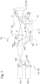
- Figure 7 shows another embodiment of the light source device 102, 302 comprising a modified light shaping system 770.
- the third optical path OP3 extending from the beam expander 658 directly forms the optical output for supplying the excitation light E and the manipulation light M to the optical system 106, 306, the embodiment shown in Figure 7 provides for a separation of the excitation light E and the manipulation light M subsequent to the beam expander 658 as explained hereinafter.
- the beam shaping system 770 of Figure 7 comprises a splitting element 772, e.g. a switchable mirror or a dichroic element which is configured to spatially separate the excitation light E and the manipulation light M.
- a dichroic element may only be used as splitting element in case that the excitation light E and the manipulation light M output from the light sources 650, 652 have different wavelengths.
- a switchable mirror may be used irrespectively of the wavelengths of the excitation light E and the manipulation light M.
- an anamorphic optical element 773 e.g. a cylinder lens, is provided which is configured to optically shape the excitation light E such that a focus with elliptical cross-section is created in the image-side focal plane of the objective 108.
- a long axis of the elliptical cross-section in the image-side focal plane of the objective 108 extends in y-direction, whereas a short axis extends in x-direction.
- the plane illuminated with the light sheet LS within the specimen 110 extends in x-direction.
- the plane of drawing in Figure 7 is perpendicular to the plane of drawing in Figures 1 to 5 .
- the manipulation light M propagates in a fifth optical path OP5 extending from the splitting element 772 to the light shaping element 760 which may comprise a DM, DMD, SLM and/or an ETL.
- the light shaping elements 760 may be used to shift the focus of the manipulation light M in z-direction.
- an ETL may preferably be used.
- the light shaping system 770 further comprises two lenses 762, 764 and a scanner 766 having a tilt axis 768 which is oriented in z-direction. By tilting the scanner 766 about the tilt axis 768, the manipulation light M can be displaced in x-direction.
- the light shaping system 770 further comprises an output merging element 774 which is configured to merge the fourth optical path OP4 and the fifth optical path OP5 in a sixth optical path OP6 which extends to the tube lens 112, 305 of the optical system 106, 306. Accordingly, the sixth optical path OP6 represents the common optical path which is used to output the excitation light E and the manipulation light M in a collinear, i.e. spatially coinciding manner to the optical system 106, 306.
- the output merging element 774 may be formed by a switchable mirror or a dichroic element.
- the scanner 766 is preferably located in the rear focal plane of the tube lens 112, 305 having the rear focal length f1.
- the light shaping element 760 may be located in a plane which is conjugate to the object-side focal plane of the objective 108.
- each of the light shaping element 760 and the scanner 766 may be located in a plane which is conjugated to the image-side focal plane of the objective 108.
- the afore-mentioned embodiments of the light source device 102, 302 are to be understood merely as examples.
- the light source device is not limited to a configuration in which the excitation light E and the manipulation light M are output in a collinear manner, i.e. along a common optical path.
- two separate optical paths for coupling the excitation light E and the manipulation light M into the optical system 106 may be provided.
- the embodiments shown in Figures 6 and 7 may be modified to adapt the configurations shown therein to a light source device having two separate optical outputs.
- such a modification may be achieved by omitting the output merging element 774.
- the excitation light E and the manipulation light M is coupled into the optical system 106, 306 along the two separate optical paths OP4, OP5, respectively.
- aspects have been described in the context of an apparatus, it is clear that these aspects also represent a description of the corresponding method, where a block or device corresponds to a method step or a feature of a method step. Analogously, aspects described in the context of a method step also represent a description of a corresponding block or item or feature of a corresponding apparatus.
- Some or all of the method steps may be executed by (or using) a hardware apparatus, like for example, a processor, a microprocessor, a programmable computer or an electronic circuit. In some embodiments, some one or more of the most important method steps may be executed by such an apparatus.
- embodiments of the invention can be implemented in hardware or in software.
- the implementation can be performed using a non-transitory storage medium such as a digital storage medium, for example a floppy disc, a DVD, a Blu-Ray, a CD, a ROM, a PROM, and EPROM, an EEPROM or a FLASH memory, having electronically readable control signals stored thereon, which cooperate (or are capable of cooperating) with a programmable computer system such that the respective method is performed. Therefore, the digital storage medium may be computer readable.
- Some embodiments according to the invention comprise a data carrier having electronically readable control signals, which are capable of cooperating with a programmable computer system, such that one of the methods described herein is performed.
- embodiments of the present invention can be implemented as a computer program product with a program code, the program code being operative for performing one of the methods when the computer program product runs on a computer.
- the program code may, for example, be stored on a machine readable carrier.
- inventions comprise the computer program for performing one of the methods described herein, stored on a machine readable carrier.
- an embodiment of the present invention is, therefore, a computer program having a program code for performing one of the methods described herein, when the computer program runs on a computer.
- a further embodiment of the present invention is, therefore, a storage medium (or a data carrier, or a computer-readable medium) comprising, stored thereon, the computer program for performing one of the methods described herein when it is performed by a processor.
- the data carrier, the digital storage medium or the recorded medium are typically tangible and/or non-transitionary.
- a further embodiment of the present invention is an apparatus as described herein comprising a processor and the storage medium.
- a further embodiment of the invention is, therefore, a data stream or a sequence of signals representing the computer program for performing one of the methods described herein.
- the data stream or the sequence of signals may, for example, be configured to be transferred via a data communication connection, for example, via the internet.
- a further embodiment comprises a processing means, for example, a computer or a programmable logic device, configured to, or adapted to, perform one of the methods described herein.
- a processing means for example, a computer or a programmable logic device, configured to, or adapted to, perform one of the methods described herein.
- a further embodiment comprises a computer having installed thereon the computer program for performing one of the methods described herein.
- a further embodiment according to the invention comprises an apparatus or a system configured to transfer (for example, electronically or optically) a computer program for performing one of the methods described herein to a receiver.
- the receiver may, for example, be a computer, a mobile device, a memory device or the like.
- the apparatus or system may, for example, comprise a file server for transferring the computer program to the receiver.
- a programmable logic device for example, a field programmable gate array
- a field programmable gate array may cooperate with a microprocessor in order to perform one of the methods described herein.
- the methods are preferably performed by any hardware apparatus.
Landscapes
- Physics & Mathematics (AREA)
- Chemical & Material Sciences (AREA)
- Analytical Chemistry (AREA)
- General Physics & Mathematics (AREA)
- Optics & Photonics (AREA)
- Health & Medical Sciences (AREA)
- Biochemistry (AREA)
- Life Sciences & Earth Sciences (AREA)
- Nuclear Medicine, Radiotherapy & Molecular Imaging (AREA)
- General Health & Medical Sciences (AREA)
- Immunology (AREA)
- Pathology (AREA)
- Engineering & Computer Science (AREA)
- Multimedia (AREA)
- Computer Vision & Pattern Recognition (AREA)
- Microscoopes, Condenser (AREA)
- Investigating, Analyzing Materials By Fluorescence Or Luminescence (AREA)
Claims (20)
- Microscope (100, 100a, 100b) à fluorescence à feuillet de lumière, comprenant :un dispositif (102, 202, 302) formant source de lumière, configuré pour émettre une lumière d'excitation (E) adaptée à l'induction d'une lumière fluorescente (F) émise à partir d'un échantillon (110),un dispositif (104, 304) formant détecteur, configuré pour détecter la lumière fluorescente (F) provenant de l'échantillon (110), etun système optique (106, 306), configuré pour éclairer l'échantillon (110) avec un feuillet de lumière (LS) formé à partir de la lumière d'excitation (E) et pour guider la lumière fluorescente (F) provenant de l'échantillon (110) éclairé vers le dispositif (104, 304) formant détecteur,dans lequel le système optique (106, 306) comprend un objectif (108) orienté vers l'échantillon (110), l'objectif (108) étant configuré pour collecter la lumière fluorescente (F) émise par l'échantillon (110),dans lequel le système optique (106, 306) est configuré pour éclairer l'échantillon (110) avec le feuillet de lumière (LS) à travers l'objectif (108), etdans lequel le dispositif (102, 202, 302) source de lumière est en outre configuré pour émettre une lumière de manipulation (M) adaptée à la photomanipulation de l'échantillon (110),dans lequel le système optique (106, 306) est en outre configuré pour diriger la lumière de manipulation (M) à travers l'objectif (108) à travers une pupille d'entrée (EP) de celui-ci sur l'échantillon (110) le long d'une direction de propagation de lumière qui est différente d'une direction de propagation de lumière du feuillet de lumière (LS), etdans lequel le système optique (106, 306) comprend un dispositif (116, 316) à miroir de balayage incluant au moins un miroir (122, 332, 334) inclinable qui est inclinable de façon à réfléchir la lumière d'excitation (E) pour déplacer le feuillet de lumière (LS) dans son ensemble à travers l'échantillon (110) dans une direction de balayage de feuillet de lumière transversale à la direction de propagation de lumière du feuillet de lumière (LS),caractérisé en ce que le système optique (106, 306) est configuré pour diriger la lumière de manipulation (M) à travers une sous-zone spatialement limitée de la pupille d'entrée (EP) de l'objectif (108) sur l'échantillon (110) ;dans lequel ledit au moins un miroir (122, 332, 334) de balayage est inclinable pour réfléchir à la fois la lumière d'excitation (E) et la lumière de manipulation (M).
- Microscope (100, 100a, 100b) à fluorescence à feuillet de lumière selon la revendication 1, dans lequel la sous-zone spatialement limitée est située décalée par rapport à un centre de la pupille d'entrée (EP) de l'objectif (108).
- Microscope (100, 100a, 100b) à fluorescence à feuillet de lumière selon la revendication 2, dans lequel le système optique (106, 306) est configuré pour diriger la lumière d'excitation (E) à travers une autre sous-zone spatialement limitée de la pupille d'entrée (EP) sur ledit échantillon (110), ladite autre sous-zone étant située décalée par rapport à la sous-zone à travers laquelle la lumière de manipulation (M) est dirigée sur ledit échantillon (110).
- Microscope (100, 100a, 100b) à fluorescence à feuillet de lumière selon l'une des revendications précédentes, dans lequel la direction de propagation de lumière de la lumière de manipulation (M) émanant de l'objectif (108) vers l'échantillon (110) présente un angle par rapport à une direction opposée à une direction de propagation de lumière de la lumière fluorescente émise par l'échantillon dans une plage angulaire de 0 à ± 45°.
- Microscope (100, 100a) à fluorescence à feuillet de lumière selon l'une des revendications précédentes, dans lequel le dispositif (116) de miroir de balayage comprend une lentille (118) de balayage et un seul miroir (122) inclinable qui est situé dans un plan focal arrière de la lentille (118) de balayage.
- Microscope (100b) à fluorescence à feuillet de lumière selon l'une des revendications 1 à 4, dans lequel le dispositif (316) de miroir de balayage comprend deux miroirs (332, 334) inclinables situés décalés l'un par rapport à l'autre le long d'un axe (O) optique du système optique (306).
- Microscope (100, 100a, 100b) à fluorescence à feuillet de lumière selon l'une des revendications précédentes, dans lequel le dispositif (116, 316) de miroir de balayage est configuré pour déplacer un rayon principal de la lumière d'excitation (E) en parallèle lorsque la lumière d'excitation (E) est réfléchie par ledit au moins un miroir (122, 332, 334) de balayage.
- Microscope (100, 100a, 100b) à fluorescence à feuillet de lumière selon l'une des revendications précédentes, dans lequel ledit au moins un miroir (122, 332, 334) inclinable est inclinable pour réfléchir la lumière fluorescente (F) collectée par l'objectif (108) vers le dispositif (104, 304) formant détecteur.
- Microscope (100) à fluorescence à feuillet de lumière selon l'une des revendications précédentes, comprenant une unité (126) de déplacement optique configurée pour déplacer une position incidente de la lumière de manipulation (M) sur ledit au moins un miroir (122) inclinable pour changer la direction de propagation de lumière de la lumière de manipulation (M) dirigée sur l'échantillon (110) indépendamment de la direction de propagation de lumière de la lumière fluorescente (F) et/ou indépendamment de la direction de propagation de lumière du feuillet de lumière (LS).
- Microscope (100) à fluorescence à feuillet de lumière selon la revendication 9, dans lequel l'unité (126) de déplacement optique comprend au moins un élément réfléchissant ou émettant la lumière de manipulation (M), ledit élément étant mobile pour déplacer la position incidente de la lumière de manipulation (M) sur ledit au moins un miroir (122) inclinable.
- Microscope (100, 100b) à fluorescence à feuillet de lumière selon l'une des revendications précédentes, dans lequel le dispositif (102, 302) de source de lumière est configuré pour émettre la lumière d'excitation (E) et la lumière de manipulation (M) le long d'un trajet optique commun dans le système optique (106, 306).
- Microscope (100, 100b) à fluorescence à feuillet de lumière selon la revendication 11, dans lequel le dispositif (102, 302) de source de lumière comprend au moins une source (650) de lumière d'excitation configurée pour émettre la lumière d'excitation (E) le long d'au moins un premier trajet (OP1) optique et au moins une source (652) de lumière de manipulation configurée pour émettre la lumière de manipulation (M) le long d'au moins un deuxième trajet (OP2) optique,
dans lequel le dispositif (102, 302) de source de lumière comprend en outre un système (670, 770) de mise en forme de lumière présentant une entrée optique formée par les premier et deuxième trajets (OP1, OP2) optiques et une sortie optique formée par le trajet optique commun, ledit système (670, 770) de mise en forme de lumière étant configuré pour mettre en forme sélectivement au moins l'une de la lumière d'excitation (E) et de la lumière de manipulation (M). - Microscope (100, 100b) à fluorescence à feuillet de lumière selon la revendication 12, dans lequel le dispositif (102, 302) de source de lumière est commutable entre un mode de fonctionnement d'excitation pour émettre uniquement la lumière d'excitation (E) et un mode de fonctionnement de manipulation pour émettre uniquement la lumière de manipulation (M).
- Microscope (100, 100b) à fluorescence à feuillet de lumière selon la revendication 12 ou la revendication 13, dans lequel le système (670, 770) de mise en forme de lumière comprend un élément (654) de fusion d'entrée configuré pour fusionner les premier et deuxième trajets (OP1, OP2) optiques dans un troisième trajet (OP3) optique.
- Microscope (100, 100b) à fluorescence à feuillet de lumière selon la revendication 14, dans lequel le système (670, 770) de mise en forme de lumière inclut un élargisseur (658) de faisceau situé dans le troisième trajet (OP3) optique.
- Microscope (100, 100b) à fluorescence à feuillet de lumière selon la revendication 14 ou la revendication 15, dans lequel le trajet optique commun est formé par le troisième trajet (OP3) optique,dans lequel le système (670) de mise en forme de lumière comprend au moins un élément (660) de mise en forme de lumière et un scanner (666) qui sont situés dans le trajet optique commun,dans lequel, dans le mode de fonctionnement d'excitation, l'élément (660) de mise en forme de lumière est configuré pour ne pas mettre en forme la lumière d'excitation (E) et le scanner (666) est configuré pour provoquer un mouvement de balayage de la lumière d'excitation (E) dans une direction prédéterminée transversale à la direction de propagation de lumière de la lumière d'excitation (E) pour générer le feuillet de lumière (LS), etdans lequel, dans le mode de fonctionnement de manipulation, l'élément de mise en forme de lumière est configuré pour mettre en forme la lumière de manipulation (M) et le scanner (666) est configuré pour ajuster un déplacement de la lumière de manipulation (M) dans ladite direction prédéterminée.
- Microscope (100, 100b) à fluorescence à feuillet de lumière selon l'une des revendications 1 à 15, dans lequel le système (770) de mise en forme de lumière inclut un élément (772) de séparation situé dans le troisième trajet (OP3) optique et configuré pour séparer spatialement la lumière d'excitation (E) et la lumière de manipulation (M) l'une de l'autre, ladite lumière d'excitation (E) se propageant dans un quatrième trajet (OP4) optique et ladite lumière de manipulation (M) se propageant dans un cinquième trajet (OP5) optique, et un élément (774) de fusion de sortie configuré pour fusionner les quatrième et cinquième trajets (OP4, OP5) optiques dans ledit trajet optique commun,dans lequel le système (770) de mise en forme de lumière comprend un élément (773) optique anamorphe situé dans le quatrième trajet (OP4) optique, ledit élément (773) optique anamorphe étant configuré pour générer le feuillet de lumière à partir de la lumière d'excitation (E), etdans lequel le système (770) de mise en forme de lumière comprend au moins un élément (760) de mise en forme de lumière et/ou un scanner (766) situé dans le cinquième trajet (OP5) optique, ledit élément (760) optique de mise en forme de lumière étant configuré pour mettre en forme la lumière de manipulation (M) et ledit scanner (766) étant configuré pour ajuster un déplacement de la lumière de manipulation (M) dans une direction prédéterminée.
- Microscope (100, 100b) à fluorescence à feuillet de lumière selon la revendication 16 ou la revendication 17, dans lequel l'élément (660, 760) de mise en forme de lumière comprend au moins l'un parmi une lentille réglable électriquement, un miroir déformable, un dispositif de miroir numérique et un modulateur de lumière spatiale.
- Microscope (100, 100b) à fluorescence à feuillet de lumière selon l'une des revendications 16 à 18, dans lequel l'élément de mise en forme de lumière est configuré pour déplacer une mise au point de la lumière de manipulation (M) dans la direction de propagation de lumière de celle-ci.
- Procédé de formation d'image d'un échantillon (110) au moyen d'un microscope (100, 100a, 100b) à fluorescence à feuillet de lumière, comprenant les étapes suivantes :émission d'une lumière d'excitation (E) adaptée à l'induction d'une lumière fluorescente (F) émise par l'échantillon (110),éclairage de l'échantillon (110) avec un feuillet de lumière (LS) formé à partir de la lumière d'excitation (E) à travers un objectif (108) d'un système optique (106, 306) du microscope (100, 100a, 100b) à fluorescence à feuillet de lumière,collecte, au moyen de l'objectif (108) orienté vers l'échantillon (110), de la lumière fluorescente (F) provenant de l'échantillon (110) éclairé, etdétection de la lumière fluorescente (F),dans lequel le procédé comprend en outre les étapes suivantes :émission d'une lumière de manipulation (M) adaptée à la photomanipulation de l'échantillon (110),orientation, sur l'échantillon (110), de la lumière de manipulation (M) à travers l'objectif (108) à travers une pupille d'entrée (EP) de celui-ci, selon une direction de propagation de lumière qui est différente d'une direction de propagation de lumière du feuillet de lumière (LS), etinclinaison d'au moins un miroir (122, 332, 334) inclinable inclus dans un dispositif (116, 316) à miroir de balayage du système optique (106, 306) pour réfléchir la lumière d'excitation (E) afin de déplacer le feuillet de lumière (LS) dans son ensemble à travers l'échantillon (110) dans une direction de balayage de feuillet de lumière transversale à la direction de propagation de lumière du feuillet de lumière (LS),caractérisé en ce que la lumière de manipulation (M) est dirigée sur l'échantillon (110) à travers une sous-zone spatialement limitée de la pupille d'entrée (EP) de l'objectif (108), etledit au moins un miroir (122, 332, 334) de balayage est incliné de façon à réfléchir à la fois la lumière d'excitation (E) et la lumière de manipulation (M).
Priority Applications (3)
| Application Number | Priority Date | Filing Date | Title |
|---|---|---|---|
| EP19213913.7A EP3832369B1 (fr) | 2019-12-05 | 2019-12-05 | Microscope à fluorescence par feuille lumineuse |
| US17/110,455 US11709137B2 (en) | 2019-12-05 | 2020-12-03 | Light sheet fluorescence microscope |
| CN202011399322.XA CN112925089B (zh) | 2019-12-05 | 2020-12-04 | 光片荧光显微镜 |
Applications Claiming Priority (1)
| Application Number | Priority Date | Filing Date | Title |
|---|---|---|---|
| EP19213913.7A EP3832369B1 (fr) | 2019-12-05 | 2019-12-05 | Microscope à fluorescence par feuille lumineuse |
Publications (3)
| Publication Number | Publication Date |
|---|---|
| EP3832369A1 EP3832369A1 (fr) | 2021-06-09 |
| EP3832369C0 EP3832369C0 (fr) | 2025-06-18 |
| EP3832369B1 true EP3832369B1 (fr) | 2025-06-18 |
Family
ID=68808033
Family Applications (1)
| Application Number | Title | Priority Date | Filing Date |
|---|---|---|---|
| EP19213913.7A Active EP3832369B1 (fr) | 2019-12-05 | 2019-12-05 | Microscope à fluorescence par feuille lumineuse |
Country Status (3)
| Country | Link |
|---|---|
| US (1) | US11709137B2 (fr) |
| EP (1) | EP3832369B1 (fr) |
| CN (1) | CN112925089B (fr) |
Families Citing this family (5)
| Publication number | Priority date | Publication date | Assignee | Title |
|---|---|---|---|---|
| JP2019066706A (ja) * | 2017-10-02 | 2019-04-25 | ソニー株式会社 | 蛍光顕微鏡装置及び蛍光顕微鏡システム |
| JP7380569B2 (ja) | 2018-08-09 | 2023-11-15 | ソニーグループ株式会社 | 光学顕微鏡装置及び光学顕微鏡システム |
| CN116183570B (zh) * | 2023-02-15 | 2025-09-23 | 华中科技大学 | 一种斜照明多色荧光显微成像系统 |
| CN116107076B (zh) * | 2023-04-17 | 2023-07-07 | 武汉慧观生物科技有限公司 | 一种单物镜光片三维荧光成像系统 |
| EP4528351A4 (fr) * | 2023-04-17 | 2025-08-13 | Wuhan Smartview Biotechnology Co Ltd | Système d'imagerie par fluorescence tridimensionnelle à feuille de lumière à objectif unique |
Family Cites Families (8)
| Publication number | Priority date | Publication date | Assignee | Title |
|---|---|---|---|---|
| DE102004034957A1 (de) * | 2004-07-16 | 2006-02-02 | Carl Zeiss Jena Gmbh | Anordnung zur mikroskopischen Beobachtung und/oder Detektion und Verwendung |
| DE102007047464B4 (de) | 2007-09-28 | 2023-03-02 | Carl Zeiss Microscopy Gmbh | Optische Anordnung zur Photomanipulation |
| DE102013213781A1 (de) | 2013-03-20 | 2014-09-25 | Leica Microsystems Cms Gmbh | Verfahren und optische Anordnung zum Manipulieren und Abbilden einer mikroskopischen Probe |
| JP7180964B2 (ja) * | 2014-01-17 | 2022-11-30 | ザ・トラスティーズ・オブ・コロンビア・ユニバーシティ・イン・ザ・シティ・オブ・ニューヨーク | 三次元イメージング装置および方法 |
| US10061111B2 (en) * | 2014-01-17 | 2018-08-28 | The Trustees Of Columbia University In The City Of New York | Systems and methods for three dimensional imaging |
| DE102016120683A1 (de) | 2016-10-28 | 2018-05-03 | Carl Zeiss Microscopy Gmbh | Lichtblattmikroskop |
| DE102017119478A1 (de) * | 2017-08-25 | 2019-02-28 | Carl Zeiss Microscopy Gmbh | Optische Anordnung zum Scannen von Anregungsstrahlung und/oder Manipulationsstrahlung in einem Laser-Scanning-Mikroskop und Laser-Scanning-Mikroskop |
| GB201913703D0 (en) * | 2019-09-23 | 2019-11-06 | Imperial College Innovations Ltd | Improved oblique plane microscopy |
-
2019
- 2019-12-05 EP EP19213913.7A patent/EP3832369B1/fr active Active
-
2020
- 2020-12-03 US US17/110,455 patent/US11709137B2/en active Active
- 2020-12-04 CN CN202011399322.XA patent/CN112925089B/zh active Active
Also Published As
| Publication number | Publication date |
|---|---|
| EP3832369A1 (fr) | 2021-06-09 |
| EP3832369C0 (fr) | 2025-06-18 |
| CN112925089B (zh) | 2025-10-28 |
| US11709137B2 (en) | 2023-07-25 |
| CN112925089A (zh) | 2021-06-08 |
| US20210172876A1 (en) | 2021-06-10 |
Similar Documents
| Publication | Publication Date | Title |
|---|---|---|
| EP3832369B1 (fr) | Microscope à fluorescence par feuille lumineuse | |
| EP1857853B1 (fr) | Dispositif d'illumination | |
| JP5006694B2 (ja) | 照明装置 | |
| CN111095073B (zh) | 在激光扫描显微镜中扫描激发辐射和/或操纵辐射的光学组件以及激光扫描显微镜 | |
| US6924490B2 (en) | Microscope system | |
| JP5286774B2 (ja) | 顕微鏡装置と、これに用いられる蛍光キューブ | |
| EP2330454B1 (fr) | Microscope à balayage laser | |
| JP2009058776A (ja) | フォーカシング光学系を有する光学系およびこれを用いたレーザ顕微鏡装置 | |
| JP2007506955A (ja) | エバネッセント波照明を備えた走査顕微鏡 | |
| JP6805126B2 (ja) | 微小試料の光学的な検査および/または操作のための方法、顕微鏡、顕微鏡および/または方法の使用、照明装置 | |
| US20070051869A1 (en) | Scanning microscope and method for examining a sample by using scanning microscopy | |
| JP2025515943A (ja) | 超解像度単対物レンズ光学シート顕微結像光学システム及びその結像システム | |
| JP4270884B2 (ja) | 顕微鏡システム | |
| CN114442297A (zh) | 具有光片激发的光场显微术和共焦显微术的显微镜和方法 | |
| JP5463671B2 (ja) | 焦点検出装置、顕微鏡 | |
| US8154796B2 (en) | Microscope apparatus | |
| JP4804726B2 (ja) | 走査型光学観察装置 | |
| US20060087727A1 (en) | Apparatus, system and method for selective photobleaching, imaging and confocal microscopy | |
| EP4127809B1 (fr) | Microscope à feuille de lumière et procédé de manipulation d'une zone cible d'un échantillon | |
| US6855941B1 (en) | Laser microscope | |
| EP4204887B1 (fr) | Microscope | |
| JP4874012B2 (ja) | レーザ走査型顕微鏡およびレーザ走査型顕微鏡の画像取得方法 | |
| JP4939855B2 (ja) | 照明装置およびレーザ走査型顕微鏡 | |
| JP2004212800A (ja) | 顕微鏡照明装置及びそれを用いた共焦点顕微鏡 | |
| JP2009014838A (ja) | 走査型共焦点顕微鏡 |
Legal Events
| Date | Code | Title | Description |
|---|---|---|---|
| PUAI | Public reference made under article 153(3) epc to a published international application that has entered the european phase |
Free format text: ORIGINAL CODE: 0009012 |
|
| STAA | Information on the status of an ep patent application or granted ep patent |
Free format text: STATUS: THE APPLICATION HAS BEEN PUBLISHED |
|
| AK | Designated contracting states |
Kind code of ref document: A1 Designated state(s): AL AT BE BG CH CY CZ DE DK EE ES FI FR GB GR HR HU IE IS IT LI LT LU LV MC MK MT NL NO PL PT RO RS SE SI SK SM TR |
|
| STAA | Information on the status of an ep patent application or granted ep patent |
Free format text: STATUS: REQUEST FOR EXAMINATION WAS MADE |
|
| 17P | Request for examination filed |
Effective date: 20211209 |
|
| RBV | Designated contracting states (corrected) |
Designated state(s): AL AT BE BG CH CY CZ DE DK EE ES FI FR GB GR HR HU IE IS IT LI LT LU LV MC MK MT NL NO PL PT RO RS SE SI SK SM TR |
|
| P01 | Opt-out of the competence of the unified patent court (upc) registered |
Effective date: 20230414 |
|
| STAA | Information on the status of an ep patent application or granted ep patent |
Free format text: STATUS: EXAMINATION IS IN PROGRESS |
|
| 17Q | First examination report despatched |
Effective date: 20230626 |
|
| GRAP | Despatch of communication of intention to grant a patent |
Free format text: ORIGINAL CODE: EPIDOSNIGR1 |
|
| STAA | Information on the status of an ep patent application or granted ep patent |
Free format text: STATUS: GRANT OF PATENT IS INTENDED |
|
| INTG | Intention to grant announced |
Effective date: 20250206 |
|
| GRAS | Grant fee paid |
Free format text: ORIGINAL CODE: EPIDOSNIGR3 |
|
| GRAA | (expected) grant |
Free format text: ORIGINAL CODE: 0009210 |
|
| STAA | Information on the status of an ep patent application or granted ep patent |
Free format text: STATUS: THE PATENT HAS BEEN GRANTED |
|
| AK | Designated contracting states |
Kind code of ref document: B1 Designated state(s): AL AT BE BG CH CY CZ DE DK EE ES FI FR GB GR HR HU IE IS IT LI LT LU LV MC MK MT NL NO PL PT RO RS SE SI SK SM TR |
|
| REG | Reference to a national code |
Ref country code: GB Ref legal event code: FG4D |
|
| REG | Reference to a national code |
Ref country code: CH Ref legal event code: EP |
|
| REG | Reference to a national code |
Ref country code: DE Ref legal event code: R096 Ref document number: 602019071196 Country of ref document: DE |
|
| REG | Reference to a national code |
Ref country code: CH Ref legal event code: EP |
|
| REG | Reference to a national code |
Ref country code: IE Ref legal event code: FG4D |
|
| U01 | Request for unitary effect filed |
Effective date: 20250618 |
|
| P04 | Withdrawal of opt-out of the competence of the unified patent court (upc) registered |
Free format text: CASE NUMBER: APP_30022/2025 Effective date: 20250623 |
|
| U07 | Unitary effect registered |
Designated state(s): AT BE BG DE DK EE FI FR IT LT LU LV MT NL PT RO SE SI Effective date: 20250626 |
|
| PG25 | Lapsed in a contracting state [announced via postgrant information from national office to epo] |
Ref country code: NO Free format text: LAPSE BECAUSE OF FAILURE TO SUBMIT A TRANSLATION OF THE DESCRIPTION OR TO PAY THE FEE WITHIN THE PRESCRIBED TIME-LIMIT Effective date: 20250918 Ref country code: GR Free format text: LAPSE BECAUSE OF FAILURE TO SUBMIT A TRANSLATION OF THE DESCRIPTION OR TO PAY THE FEE WITHIN THE PRESCRIBED TIME-LIMIT Effective date: 20250919 |
|
| PG25 | Lapsed in a contracting state [announced via postgrant information from national office to epo] |
Ref country code: HR Free format text: LAPSE BECAUSE OF FAILURE TO SUBMIT A TRANSLATION OF THE DESCRIPTION OR TO PAY THE FEE WITHIN THE PRESCRIBED TIME-LIMIT Effective date: 20250618 |
|
| PG25 | Lapsed in a contracting state [announced via postgrant information from national office to epo] |
Ref country code: RS Free format text: LAPSE BECAUSE OF FAILURE TO SUBMIT A TRANSLATION OF THE DESCRIPTION OR TO PAY THE FEE WITHIN THE PRESCRIBED TIME-LIMIT Effective date: 20250918 |
|
| PG25 | Lapsed in a contracting state [announced via postgrant information from national office to epo] |
Ref country code: IS Free format text: LAPSE BECAUSE OF FAILURE TO SUBMIT A TRANSLATION OF THE DESCRIPTION OR TO PAY THE FEE WITHIN THE PRESCRIBED TIME-LIMIT Effective date: 20251018 |
|
| PGFP | Annual fee paid to national office [announced via postgrant information from national office to epo] |
Ref country code: GB Payment date: 20251223 Year of fee payment: 7 |
|
| PG25 | Lapsed in a contracting state [announced via postgrant information from national office to epo] |
Ref country code: SM Free format text: LAPSE BECAUSE OF FAILURE TO SUBMIT A TRANSLATION OF THE DESCRIPTION OR TO PAY THE FEE WITHIN THE PRESCRIBED TIME-LIMIT Effective date: 20250618 |
|
| PG25 | Lapsed in a contracting state [announced via postgrant information from national office to epo] |
Ref country code: CZ Free format text: LAPSE BECAUSE OF FAILURE TO SUBMIT A TRANSLATION OF THE DESCRIPTION OR TO PAY THE FEE WITHIN THE PRESCRIBED TIME-LIMIT Effective date: 20250618 |
|
| PG25 | Lapsed in a contracting state [announced via postgrant information from national office to epo] |
Ref country code: PL Free format text: LAPSE BECAUSE OF FAILURE TO SUBMIT A TRANSLATION OF THE DESCRIPTION OR TO PAY THE FEE WITHIN THE PRESCRIBED TIME-LIMIT Effective date: 20250618 |
|
| PG25 | Lapsed in a contracting state [announced via postgrant information from national office to epo] |
Ref country code: SK Free format text: LAPSE BECAUSE OF FAILURE TO SUBMIT A TRANSLATION OF THE DESCRIPTION OR TO PAY THE FEE WITHIN THE PRESCRIBED TIME-LIMIT Effective date: 20250618 |
|
| U20 | Renewal fee for the european patent with unitary effect paid |
Year of fee payment: 7 Effective date: 20251223 |
|
| PG25 | Lapsed in a contracting state [announced via postgrant information from national office to epo] |
Ref country code: ES Free format text: LAPSE BECAUSE OF FAILURE TO SUBMIT A TRANSLATION OF THE DESCRIPTION OR TO PAY THE FEE WITHIN THE PRESCRIBED TIME-LIMIT Effective date: 20250618 |
|
| PLBE | No opposition filed within time limit |
Free format text: ORIGINAL CODE: 0009261 |
|
| STAA | Information on the status of an ep patent application or granted ep patent |
Free format text: STATUS: NO OPPOSITION FILED WITHIN TIME LIMIT |
|
| REG | Reference to a national code |
Ref country code: CH Ref legal event code: L10 Free format text: ST27 STATUS EVENT CODE: U-0-0-L10-L00 (AS PROVIDED BY THE NATIONAL OFFICE) Effective date: 20260430 |