EP3833496B1 - Verfahren zur herstellung von mehrmaterialrolle - Google Patents
Verfahren zur herstellung von mehrmaterialrolle Download PDFInfo
- Publication number
- EP3833496B1 EP3833496B1 EP20756087.1A EP20756087A EP3833496B1 EP 3833496 B1 EP3833496 B1 EP 3833496B1 EP 20756087 A EP20756087 A EP 20756087A EP 3833496 B1 EP3833496 B1 EP 3833496B1
- Authority
- EP
- European Patent Office
- Prior art keywords
- roll
- ingot
- special
- base material
- special material
- Prior art date
- Legal status (The legal status is an assumption and is not a legal conclusion. Google has not performed a legal analysis and makes no representation as to the accuracy of the status listed.)
- Active
Links
Images





Classifications
-
- C—CHEMISTRY; METALLURGY
- C21—METALLURGY OF IRON
- C21D—MODIFYING THE PHYSICAL STRUCTURE OF FERROUS METALS; GENERAL DEVICES FOR HEAT TREATMENT OF FERROUS OR NON-FERROUS METALS OR ALLOYS; MAKING METAL MALLEABLE, e.g. BY DECARBURISATION OR TEMPERING
- C21D7/00—Modifying the physical properties of iron or steel by deformation
- C21D7/13—Modifying the physical properties of iron or steel by deformation by hot working
-
- B—PERFORMING OPERATIONS; TRANSPORTING
- B21—MECHANICAL METAL-WORKING WITHOUT ESSENTIALLY REMOVING MATERIAL; PUNCHING METAL
- B21K—MAKING FORGED OR PRESSED METAL PRODUCTS, e.g. HORSE-SHOES, RIVETS, BOLTS OR WHEELS
- B21K1/00—Making machine elements
- B21K1/02—Making machine elements balls, rolls, or rollers, e.g. for bearings
-
- B—PERFORMING OPERATIONS; TRANSPORTING
- B21—MECHANICAL METAL-WORKING WITHOUT ESSENTIALLY REMOVING MATERIAL; PUNCHING METAL
- B21B—ROLLING OF METAL
- B21B27/00—Rolls, roll alloys or roll fabrication; Lubricating, cooling or heating rolls while in use
- B21B27/02—Shape or construction of rolls
-
- B—PERFORMING OPERATIONS; TRANSPORTING
- B22—CASTING; POWDER METALLURGY
- B22F—WORKING METALLIC POWDER; MANUFACTURE OF ARTICLES FROM METALLIC POWDER; MAKING METALLIC POWDER; APPARATUS OR DEVICES SPECIALLY ADAPTED FOR METALLIC POWDER
- B22F10/00—Additive manufacturing of workpieces or articles from metallic powder
- B22F10/20—Direct sintering or melting
- B22F10/22—Direct deposition of molten metal
-
- B—PERFORMING OPERATIONS; TRANSPORTING
- B22—CASTING; POWDER METALLURGY
- B22F—WORKING METALLIC POWDER; MANUFACTURE OF ARTICLES FROM METALLIC POWDER; MAKING METALLIC POWDER; APPARATUS OR DEVICES SPECIALLY ADAPTED FOR METALLIC POWDER
- B22F3/00—Manufacture of workpieces or articles from metallic powder characterised by the manner of compacting or sintering; Apparatus specially adapted therefor ; Presses and furnaces
- B22F3/115—Manufacture of workpieces or articles from metallic powder characterised by the manner of compacting or sintering; Apparatus specially adapted therefor ; Presses and furnaces by spraying molten metal, i.e. spray sintering, spray casting
-
- B—PERFORMING OPERATIONS; TRANSPORTING
- B22—CASTING; POWDER METALLURGY
- B22F—WORKING METALLIC POWDER; MANUFACTURE OF ARTICLES FROM METALLIC POWDER; MAKING METALLIC POWDER; APPARATUS OR DEVICES SPECIALLY ADAPTED FOR METALLIC POWDER
- B22F7/00—Manufacture of composite layers, workpieces, or articles, comprising metallic powder, by sintering the powder, with or without compacting wherein at least one part is obtained by sintering or compression
- B22F7/06—Manufacture of composite layers, workpieces, or articles, comprising metallic powder, by sintering the powder, with or without compacting wherein at least one part is obtained by sintering or compression of composite workpieces or articles from parts, e.g. to form tipped tools
- B22F7/062—Manufacture of composite layers, workpieces, or articles, comprising metallic powder, by sintering the powder, with or without compacting wherein at least one part is obtained by sintering or compression of composite workpieces or articles from parts, e.g. to form tipped tools involving the connection or repairing of preformed parts
-
- B—PERFORMING OPERATIONS; TRANSPORTING
- B22—CASTING; POWDER METALLURGY
- B22F—WORKING METALLIC POWDER; MANUFACTURE OF ARTICLES FROM METALLIC POWDER; MAKING METALLIC POWDER; APPARATUS OR DEVICES SPECIALLY ADAPTED FOR METALLIC POWDER
- B22F7/00—Manufacture of composite layers, workpieces, or articles, comprising metallic powder, by sintering the powder, with or without compacting wherein at least one part is obtained by sintering or compression
- B22F7/06—Manufacture of composite layers, workpieces, or articles, comprising metallic powder, by sintering the powder, with or without compacting wherein at least one part is obtained by sintering or compression of composite workpieces or articles from parts, e.g. to form tipped tools
- B22F7/08—Manufacture of composite layers, workpieces, or articles, comprising metallic powder, by sintering the powder, with or without compacting wherein at least one part is obtained by sintering or compression of composite workpieces or articles from parts, e.g. to form tipped tools with one or more parts not made from powder
-
- B—PERFORMING OPERATIONS; TRANSPORTING
- B33—ADDITIVE MANUFACTURING TECHNOLOGY
- B33Y—ADDITIVE MANUFACTURING, i.e. MANUFACTURING OF THREE-DIMENSIONAL [3D] OBJECTS BY ADDITIVE DEPOSITION, ADDITIVE AGGLOMERATION OR ADDITIVE LAYERING, e.g. BY 3D PRINTING, STEREOLITHOGRAPHY OR SELECTIVE LASER SINTERING
- B33Y40/00—Auxiliary operations or equipment, e.g. for material handling
- B33Y40/20—Post-treatment, e.g. curing, coating or polishing
-
- B—PERFORMING OPERATIONS; TRANSPORTING
- B33—ADDITIVE MANUFACTURING TECHNOLOGY
- B33Y—ADDITIVE MANUFACTURING, i.e. MANUFACTURING OF THREE-DIMENSIONAL [3D] OBJECTS BY ADDITIVE DEPOSITION, ADDITIVE AGGLOMERATION OR ADDITIVE LAYERING, e.g. BY 3D PRINTING, STEREOLITHOGRAPHY OR SELECTIVE LASER SINTERING
- B33Y70/00—Materials specially adapted for additive manufacturing
-
- B—PERFORMING OPERATIONS; TRANSPORTING
- B33—ADDITIVE MANUFACTURING TECHNOLOGY
- B33Y—ADDITIVE MANUFACTURING, i.e. MANUFACTURING OF THREE-DIMENSIONAL [3D] OBJECTS BY ADDITIVE DEPOSITION, ADDITIVE AGGLOMERATION OR ADDITIVE LAYERING, e.g. BY 3D PRINTING, STEREOLITHOGRAPHY OR SELECTIVE LASER SINTERING
- B33Y80/00—Products made by additive manufacturing
-
- C—CHEMISTRY; METALLURGY
- C21—METALLURGY OF IRON
- C21D—MODIFYING THE PHYSICAL STRUCTURE OF FERROUS METALS; GENERAL DEVICES FOR HEAT TREATMENT OF FERROUS OR NON-FERROUS METALS OR ALLOYS; MAKING METAL MALLEABLE, e.g. BY DECARBURISATION OR TEMPERING
- C21D9/00—Heat treatment, e.g. annealing, hardening, quenching or tempering, adapted for particular articles; Furnaces therefor
- C21D9/0006—Details, accessories not peculiar to any of the following furnaces
- C21D9/0012—Rolls; Roll arrangements
-
- C—CHEMISTRY; METALLURGY
- C21—METALLURGY OF IRON
- C21D—MODIFYING THE PHYSICAL STRUCTURE OF FERROUS METALS; GENERAL DEVICES FOR HEAT TREATMENT OF FERROUS OR NON-FERROUS METALS OR ALLOYS; MAKING METAL MALLEABLE, e.g. BY DECARBURISATION OR TEMPERING
- C21D9/00—Heat treatment, e.g. annealing, hardening, quenching or tempering, adapted for particular articles; Furnaces therefor
- C21D9/38—Heat treatment, e.g. annealing, hardening, quenching or tempering, adapted for particular articles; Furnaces therefor for roll bodies
-
- C—CHEMISTRY; METALLURGY
- C22—METALLURGY; FERROUS OR NON-FERROUS ALLOYS; TREATMENT OF ALLOYS OR NON-FERROUS METALS
- C22C—ALLOYS
- C22C33/00—Making ferrous alloys
- C22C33/02—Making ferrous alloys by powder metallurgy
- C22C33/0257—Making ferrous alloys by powder metallurgy characterised by the range of the alloying elements
- C22C33/0278—Making ferrous alloys by powder metallurgy characterised by the range of the alloying elements with at least one alloying element having a minimum content above 5%
-
- C—CHEMISTRY; METALLURGY
- C22—METALLURGY; FERROUS OR NON-FERROUS ALLOYS; TREATMENT OF ALLOYS OR NON-FERROUS METALS
- C22C—ALLOYS
- C22C33/00—Making ferrous alloys
- C22C33/02—Making ferrous alloys by powder metallurgy
- C22C33/0257—Making ferrous alloys by powder metallurgy characterised by the range of the alloying elements
- C22C33/0278—Making ferrous alloys by powder metallurgy characterised by the range of the alloying elements with at least one alloying element having a minimum content above 5%
- C22C33/0285—Making ferrous alloys by powder metallurgy characterised by the range of the alloying elements with at least one alloying element having a minimum content above 5% with Cr, Co, or Ni having a minimum content higher than 5%
-
- C—CHEMISTRY; METALLURGY
- C22—METALLURGY; FERROUS OR NON-FERROUS ALLOYS; TREATMENT OF ALLOYS OR NON-FERROUS METALS
- C22C—ALLOYS
- C22C33/00—Making ferrous alloys
- C22C33/02—Making ferrous alloys by powder metallurgy
- C22C33/0257—Making ferrous alloys by powder metallurgy characterised by the range of the alloying elements
- C22C33/0278—Making ferrous alloys by powder metallurgy characterised by the range of the alloying elements with at least one alloying element having a minimum content above 5%
- C22C33/0292—Making ferrous alloys by powder metallurgy characterised by the range of the alloying elements with at least one alloying element having a minimum content above 5% with more than 5% preformed carbides, nitrides or borides
-
- C—CHEMISTRY; METALLURGY
- C22—METALLURGY; FERROUS OR NON-FERROUS ALLOYS; TREATMENT OF ALLOYS OR NON-FERROUS METALS
- C22C—ALLOYS
- C22C38/00—Ferrous alloys, e.g. steel alloys
-
- B—PERFORMING OPERATIONS; TRANSPORTING
- B22—CASTING; POWDER METALLURGY
- B22F—WORKING METALLIC POWDER; MANUFACTURE OF ARTICLES FROM METALLIC POWDER; MAKING METALLIC POWDER; APPARATUS OR DEVICES SPECIALLY ADAPTED FOR METALLIC POWDER
- B22F2998/00—Supplementary information concerning processes or compositions relating to powder metallurgy
- B22F2998/10—Processes characterised by the sequence of their steps
-
- B—PERFORMING OPERATIONS; TRANSPORTING
- B22—CASTING; POWDER METALLURGY
- B22F—WORKING METALLIC POWDER; MANUFACTURE OF ARTICLES FROM METALLIC POWDER; MAKING METALLIC POWDER; APPARATUS OR DEVICES SPECIALLY ADAPTED FOR METALLIC POWDER
- B22F3/00—Manufacture of workpieces or articles from metallic powder characterised by the manner of compacting or sintering; Apparatus specially adapted therefor ; Presses and furnaces
- B22F3/12—Both compacting and sintering
- B22F3/14—Both compacting and sintering simultaneously
- B22F3/15—Hot isostatic pressing
-
- B—PERFORMING OPERATIONS; TRANSPORTING
- B33—ADDITIVE MANUFACTURING TECHNOLOGY
- B33Y—ADDITIVE MANUFACTURING, i.e. MANUFACTURING OF THREE-DIMENSIONAL [3D] OBJECTS BY ADDITIVE DEPOSITION, ADDITIVE AGGLOMERATION OR ADDITIVE LAYERING, e.g. BY 3D PRINTING, STEREOLITHOGRAPHY OR SELECTIVE LASER SINTERING
- B33Y10/00—Processes of additive manufacturing
-
- C—CHEMISTRY; METALLURGY
- C21—METALLURGY OF IRON
- C21D—MODIFYING THE PHYSICAL STRUCTURE OF FERROUS METALS; GENERAL DEVICES FOR HEAT TREATMENT OF FERROUS OR NON-FERROUS METALS OR ALLOYS; MAKING METAL MALLEABLE, e.g. BY DECARBURISATION OR TEMPERING
- C21D2211/00—Microstructure comprising significant phases
- C21D2211/004—Dispersions; Precipitations
-
- Y—GENERAL TAGGING OF NEW TECHNOLOGICAL DEVELOPMENTS; GENERAL TAGGING OF CROSS-SECTIONAL TECHNOLOGIES SPANNING OVER SEVERAL SECTIONS OF THE IPC; TECHNICAL SUBJECTS COVERED BY FORMER USPC CROSS-REFERENCE ART COLLECTIONS [XRACs] AND DIGESTS
- Y02—TECHNOLOGIES OR APPLICATIONS FOR MITIGATION OR ADAPTATION AGAINST CLIMATE CHANGE
- Y02P—CLIMATE CHANGE MITIGATION TECHNOLOGIES IN THE PRODUCTION OR PROCESSING OF GOODS
- Y02P10/00—Technologies related to metal processing
- Y02P10/25—Process efficiency
Definitions
- the invention relates to the manufacture of hot and cold working multimaterial roll produced from at least two different materials.
- Rolls especially working rolls, are used for the hot and cold rolling of metals like steel, copper, aluminum and titanium.
- Working rolls are subjected in operation for significant mechanical, thermal and chemical loading. The amount and type of loading varies in different areas. Roll working surfaces are subjected during hot rolling to thermal loads including dynamic loads due to the thermal cycling. Additionally, rolling loads result in mechanical dynamic loading for the roll surface. Oxides in the surface of hot rolled material may result in abrasive wear, and adhesive wear may even cause material tear away from the roll working surface as rolled material may weld itself onto the roll surface. During hot rolling high temperatures may result in oxidation of the working surface and the liquid coolant may increase surface corrosion.
- the surface In cold rolls the surface is subjected to significant loads resulting in surface fatigue and adhesion which gradually deteriorate the surface quality and the end product surface quality. Consequently, the surface degradation mechanisms vary depending on the rolling application (hot or cold rolling) as well as depending on which materials and materials shapes are rolled (e.g. plate or bars).
- the roll working surface material should have as homogeneous as behavior as possible in order to avoid uncontrollable lifetime changes and unexpected damages.
- materials should contain minimum amount of material defects like inclusions, cracks or pores which may results in macroscopic defects as fatigue cracks initiate from these starting defects.
- the present working roll materials are various cast or forged ferrous materials which are developed suitable for different applications. Both in case of cast and forged materials material selection and material property development is difficult because of limitations of production methods for increasing alloying level for e.g. improved wear resistance, temperature resistance or mechanical properties. Especially in large cast and forged products, like rolls, due to manufacturing technological limitations there is large grain size, coarse solidification structure and more inhomogeneous alloying element distribution than is small products, also rolls, which makes it more difficult to improve quality and lifetime of rolls.
- Material properties can be improved using optional manufacturing technologies like powder metallurgy or spray forming and for example using electroslag re-melting. All these methods allow more homogeneous roll material. Additionally, especially using manufacturing methods based on powder metallurgy and spray forming it is possible to increase amount of alloying more than in some other methods based on casting or electroslag re-melting technology, in order to increase roll lifetime without manufacturing technology problems. On the other hand, these production technologies are more expensive than when using casting or forging technologies. This is caused by more expensive manufacturing methods due to higher cost production equipment and more complicated manufacturing solutions, also due to higher content of alloying elements used to improve lifetime.
- Hot isostatic pressing is used to produce powder metallurgical rolls which is performed in special pressure vessel capable for high pressure and high temperature.
- pressure vessel capable for high pressure and high temperature.
- Large rolls refer typically to rolls that has length of more than 3,5 meters or more than 4 meters.
- the length of the roll means dimension which is the largest. Typically, this dimension is the dimension of the axial length of the rolls. This relates both for monolithic rolls and multimaterial rolls produced from more than one material.
- hot isostatic pressing it is possible that contaminants are left on the surface of large components and hot working reduces their impact of mechanical properties of the interface. Additionally, hot working widens diffusion zone between cladding and the base materials which makes the interface less steep and consequently reduces interfacial stresses.
- Spray forming can be also used to manufacture multimaterial rolls by e.g. spray forming first more resistant material onto the surface of base material that forms the working surface of the roll.
- spray forming does not usually reach as reliable adhesion between spray formed materials and base material as by using hot isostatic pressing.
- material properties of spray formed materials, at least as thick material layers or high alloyed materials, are not sufficient for all rolling applications due to the porosity and partially continuous carbide networks.
- casting method has been applied as centrifucal casting method where more durable material forming working surface of the roll is poured first rotating mold and subsequently low alloy steel or cast iron forming base material is poured. This method results in improved adhesion between different materials.
- the surface materials is still cast material having typical limitations of cast steels i.e. coarse inhomogeneous, casting defects and limitations in alloying and improvement in wear resistance.
- weld cladding using different techniques is one additive manufacturing method in addition to spray forming and 3D printing.
- weld cladding situation is the same as in case of cast cladding i.e. metallurgical quality of the cladding, welding defects and limitations in alloying limits its use for manufacture of higher quality, higher alloyed rolls.
- weld cladding can be used for cladding of working surfaces of long rolls because its does not really have in size limitations.
- the metallurgical quality of weld cladding cannot be really improved.
- the use of weld cladding is limited by weldability requirements of the base material as well as need to have the weld cladding materials as welding consumables.
- shrink joining of special materials has been also used like shrink joining of special materials to low alloyed, lower cost base material. These methods are, however, unreliable especially in large rolls and their use has been limited to very small working rolls, e.g. joining of hard metal rings mechanically into steel rolls.
- shrink fitting cylindrical wear resistant special material around base material is not possible for long cylindrical parts and large rolls because reliable assembly of long cylindrical parts is difficult resulting in movement of cylindrical part during rolling operation and possible damage of the cylindrical part and the roll.
- shrink fit cylindrical part may contain residual stresses after assembly and is subjected to significant bending loads during operation which results is movement of shrink fit part during rolling resulting in relative movement with base material and consequently damages in operation.
- Hot working can be used according to patents US 2018243815 A1 and US 2017144205 A1 to increase length of the rolls.
- method in patent US 2018243815 A1 it is possible to produce using weld cladding or hot isostatic pressed powder metallurgy cladding a starting ingot which is subsequently hot worked.
- method described in patent US 2017144205 A1 first a hot isostatic pressed powder metallurgy starting ingot is produced, subsequently the capsule used during hot isostatic pressing is removed and finally both ingot end without cladding are hot worked in order to reach the right length.
- JP H04 59901 describes a manufacturing method of a conjugated roll.
- the roll is a composite with a metal powder sintered on an outer circumferential surface of a solid roll core material.
- a metal capsule is attached around the core material.
- there is an annular space where metal powder is inserted, and this system is thereafter degassed and sealed.
- hot isostatic pressing i.e. HIP
- the metal powder in sintered to the solid roll core with high pressure and high temperature.
- the metal capsule is subsequently heated in its both ends (2a and 2b), and these ends are forged into a certain shape, whereafter the metal capsule is removed.
- a final machining is done to obtain a final predetermined roll shape for the roll stock.
- rolls are considered as rolls having length more than 3 meters, for example more than 3,5 meters or more than 4 meters.
- This length refers to largest single dimensions. Usually this dimension is roll length in axial direction from end to end.
- Excellent properties of the special materials means that working surface is not exposed to unacceptable wear from the point of view of roll operation as a result of interaction between material to be rolled and the roll working surface. This type of wear may result from thermal, mechanical or chemical effects.
- working surface hardness should advantageously be, depending on the application, in hot rolling applications more than HRC50 and in cold rolling applications more than HRC60 so, that working surface carbide size should be less than 15 ⁇ m determined based on biggest dimension.
- Excellent working surface adhesion to the base material means that working surface adhesion is sufficient to prevent its tear or gradual separation due to fatigue as a result of dynamic loads, abnormal loads or thermal loads during operation. Because the loads vary depending on the applications also requirements for the adhesion vary from application to application.
- Special materials are considered as different alloyed wear resistant steels that contain sufficient amount of carbon and combination of carbide forming alloying elements to form good carbide distribution after heat treatment. These materials have carbon content more than 0.8 weight-% and carbide forming elements more than 8 weight-%. When goal is to achieve excellent wear resistant it is possible to use vanadium, tungsten and niobium as carbide forming elements as the carbides formed from these alloying elements are harder than carbides formed with chromium.
- Typical wear resistant special material suitable for multimaterial rolls are e.g. steels AISI D2, AISI M2, AISI M3, AISI M4, AISI A11 and AISI T15, which contain various combinations of alloying elements for achieving suitable combination of properties.
- Base materials are considered as materials that are typically used to manufacture that part of the multimaterial roll which is not in contact with the material to be rolled and is not exposed for same type of wear, heat and corrosion loads as the roll working surface.
- base material has to withstand mechanical loads and same parameters for cladding, hot working and heat treatment as for special material should be suitable for it.
- Suitable base materials are e.g. quenched and tempered steel like DIN 42CrMo4 and carbon steel EN S355.
- This invention is especially suitable for rolls where special material carbide volume fraction is large, at least 8 volume-% and carbide size is limited to below 15 ⁇ m in order to improve ductility and surface fatigue resistance.
- the method according to this invention allows manufacture of roll so that
- This type of preparation includes encapsulation.
- the manufacturing method according to this invention it is possible to produce the roll so that production of material components, joining of material components and preparation for hot working or part of these and combined for one stage after this it is possible to proceed directly for hot working.
- this approach it is possible to use e.g. casting methods to produce multimaterial starting ingot.
- this manufacturing method is suitable for additive manufacturing methods like 3D printing, molten metal spraying, spray forming and even traditional welding or weld cladding.
- additive manufacturing methods like 3D printing, molten metal spraying, spray forming and even traditional welding or weld cladding.
- simultaneous production of special material part and base material part is casting of two different molten materials so that they do not mix with each other in the mold as they are separated using metallic sheets.
- the advantage of producing two materials simultaneously is that if the simultaneous manufacture is performed at elevated temperature their cooling takes place more uniformly than if only other material is manufactured at elevated temperature as the interfacial stresses are reduced. This is realized e.g. when casting both materials according to figure 7a .
- This method also promotes materials for joining to each other via diffusion or partial melting of the interfaces.
- production can be performed so that before the first material has cooled down additive manufacture of other material by molten metal spraying or spray forming starts resulting in cooling rates closer to each other than when other material is entirely cold or just mildly preheated before additive manufacture of the other material. If the first material is solid before joining of the second material it is beneficial to heat it to elevated temperature before manufacture and joining of the second material in order to reduce stresses formed during cooling.
- the production method according to this invention allows manufacture multimaterial long, for example longer than 3 meters rolls from one integrated material ingot so that the joint between materials is based on metallurgical and diffusion joints. This allows avoidance of welded and mechanical joints that are considered unreliable in manufacture of large, longer than e.g. 3 meters rolls.
- Manufacturing method according to this invention allows improvement properties of special materials, their densification or breakdown of carbide or solidification structure using hot working. This enables use of cast technology for the manufacture of special material part because large carbides and carbide net works can be broken finer during hot working.
- the microstructure breakdown is not necessary for rapidly solidified materials like powders produced using gas atomization which predominantly solidify as particles finer than 1000 ⁇ m. This type of particles are used e.g. when manufacturing special materials like tool or high speed steel using hot isostatic pressing, 3D printing, molten metal spraying or spray forming.
- the manufacturing method according to this invention allows improvement adhesion of special materials to base material by hot working also the area of multimaterial ingot containing special material. This enables also use of cost efficient manufacturing technologies for multimaterial ingots and cost efficient joining methods, because using hot working it is possible to achieve better bonding between special material and base materials than in most of the production methods like cast bonding, spraying or spray forming.
- the manufacturing method according to this invention enables in case of materials with poor hot workability extension of the length of the ingot by hot working only the base material with good hot workability, like carbon or quenched and tempered steels, and to avoid hot working of high alloyed special material with worse hot workability and possible crack formation during hot working.
- In the production method according to this invention can include use of interim layer materials to prevent detrimental interfacial reactions and to reduce residual stresses related to layered structures. This enables joining and processing of materials with poor compatibility without typical cracking problems.
- the production method according to this invention allows improvement of mechanical reliability because the areas of rolls that are exposed to high bending loads during rolling can be produced of base material which are less cracking sensitive and to use special material only in the working surfaces of the roll. This improves reliability of rolls and promotes their use in applications where critical areas of rolls like working surfaces are exposed to significant loads.
- the production method according to this invention enables flexible selection of most feasible and cost efficient solution roll working surface materials for the application and required properties, for various size rolls, especially large ones.
- multimaterial roll 1 so that it is possible to utilize advantageously selected working surface 2 special materials A of the roll together with roll base material B.
- the production method according to the invention allows manufacture of large, for example rolls having length L V more than 3 meters.
- the production method according to the invention enables manufacture of rolls 1 as one component without need for welding and mechanical joint so that in the working surfaces 2 of the rolls 1 there is high alloyed and a lot of alloy carbides containing steels.
- the production method according to the invention allows manufacture of rolls 1 with length L V more than even 7 meters so, that in their working surface 2 contain most high alloyed wear resistant steels.
- Roll 1 length L V means total length of the roll 1. Usually this total length is axial length along the shafts 3 of the roll 1, like is illustrated in Figure 2 c . In this case length L V contains both the parts representing working surface 2 as well as shafts 3.
- the working surface 2 of the roll 1 means that part of the roll 1, that is used for rolling and which during use of the roll 1 is in contact with the material rolled.
- the multimaterial structure of roll 1 means that roll 1 contains several materials that are joined together using metallurgical or diffusion bonds without use of mechanical joints like shrink fitting, bolting or press joining.
- multimaterial ingot is meant to be roll ingot 1' after hot working produced at least from two materials, and when ingot 1' is ready for finishing by for example machining and/or heat treatment.
- Hot working is considered as forming of roll ingot 1' dimensions at elevated temperatures so that
- the hot working temperature can be for example over 1000 °C, for example 1060-1200 °C or 1000-1175 °C or 1000-1200 °C or 1100-1250 °C.
- multimaterial starting ingot considered as multimaterial ingot according to previous description before heat treatment.
- the roll 1 used in hot or cold rolling is produced as multimaterial structure using a suitable method so, that for the roll 1 working surfaces 2 a more wear resistant special material A is used and in roll base 4 and other parts a lower material cost but mechanical strong base material B is used.
- the special material A part of the roll 1 may form maximum 40 volume-% or maximum 30 volume-% or maximum 20 volume-% or maximum 10 volume-% or maximum 5 volume-% of roll 1.
- the special material A part of the roll may for example form a coating in the outer circumference of the finished roll.
- coating length can be for example for 500 mm or 750 mm or 1000 mm or 1250 mm or 1500 mm length of the total length L V of the finished roll 1.
- Special material A can be for example one of the steels AISI D2, AISI T15, AISI A11, AISI M3 and AISI M4. Characteristic for special material A is that in order to improve its wear resistance and hardness better than that of normal steels, its carbide content has been increased by higher carbon content and sufficient amount of carbide forming alloying elements.
- Carbon content of special materials A is more than 0.8 weight-% or for example more than 1.1 weight-%.
- Special material A may contain carbide and/or nitride forming alloying elements like chromium, molybdenum, vanadium, tungsten, niobium or titanium.
- Carbide and/or nitride forming alloying element content is more than 8 weight-% or more than 12 weight-% or more than 15 weight-%.
- Special material A may have when finished heat treated for example hardness more than HRC35 or more than HRC45.
- the average carbide size of special material A can be for example smaller than 50 ⁇ m or smaller than 20 ⁇ m. Carbide size is determined by its largest dimension.
- Base material B can be for example steel DIN 42CrMo4 or carbon steel EN S355.
- base material B It is characteristic for base material B that its total alloying content is low and its carbon content is usually below 0,5 weight-%.
- a special material A and base material B are located with joining surfaces facing each other, material is encapsulated around using sheet metal capsule and joining is performed at elevated temperature and pressure in a special high temperature pressure vessel.
- Special material A can be either as a powder particles or solid material. After this multimaterial starting ingot is ready for hot working.
- the special material A containing part manufacturing method is selected based on the composition of base material B, like steel.
- base material B like steel.
- use of powder metallurgical or another rapid solidification technology to produce special material A is suitable for most high alloyed materials and their densification and joining for base material B is performed using hot isostatic pressing.
- weld cladding the weldability of special material A and its availability as welding additive need to be considered. Additionally, due to the productivity limitations of weld cladding method it is mainly suitable for thin coatings.
- casting method to manufacture special material A containing part and join to base material B containing part one has to consider castability of special material A and sufficient hot workability during hot working process stage of roll ingot 1'.
- the multimaterial starting ingot 1' for roll 1 can be also produced so, that both special material A containing part and base material B containing part can be simultaneously manufactured and joined to each other.
- the advantage of this procedure is that amount of working stages is reduced and the base materials B containing part does not need to be machined and prepared for coating. Additionally, as both parts of the multimaterial starting ingot 1' containing different materials cool together residual stresses of the ingot are lower.
- Figures 7 a - 7 d this type of production method with simultaneous manufacture and joining in case of casting method.
- special material A and base material B are poured into the mold simultaneously as illustrated in 7 a .
- Special material A containing parts and base material B containing part are separated by metallic sheet 7 that can withstand casting temperature and can separate material A and B containing parts from each other.
- multimaterial starting ingot 1' is hot worked according to Figure 7 d as it is according to Figure 7 b or encapsulated as illustrated in Figure 7 c .
- As a result of hot working is hot worked multimaterial ingot 1' hot worked for requested thickness H V and length L V .
- This production is suitable also for other production methods than those based on casting, like powder metallurgically produced ingots where special material A and/or base material B are in powder form and compacted in one production stage for example by hot isostatic pressing to multimaterial starting ingot for hot working.
- FIG. 1 b Another example of simultaneous production is variation method illustrated in Figure 1 b where first a base in manufactured using molten metal spraying or spray forming of base material B and subsequently spray forming is continued with special material A around base material B to produce multimaterials starting ingot.
- the advantage of this method as well as for method based on casting as illustrated in Figure 7 a is reduced risk for cracking because special material A cools down almost simultaneously with base material B. Additionally, manufacture and possible machining of base material B are avoided before manufacture of multimaterial starting ingot.
- roll ingot 1' is heated to elevated temperature entirely and partially after part containing special material A like working surface 2 in joined to base material B containing part like to base 4.
- Elevated temperature means for example 800-1300 °C, or for example over 1000 °C, like for example 1060-1200 °C or 1000-1175 °C or 1000-1200 °C or 1100-1250 °C.
- hot working base material B in the ends of roll 1' to increase length it is possible to heat only these areas for hot working temperature.
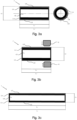
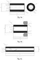
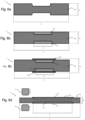
- Hot working roll ingot 1' length can be increased at high temperatures to length L V ' long enough to produce final roll 1 so, that length L V of the final roll 1 is larger than roll ingot 1' length L V ' before hot working. Additionally, with hot working it is possible to reach special material A structure and quality as well as to reach requested bond strength of special material containing part to base material containing part. Hot working can be performed for the entire length of ingot 1', like illustrated in Figures 3-5 and 8-9, or only for part of it, like illustrated in Figures 2 and 6 . If hot working is only performed for part of the roll ingot 1' , it can be performed for example only for that part of the ingot 1' that does not contain special material A, like illustrated in Figures 2 and 6 .
- the extent of hot working can be decided based on the need of the area coated with special material A to guarantee quality and bond strength.
- Figures 3 a - 3 c present one example of hot working roll ingot 1' so, that hot work item is hot isostatically pressed multimaterial starting ingot 1' that contains outer layer capsule 5 made of capsule material D like illustrated in Figure 3 a .
- hot working is performed according to Figure 3 b for the entire ingot 1' in order to increase length of finished roll 1 for requested length L V .
- Figures 4 a - 4 c illustrates another example how hot working of roll ingot 1' can be performed so that hot working is performed for multimaterial starting ingot 1' that contains interim layer 6 of interim layer material C between special material A containing part and base material B containing part.
- hot working is performed as illustrated in Figure 4 b for entire multimaterial starting ingot 1'.
- the multimaterial ingot 1' can be produced for example as illustrated in Figures 3 a- 3 c and 4 a - 4 c so, that special material A is bonded for the entire outer surface of base material B containing part so that the entire ingot length increases as multimaterial structures while in ingot cross section base material B containing part is surrounded by special material A containing part.
- special material A is possibly also in other areas of finished roll than in roll working surface 2. Consequently, in order to produce finished roll 1 it is possible to perform finish machining where special materials A can be removed for example from other surfaces than for the working surface or working surfaces 2 of finished roll 1.
- This production method is suitable for applications, where target is to coat main part of base material B containing part with special material A and/or hot working is requested to improve structure of special material A or its bond strength to base material B.
- the roll multimaterial ingot 1' can be also produced as illustrated in Figures 5 a - 5 c and 6 a - 6 c (not claimed) so that special material A has been bonded to base material B containing part of for parts of the outer surface.
- This approach one can save costs of higher quality and higher material cost special materials A and to use special materials A only in critical areas of the roll 1 like roll working surfaces.
- This allows use of hot working for the entire roll ingot 1' as for example illustrated in Figures 5 a - 5 c including special material A containing part, i.e. for example are of roll ingot 1' surrounded by special material A.
- Multimaterial ingot of roll 1 can be hot worked only partially for example as illustrated in Figures 6 a - 6 c from those areas, which does not contain special material A surrounding base material B containing part (not claimed).
- hot working of the special material A containing part during hot working of the entire ingot is beneficial for example for improving properties of special material A and/or to increase bond strength between special material A containing part and base material B containing part
- hot work special material A containing part like for example to hot work from roll ingot 1' special material A containing part addition to other areas hot work from ingot 1'.
- Figures 5 a - 5 c illustrate this method based on one example.
- combination of special material A AISI D2 and base material B DIN 42CrMo4 can be advantageously hot worked at the temperature of 1000-1200 °C.
- hot worked ingot can be transferred to furnace, which has temperature preferably at 650-750 °C, for duration of 6 hours, and consequently furnace temperature can be slowly cooled down to room temperature.
- Interim layer material C can be for example quenched and tempered steel or nickel layer.
- Capsule 5 can be sheet metal made of low carbon steel with good formability having carbon content below 0,1 weight-%. Capsule 5 can be used for example so that it covers the entire roll ingot 1' as described in Figures 9 a - 9 c . Capsule 5 thickness can be for example at least 0,5 mm or at least 1,5 mm.
- Capsule 5 can protect special material A, which due to its high alloying element content is vulnerable for cracking. This type of protection i.e. encapsulation can prevent oxidation of cracks formed into special material A and especially for special material A containing part of roll ingot 1'. It is beneficial to prevent surface oxidation of cracks because oxidation reduces or even prevents closure of cracks during hot working as hot working progresses.
- capsule 5 protects encapsulated surfaces and prevents their oxidation.
- Capsule 5 also protects special material A containing part from oxidation and decarburization reducing need for removal of decarburized layer during final machining of the roll ingot 1'.
- encapsulation may reduce need for use of special furnaces like vacuum and protective atmosphere furnaces during heat treatment which are more expensive to use than normal furnaces.
- Figures 8 a - 8 d is illustrated example to create a shaped base material B part roll ingot 1' before joining special material A containing part so, that encapsulation after work working is easier.
- a cavity is produced for base material B containing parts by machining, casting or forging to the area where special material A is joined i.e. where the special material A containing part is forms.
- Figure 8c illustrates production of special material A containing part surrounded by capsule 5.
- Figure 8 d illustrates how hot working is performed for the multimaterial starting ingot 1' described previously.
- encapsulating capsule 5 can be produced from rolled sheet metal or by using tubular capsules 5.
- the production method according to this invention allow manufacture of multimaterial roll 1 by cold or hot working. According to production process on invention a multimaterial roll 1 can be produced as one integrated component without welding and/or mechanical joint. Especially, production method according to invention is suitable to manufacture large multimaterial rolls 1 for lengths L V more than 3 meters or more than 3,5 meters or more than 4 meters.
- surface of roll ingot 1' or part of it can be encapsulated by capsule 5 before heat treatment.
- Encapsulation is always performed when using hot isostatic pressing and when special material A is powder form.
- Encapsulation can be, however, performed as previously described also to guarantee successful hot working and to minimize decarburization when using other production and joining methods for special material A.
- Interim layer 6 can be used interim layer 6 of interim layer material C between special material A part and base material B part of the roll ingot 1' to reduce detrimental interfacial reactions.
- Interim layer 6 can be installed for example to surface of base material B containing part by weld cladding, spraying or thin sheet or band.
- Base material part of roll ingot 1' is produced so that base material B is 0,15 weight-% carbon containing structural steel.
- ingot 1' is coated by hot isostatic pressing at temperature of 1100 °C and pressure of 100 MPa special material A, which is tool steel having carbon content of 1,6 weight-% total amount of carbide forming alloying elements (vanadium, molybdenum, chromium) is 15 weight-% (vanadium 9,5 weight-%, chromium 5,0 weight-% ja molybdenum 0,5 weight-%).
- special material A containing part around base material B containing part of roll ingot 1'.
- an encapsulating capsule 5 is made around base material B containing part and special material A containing part using low carbon structural steel (carbon content 0,1 weight-%), which is evacuated before hot isostatic pressing.
- the multimaterial ingot 1' is hot worked by forging after hot isostatic pressing at temperature of 1060-1200 °C for the entire length of the ingot 1' so, that the encapsulating metallic capsule 5 is maintained in the ingot during hot working. Encapsulating capsule 5 is removed after hot working by machining.
- multimaterial ingot 1' length L V ' of the roll ingot before hot working is 2 meters and diameter H V ' is 0,5 meters, and after hot working length L V ' is 5,5 meters and diameters H V ' is 0,15 meters.
- the base material B part of roll ingot 1' is produced as forging so that base material B is AISI H13 steel.
- this ingot 1' is joined by hot isostatic pressing at temperature of 1150 °C and pressure of 120 MPa special material A, which is powder metallurgical tool steel AISI M4.
- Special material A is joined only to that part of the roll ingot 1' containing base material B, which forms working surface 2 of the roll 1 after subsequently performed hot working of ingot 1'. This way is produced special material A containing part to join base material B for ingot 1'.
- the multimaterial ingot 1' produced this way is hot worked after hot isostatic pressing at temperature of 1000-1175 °C so, that both ends of the ingot 1' not coated with special material A are forged longer and special material A is not hot worked. Hot working is not performed for the part of ingot 1' containing special material A, on the contrary it is performed for other parts of roll ingot 1'.
- the length L V ' of multimaterial ingot 1' before hot working is 2 meters and diameter H V ' 0,5 meters, and after hot working length L V ' is 5,5 meters and diameter H V ' is 0,15 meters.
- Base material B containing part of roll ingot 1' is produced as steel forging so that base material B is quenched and tempered steel.
- the multimaterial ingot 1' of the roll is encapsulated by capsule 5, which is 10 mm thick structural steel containing 0,1 weight-% carbon.
- the encapsulated area is evacuated by removing the air away.
- the ingot 1' is hot worked by forging at temperature of 1050-1200 °C for the entire length including area coated with special material A.
- multimaterial ingot 1' length L V ' before hot working is 2 meters and diameter H V ' is 0,5 meters, and after hot working length L V ' is 8 meters and diameter H V ' is 0,125 meters.
- interim layer 6 For the part of roll ingot 1' base material containing part, which after hot working performed afterwards represent working surface 2 of roll 1, is formed interim layer 6 using interim layer material C as 1 mm thick nickel layer.
- multimaterial ingot 1' is hot worked by forging at 1000-1200 °C for the entire length including area coated with special material A.
- multimaterial ingot 1' length L V ' before hot working is 1,5 meters and diameter H V ' is 0,5 meters, and after hot working length L V ' is 6 meters and diameters H V ' is 0,125 meters.
- Base material B containing part of roll ingot 1' is produced as a steel forging so that base material B is carbon steel.
- Special material A containing part is produced separately using hot isostatic pressing so, that special material A is tool steel AISI D2.
- This special material A containing part is machined as a separate part for such a geometry, that it can be installed around base material B containing part of roll ingot 1'.
- This multimaterial ingot 1' is encapsulated with a capsule 5 so, that capsule is 10 mm thick structural steel with 0,1 weight-% carbon.
- encapsulated capsule is evacuated by removing air.
- the multimaterial ingot 1' length L V ' before hot working is 1,5 meters and diameter H V ' is 0,5 meters, and after hot working length L V ' is 6 meters and diameters H V ' is 0,125 meters.
- Base material B containing part of roll ingot 1' is produced as a steel forging so, that base material B is quenched and tempered steel.
- the special material part A is produced around base material containing part of roll ingot 1' so, that into the surface of base material B containing part is weld cladded by submerged arc welding a special material A which is tool steel having carbon content of 1,5 weight-% and chromium content of 15 weight-%.
- ingot 1' is hot worked by forging at temperature of 1100-1250 °C so, that hot working is performed for the weld cladded areas.
- multimaterial ingot length L V ' before hot working is 2 meters and diameter H V ' is 0,3 meters, and after hot working the length L V ' is 4.5 meters and diameter H V ' is 0,2 meters.
- Roll ingot 1' is cast in vertical position so, that
- This encapsulated roll ingot 1' is hot worked by forging at temperature of 1000-1200 °C.
- multimaterial ingot 1' length L V ' before hot working is 1,5 meters and diameter H V ' is 0,4 meters, and after hot working length L V ' is 3 meters and diameter H V ' is 0,28 meters.
- base material B is produced by spray forming and hereafter immediately before cooling of base material special material A is spray formed for part of the base material B so, that
- the encapsulated roll ingot 1' is hot worked by forging at temperature of 1000-1200 °C.
- multimaterial ingot 1' length L V ' before hot working is 1,5 meters and diameter H V ' is 0,4 meters, and after hot working length L V ' is 3 meters and diameter H V ' is 0,28 meters.
- multimaterial hot or cold working roll 1 which includes part produced of base material B, part produced of more wear resistant coating material A and possibly encapsulating capsule 5 and/or interim layer with interim layer material C between special material A and base material B.
- the method according to this invention enables manufacture of rolls containing special material A with hardness at least HRC 35 after heat treatment and carbide volume fraction at least 5 volume-%.
Landscapes
- Chemical & Material Sciences (AREA)
- Engineering & Computer Science (AREA)
- Materials Engineering (AREA)
- Mechanical Engineering (AREA)
- Manufacturing & Machinery (AREA)
- Metallurgy (AREA)
- Organic Chemistry (AREA)
- Physics & Mathematics (AREA)
- Crystallography & Structural Chemistry (AREA)
- Thermal Sciences (AREA)
- Composite Materials (AREA)
- Geometry (AREA)
- Reduction Rolling/Reduction Stand/Operation Of Reduction Machine (AREA)
- Pressure Welding/Diffusion-Bonding (AREA)
Claims (12)
- Verfahren zur Herstellung von Multimaterialrollen (1), umfassend die folgenden Schritte:- Basismaterial (B), das einen Teil des Walzbarrens (1') enthält, wird basierend auf dem gewählten Verfahren so hergestellt, dass das Basismaterial (B) ein solches eisenhaltiges Material ist, das andere Legierungselemente als Eisen mit maximal 15 Gew.-% enthält,- Spezialmaterial (A) enthaltender Teil wird mit den Basismaterial (B) enthaltenden Teilen des Walzbarrens (1') verbunden, der unter Verwendung eines geeigneten Verfahrens hergestellt wird, sodass die Dichte des Spezialmaterials (A) mindestens 90 % seiner theoretischen Dichte beträgt und es 5-40 Vol.-% des Gesamtvolumens des Basismaterials (B) und der Spezialmaterialien (A) bildet, wobei das Spezialmaterial ein legierter verschleißfester Stahl mit einem Kohlenstoffgehalt von mehr als 0,8 Gew.-% und karbidbildenden Elementen von mehr als 8 Gew.-% ist,- das Basismaterial (B) und das Spezialmaterial (A), das einen Teil des Walzbarrens (1') enthält, wird mindestens für den Teil der Länge (Lv') des Walzbarrens (1') so heiß bearbeitet, dass nach der Heißbearbeitung folgendes erreicht wird:- Die Länge (Lv) der Walze (1) ist größer als die Länge (Lv') des Walzbarrens (1') vor der Heißbearbeitung, und/oder- Der Durchmesser (Hv) der Walze (1) ist kleiner als der Durchmesser (Hv') des Walzbarrens (1') vor der Heißbearbeitung, und/oder- Der Durchmesser der Welle (3) der Walze (1) (H3) ist kleiner als der Durchmesser des Basismaterials (B) vor der Heißbearbeitung, und- Die Schichtdicke von Spezialmaterial (A) aus Multimaterial beträgt mindestens 5 mm,- dadurch gekennzeichnet, dass vor der Heißbearbeitung mindestens das Spezialmaterial (A), das Teile des Walzbarrens (1') enthält, durch eine Kapsel (5) unter Verwendung von mindestens 0,5 mm dickem Metallblech und anderen metallischen Komponenten eingekapselt wird, um die eingekapselten Teile des Walzbarrens (1') während der Heißbearbeitung zu schützen, und wobei- die Heißbearbeitung über die gesamte Länge des Walzbarrens (1') durchgeführt wird.
- Verfahren nach Anspruch 1, dadurch gekennzeichnet, dass das Spezialmaterial (A) ein auf Eisen basierendes Material ist, umfassend- Kohlenstoffgehalt von mehr als 0,8 Gew.-%,- Karbid- und nitridbildende Elemente mit mehr als 12 Gew.-%,- Volumenanteil von Karbiden und Nitriden 5-30 Vol.-%,- Härte wärmebehandelt für den endgültigen Betriebszustand mehr als HRC 35.
- Verfahren nach einem der vorstehenden Ansprüche 1 bis 2, dadurch gekennzeichnet, dass die durchschnittliche Karbidgröße im Spezialmaterial (A) kleiner als 50 µm ist.
- Verfahren nach einem der vorstehenden Ansprüche 1 bis 2, dadurch gekennzeichnet, dass die durchschnittliche Karbidgröße im Spezialmaterial (A) 1-10 µm beträgt.
- Verfahren nach einem der vorstehenden Ansprüche 1 bis 4, dadurch gekennzeichnet, dass nach der Verkapselung und vor der Heißbearbeitung des Walzbarrens (1'),- der leere Raum unter der Kapsel (5) evakuiert oder mit dem Gas gefüllt wird, und- danach wird der vorgenannte Leerraum gasdicht verschlossen, um Oxidation und/oder Entkohlung zu verhindern.
- Verfahren nach einem der vorstehenden Ansprüche 1 bis 5, wobei der das Spezialmaterial (A) enthaltende Teil mit dem das Basismaterial (B) enthaltenden Teil des Walzbarrens (1') verbunden wird, dadurch gekennzeichnet, dass zwischen diesen Materialien eine Zwischenschicht (6) angeordnet ist, die ein Zwischenschichtmaterial (C) enthält.
- Verfahren nach einem der vorstehenden Ansprüche 1 bis 6, dadurch gekennzeichnet, dass das Spezialmaterial (A), das einen Teil oder die Zwischenschicht (6) enthält, mit dem Basismaterial (B), das einen Teil des Walzbarrens (1') enthält, durch heißisostatisches Pressen, Gießen, Spritzen oder Sprühformen von geschmolzenem Metall, 3D-Druck, Schweißen oder durch ein anderes additives Herstellungsverfahren verbunden wird.
- Verfahren nach einem der vorstehenden Ansprüche 1 bis 7, dadurch gekennzeichnet, dass das Spezialmaterial (A) pulvermetallurgische Materialien sind.
- Verfahren nach bis einem der vorstehenden Ansprüche 1 bis 8, dadurch gekennzeichnet, dass das Spezialmaterial (A) enthaltende Teil des Walzbarrens (1') mit dem Basismaterial (B) enthaltenden Teil während der Herstellung des Spezialmaterials (A) verbunden wird.
- Verfahren nach einem der Ansprüche 1 bis 9, dadurch gekennzeichnet, dass das Basismaterial (B) und das Spezialmaterial (A) unter Verwendung eines additiven Herstellungsverfahrens, wie beispielsweise Spritzen von geschmolzenem Metall, Sprühformung und 3D-Druck, hergestellt werden.
- Verfahren nach einem der vorstehenden Ansprüche 1 bis 10, dadurch gekennzeichnet, dass die Heißbearbeitung durch Warmschmieden, Warmpressen oder Warmwalzen bei einer Temperatur von 800-1300 °C durchgeführt wird.
- Verfahren nach einem der vorstehenden Ansprüche 1 bis 11, dadurch gekennzeichnet, dass- die Länge (Lv) der fertigen Walze (1) mehr als 3 Meter beträgt,- Spezialmaterial (A), das einen Teil enthält, eine Beschichtung auf der äußeren Oberfläche der fertigen Walze (1) bildet, sodass diese eine Beschichtung über eine Länge von mindestens 500 mm der Gesamtlänge (Lv) der fertigen Walze (1) bildet, und- Spezialmaterial (A) eine mindestens 10 mm dicke Schicht auf mindestens 80 % des gesamten Bereichs der Beschichtung bildet.
Applications Claiming Priority (2)
| Application Number | Priority Date | Filing Date | Title |
|---|---|---|---|
| FI20197024A FI128579B (fi) | 2019-02-14 | 2019-02-14 | Menetelmä monimateriaalisen valssin valmistamiseksi ja monimateriaalivalssi |
| PCT/FI2020/000003 WO2020165489A1 (en) | 2019-02-14 | 2020-01-29 | Method for the manufacture multimaterial roll and the multimaterial roll |
Publications (3)
| Publication Number | Publication Date |
|---|---|
| EP3833496A1 EP3833496A1 (de) | 2021-06-16 |
| EP3833496A4 EP3833496A4 (de) | 2021-06-23 |
| EP3833496B1 true EP3833496B1 (de) | 2025-02-19 |
Family
ID=71993725
Family Applications (1)
| Application Number | Title | Priority Date | Filing Date |
|---|---|---|---|
| EP20756087.1A Active EP3833496B1 (de) | 2019-02-14 | 2020-01-29 | Verfahren zur herstellung von mehrmaterialrolle |
Country Status (4)
| Country | Link |
|---|---|
| US (1) | US20220032351A1 (de) |
| EP (1) | EP3833496B1 (de) |
| FI (1) | FI128579B (de) |
| WO (1) | WO2020165489A1 (de) |
Families Citing this family (3)
| Publication number | Priority date | Publication date | Assignee | Title |
|---|---|---|---|---|
| ES2900049A1 (es) * | 2020-09-15 | 2022-03-15 | Baikor Worldwide S L | Metodo de fabricacion de un componente metalico |
| EP4427277A1 (de) * | 2021-11-04 | 2024-09-11 | Matthews International GmbH | Walze zur verwendung in einem trockenbeschichtungsverfahren zur herstellung von elektroden |
| CN115194422A (zh) * | 2022-06-01 | 2022-10-18 | 中钢集团邢台机械轧辊有限公司 | 一种锻造复合轧辊的方法 |
Family Cites Families (9)
| Publication number | Priority date | Publication date | Assignee | Title |
|---|---|---|---|---|
| JPS6434360A (en) | 1987-07-31 | 1989-02-03 | Toray Industries | Improved hybrid artificial blood vessel |
| JPH0717930B2 (ja) * | 1990-06-28 | 1995-03-01 | 新日本製鐵株式会社 | 複合ロールの製造方法 |
| SE514226C2 (sv) * | 1999-04-30 | 2001-01-22 | Uddeholm Tooling Ab | Kallarbetsverktyg av stål, dess användning och tillverkning |
| US9120150B2 (en) * | 2011-12-02 | 2015-09-01 | Ati Properties, Inc. | Endplate for hot isostatic pressing canister, hot isostatic pressing canister, and hot isostatic pressing method |
| KR101642215B1 (ko) * | 2012-07-09 | 2016-07-22 | 신닛테츠스미킨 카부시키카이샤 | 복합 롤 및 압연 방법 |
| CN203284469U (zh) * | 2013-04-25 | 2013-11-13 | 马鞍山市恒泰重工机械有限公司 | 复合涂层起套辊 |
| DE102014108823B9 (de) * | 2014-06-24 | 2016-10-06 | Steinhoff Gmbh & Cie. Ohg | Walze und Verfahren zum Herstellen einer Walze zum Warm- oder Kaltwalzen von Metallflachprodukten |
| ES2873299T5 (en) * | 2015-09-08 | 2026-04-16 | Deutsche Edelstahlwerke Specialty Steel Gmbh & Co Kg | Method for producing a component having a core section made of steel |
| CN108277443B (zh) * | 2018-01-29 | 2019-12-24 | 二重(德阳)重型装备有限公司 | 4200mm以上宽厚板轧机支承辊及其制造工艺 |
-
2019
- 2019-02-14 FI FI20197024A patent/FI128579B/fi active IP Right Grant
-
2020
- 2020-01-29 EP EP20756087.1A patent/EP3833496B1/de active Active
- 2020-01-29 US US17/278,819 patent/US20220032351A1/en not_active Abandoned
- 2020-01-29 WO PCT/FI2020/000003 patent/WO2020165489A1/en not_active Ceased
Also Published As
| Publication number | Publication date |
|---|---|
| US20220032351A1 (en) | 2022-02-03 |
| EP3833496A1 (de) | 2021-06-16 |
| FI20197024A1 (fi) | 2020-08-14 |
| WO2020165489A1 (en) | 2020-08-20 |
| EP3833496A4 (de) | 2021-06-23 |
| FI128579B (fi) | 2020-08-14 |
Similar Documents
| Publication | Publication Date | Title |
|---|---|---|
| EP3833496B1 (de) | Verfahren zur herstellung von mehrmaterialrolle | |
| JP5780728B2 (ja) | 多元合金ローターセクション、それを含む溶接されたタービンローター及びその製造方法 | |
| EP2591874B1 (de) | Rührreibschweißwerkzeug aus Wolfram Karbid mit zusätzlich Nickel und mit einer Al2O3-Beschichtung | |
| FI3141335T4 (fi) | Menetelmä teräksestä valmistetun ydinosan sisältävän komponentin valmistamiseksi | |
| JP2005238334A (ja) | 金属間チタンアルミナイド合金を含有する部品または半完成品の製造方法、およびこの方法により製造し得る部品 | |
| JP4346780B2 (ja) | 耐熱耐摩耗複合構造部材およびその製造方法 | |
| US20170113274A1 (en) | Method for manufacturing a metallic component which is possible to pickle | |
| JP2012213780A (ja) | 圧延用複合ロール及びその製造方法 | |
| CN106480449A (zh) | 一种激光制造大型型材万能轧机水平辊的方法 | |
| US7284590B2 (en) | Method for manufacturing cast components | |
| JP4133078B2 (ja) | 繊維強化金属の製造方法 | |
| KR100479486B1 (ko) | 개선된 이종 금속의 접합 방법 | |
| JP2742603B2 (ja) | 混練・押出成形装置用水冷ジャケット付き多軸シリンダおよびその製造方法 | |
| JP2007131886A (ja) | 耐磨耗性に優れた繊維強化金属の製造方法 | |
| CA2358330A1 (en) | Housing for plastics, metal powder, ceramic powder or food processing machines | |
| JPH0829330B2 (ja) | 長尺小径複合ロール | |
| JPH11300461A (ja) | ダイカストマシン用スリーブ | |
| KR20170008326A (ko) | 평판 금속 제품을 열연 또는 냉연하기 위한 롤 및 롤 제조 방법 | |
| JPH11244914A (ja) | 熱間板圧延用ロール及びその製造方法 | |
| JPS627802A (ja) | 複合リング及びその製造方法 | |
| RU2722844C1 (ru) | Способ производства литой многослойной заготовки | |
| JP2787176B2 (ja) | 鋼材搬送用ローラおよびローラ本体胴部の製造方法 | |
| JPH11300459A (ja) | ダイカストマシン用スリーブ | |
| JPH0379086B2 (de) | ||
| WO2010058075A1 (en) | Method for preparing a wear-resistant multimaterial and use of the multimaterial |
Legal Events
| Date | Code | Title | Description |
|---|---|---|---|
| STAA | Information on the status of an ep patent application or granted ep patent |
Free format text: STATUS: THE INTERNATIONAL PUBLICATION HAS BEEN MADE |
|
| PUAI | Public reference made under article 153(3) epc to a published international application that has entered the european phase |
Free format text: ORIGINAL CODE: 0009012 |
|
| STAA | Information on the status of an ep patent application or granted ep patent |
Free format text: STATUS: REQUEST FOR EXAMINATION WAS MADE |
|
| STAA | Information on the status of an ep patent application or granted ep patent |
Free format text: STATUS: EXAMINATION IS IN PROGRESS |
|
| 17P | Request for examination filed |
Effective date: 20210312 |
|
| AK | Designated contracting states |
Kind code of ref document: A1 Designated state(s): AL AT BE BG CH CY CZ DE DK EE ES FI FR GB GR HR HU IE IS IT LI LT LU LV MC MK MT NL NO PL PT RO RS SE SI SK SM TR |
|
| A4 | Supplementary search report drawn up and despatched |
Effective date: 20210521 |
|
| RIC1 | Information provided on ipc code assigned before grant |
Ipc: B21B 27/02 20060101AFI20210517BHEP Ipc: B21K 1/02 20060101ALI20210517BHEP Ipc: C21B 9/00 20060101ALI20210517BHEP Ipc: B22F 3/115 20060101ALI20210517BHEP Ipc: B22F 3/15 20060101ALI20210517BHEP Ipc: B22F 10/20 20210101ALI20210517BHEP Ipc: B33Y 10/00 20150101ALI20210517BHEP Ipc: C21D 7/13 20060101ALI20210517BHEP Ipc: C22C 38/00 20060101ALI20210517BHEP Ipc: C22C 33/02 20060101ALI20210517BHEP Ipc: B22F 7/06 20060101ALN20210517BHEP Ipc: B22F 7/08 20060101ALN20210517BHEP |
|
| 17Q | First examination report despatched |
Effective date: 20210611 |
|
| DAV | Request for validation of the european patent (deleted) | ||
| DAX | Request for extension of the european patent (deleted) | ||
| RIC1 | Information provided on ipc code assigned before grant |
Ipc: B22F 7/08 20060101ALN20240424BHEP Ipc: B22F 7/06 20060101ALN20240424BHEP Ipc: B22F 10/22 20210101ALI20240424BHEP Ipc: C22C 33/02 20060101ALI20240424BHEP Ipc: C22C 38/00 20060101ALI20240424BHEP Ipc: C21D 7/13 20060101ALI20240424BHEP Ipc: B33Y 10/00 20150101ALI20240424BHEP Ipc: B22F 10/20 20210101ALI20240424BHEP Ipc: B22F 3/15 20060101ALI20240424BHEP Ipc: B22F 3/115 20060101ALI20240424BHEP Ipc: C21B 9/00 20060101ALI20240424BHEP Ipc: B21K 1/02 20060101ALI20240424BHEP Ipc: B21B 27/02 20060101AFI20240424BHEP |
|
| GRAP | Despatch of communication of intention to grant a patent |
Free format text: ORIGINAL CODE: EPIDOSNIGR1 |
|
| STAA | Information on the status of an ep patent application or granted ep patent |
Free format text: STATUS: GRANT OF PATENT IS INTENDED |
|
| RIC1 | Information provided on ipc code assigned before grant |
Ipc: B22F 7/08 20060101ALN20240508BHEP Ipc: B22F 7/06 20060101ALN20240508BHEP Ipc: B22F 10/22 20210101ALI20240508BHEP Ipc: C22C 33/02 20060101ALI20240508BHEP Ipc: C22C 38/00 20060101ALI20240508BHEP Ipc: C21D 7/13 20060101ALI20240508BHEP Ipc: B33Y 10/00 20150101ALI20240508BHEP Ipc: B22F 10/20 20210101ALI20240508BHEP Ipc: B22F 3/15 20060101ALI20240508BHEP Ipc: B22F 3/115 20060101ALI20240508BHEP Ipc: C21B 9/00 20060101ALI20240508BHEP Ipc: B21K 1/02 20060101ALI20240508BHEP Ipc: B21B 27/02 20060101AFI20240508BHEP |
|
| RIC1 | Information provided on ipc code assigned before grant |
Ipc: B22F 7/08 20060101ALN20240522BHEP Ipc: B22F 7/06 20060101ALN20240522BHEP Ipc: B22F 10/22 20210101ALI20240522BHEP Ipc: C22C 33/02 20060101ALI20240522BHEP Ipc: C22C 38/00 20060101ALI20240522BHEP Ipc: C21D 7/13 20060101ALI20240522BHEP Ipc: B33Y 10/00 20150101ALI20240522BHEP Ipc: B22F 10/20 20210101ALI20240522BHEP Ipc: B22F 3/15 20060101ALI20240522BHEP Ipc: B22F 3/115 20060101ALI20240522BHEP Ipc: C21B 9/00 20060101ALI20240522BHEP Ipc: B21K 1/02 20060101ALI20240522BHEP Ipc: B21B 27/02 20060101AFI20240522BHEP |
|
| INTG | Intention to grant announced |
Effective date: 20240605 |
|
| GRAJ | Information related to disapproval of communication of intention to grant by the applicant or resumption of examination proceedings by the epo deleted |
Free format text: ORIGINAL CODE: EPIDOSDIGR1 |
|
| STAA | Information on the status of an ep patent application or granted ep patent |
Free format text: STATUS: EXAMINATION IS IN PROGRESS |
|
| GRAS | Grant fee paid |
Free format text: ORIGINAL CODE: EPIDOSNIGR3 |
|
| STAA | Information on the status of an ep patent application or granted ep patent |
Free format text: STATUS: GRANT OF PATENT IS INTENDED |
|
| GRAP | Despatch of communication of intention to grant a patent |
Free format text: ORIGINAL CODE: EPIDOSNIGR1 |
|
| INTC | Intention to grant announced (deleted) | ||
| RIC1 | Information provided on ipc code assigned before grant |
Ipc: B22F 7/08 20060101ALN20241008BHEP Ipc: B22F 7/06 20060101ALN20241008BHEP Ipc: B22F 10/22 20210101ALI20241008BHEP Ipc: C22C 33/02 20060101ALI20241008BHEP Ipc: C22C 38/00 20060101ALI20241008BHEP Ipc: C21D 7/13 20060101ALI20241008BHEP Ipc: B33Y 10/00 20150101ALI20241008BHEP Ipc: B22F 10/20 20210101ALI20241008BHEP Ipc: B22F 3/15 20060101ALI20241008BHEP Ipc: B22F 3/115 20060101ALI20241008BHEP Ipc: C21B 9/00 20060101ALI20241008BHEP Ipc: B21K 1/02 20060101ALI20241008BHEP Ipc: B21B 27/02 20060101AFI20241008BHEP |
|
| INTG | Intention to grant announced |
Effective date: 20241021 |
|
| GRAA | (expected) grant |
Free format text: ORIGINAL CODE: 0009210 |
|
| STAA | Information on the status of an ep patent application or granted ep patent |
Free format text: STATUS: THE PATENT HAS BEEN GRANTED |
|
| AK | Designated contracting states |
Kind code of ref document: B1 Designated state(s): AL AT BE BG CH CY CZ DE DK EE ES FI FR GB GR HR HU IE IS IT LI LT LU LV MC MK MT NL NO PL PT RO RS SE SI SK SM TR |
|
| REG | Reference to a national code |
Ref country code: GB Ref legal event code: FG4D |
|
| REG | Reference to a national code |
Ref country code: CH Ref legal event code: EP |
|
| REG | Reference to a national code |
Ref country code: IE Ref legal event code: FG4D |
|
| REG | Reference to a national code |
Ref country code: DE Ref legal event code: R096 Ref document number: 602020046331 Country of ref document: DE |
|
| REG | Reference to a national code |
Ref country code: NL Ref legal event code: MP Effective date: 20250219 |
|
| PG25 | Lapsed in a contracting state [announced via postgrant information from national office to epo] |
Ref country code: RS Free format text: LAPSE BECAUSE OF FAILURE TO SUBMIT A TRANSLATION OF THE DESCRIPTION OR TO PAY THE FEE WITHIN THE PRESCRIBED TIME-LIMIT Effective date: 20250519 |
|
| PG25 | Lapsed in a contracting state [announced via postgrant information from national office to epo] |
Ref country code: FI Free format text: LAPSE BECAUSE OF FAILURE TO SUBMIT A TRANSLATION OF THE DESCRIPTION OR TO PAY THE FEE WITHIN THE PRESCRIBED TIME-LIMIT Effective date: 20250219 |
|
| PG25 | Lapsed in a contracting state [announced via postgrant information from national office to epo] |
Ref country code: PL Free format text: LAPSE BECAUSE OF FAILURE TO SUBMIT A TRANSLATION OF THE DESCRIPTION OR TO PAY THE FEE WITHIN THE PRESCRIBED TIME-LIMIT Effective date: 20250219 |
|
| PG25 | Lapsed in a contracting state [announced via postgrant information from national office to epo] |
Ref country code: ES Free format text: LAPSE BECAUSE OF FAILURE TO SUBMIT A TRANSLATION OF THE DESCRIPTION OR TO PAY THE FEE WITHIN THE PRESCRIBED TIME-LIMIT Effective date: 20250219 |
|
| REG | Reference to a national code |
Ref country code: LT Ref legal event code: MG9D |
|
| PG25 | Lapsed in a contracting state [announced via postgrant information from national office to epo] |
Ref country code: NO Free format text: LAPSE BECAUSE OF FAILURE TO SUBMIT A TRANSLATION OF THE DESCRIPTION OR TO PAY THE FEE WITHIN THE PRESCRIBED TIME-LIMIT Effective date: 20250519 Ref country code: IS Free format text: LAPSE BECAUSE OF FAILURE TO SUBMIT A TRANSLATION OF THE DESCRIPTION OR TO PAY THE FEE WITHIN THE PRESCRIBED TIME-LIMIT Effective date: 20250619 |
|
| PG25 | Lapsed in a contracting state [announced via postgrant information from national office to epo] |
Ref country code: NL Free format text: LAPSE BECAUSE OF FAILURE TO SUBMIT A TRANSLATION OF THE DESCRIPTION OR TO PAY THE FEE WITHIN THE PRESCRIBED TIME-LIMIT Effective date: 20250219 |
|
| PG25 | Lapsed in a contracting state [announced via postgrant information from national office to epo] |
Ref country code: HR Free format text: LAPSE BECAUSE OF FAILURE TO SUBMIT A TRANSLATION OF THE DESCRIPTION OR TO PAY THE FEE WITHIN THE PRESCRIBED TIME-LIMIT Effective date: 20250219 |
|
| PG25 | Lapsed in a contracting state [announced via postgrant information from national office to epo] |
Ref country code: PT Free format text: LAPSE BECAUSE OF FAILURE TO SUBMIT A TRANSLATION OF THE DESCRIPTION OR TO PAY THE FEE WITHIN THE PRESCRIBED TIME-LIMIT Effective date: 20250620 Ref country code: LV Free format text: LAPSE BECAUSE OF FAILURE TO SUBMIT A TRANSLATION OF THE DESCRIPTION OR TO PAY THE FEE WITHIN THE PRESCRIBED TIME-LIMIT Effective date: 20250219 |
|
| PG25 | Lapsed in a contracting state [announced via postgrant information from national office to epo] |
Ref country code: GR Free format text: LAPSE BECAUSE OF FAILURE TO SUBMIT A TRANSLATION OF THE DESCRIPTION OR TO PAY THE FEE WITHIN THE PRESCRIBED TIME-LIMIT Effective date: 20250520 Ref country code: BG Free format text: LAPSE BECAUSE OF FAILURE TO SUBMIT A TRANSLATION OF THE DESCRIPTION OR TO PAY THE FEE WITHIN THE PRESCRIBED TIME-LIMIT Effective date: 20250219 |
|
| REG | Reference to a national code |
Ref country code: AT Ref legal event code: MK05 Ref document number: 1767823 Country of ref document: AT Kind code of ref document: T Effective date: 20250219 |
|
| PG25 | Lapsed in a contracting state [announced via postgrant information from national office to epo] |
Ref country code: SE Free format text: LAPSE BECAUSE OF FAILURE TO SUBMIT A TRANSLATION OF THE DESCRIPTION OR TO PAY THE FEE WITHIN THE PRESCRIBED TIME-LIMIT Effective date: 20250219 |
|
| PG25 | Lapsed in a contracting state [announced via postgrant information from national office to epo] |
Ref country code: SM Free format text: LAPSE BECAUSE OF FAILURE TO SUBMIT A TRANSLATION OF THE DESCRIPTION OR TO PAY THE FEE WITHIN THE PRESCRIBED TIME-LIMIT Effective date: 20250219 |
|
| PG25 | Lapsed in a contracting state [announced via postgrant information from national office to epo] |
Ref country code: DK Free format text: LAPSE BECAUSE OF FAILURE TO SUBMIT A TRANSLATION OF THE DESCRIPTION OR TO PAY THE FEE WITHIN THE PRESCRIBED TIME-LIMIT Effective date: 20250219 |
|
| PG25 | Lapsed in a contracting state [announced via postgrant information from national office to epo] |
Ref country code: IT Free format text: LAPSE BECAUSE OF FAILURE TO SUBMIT A TRANSLATION OF THE DESCRIPTION OR TO PAY THE FEE WITHIN THE PRESCRIBED TIME-LIMIT Effective date: 20250219 |
|
| PG25 | Lapsed in a contracting state [announced via postgrant information from national office to epo] |
Ref country code: AT Free format text: LAPSE BECAUSE OF FAILURE TO SUBMIT A TRANSLATION OF THE DESCRIPTION OR TO PAY THE FEE WITHIN THE PRESCRIBED TIME-LIMIT Effective date: 20250219 |
|
| PG25 | Lapsed in a contracting state [announced via postgrant information from national office to epo] |
Ref country code: EE Free format text: LAPSE BECAUSE OF FAILURE TO SUBMIT A TRANSLATION OF THE DESCRIPTION OR TO PAY THE FEE WITHIN THE PRESCRIBED TIME-LIMIT Effective date: 20250219 Ref country code: CZ Free format text: LAPSE BECAUSE OF FAILURE TO SUBMIT A TRANSLATION OF THE DESCRIPTION OR TO PAY THE FEE WITHIN THE PRESCRIBED TIME-LIMIT Effective date: 20250219 |
|
| PG25 | Lapsed in a contracting state [announced via postgrant information from national office to epo] |
Ref country code: RO Free format text: LAPSE BECAUSE OF FAILURE TO SUBMIT A TRANSLATION OF THE DESCRIPTION OR TO PAY THE FEE WITHIN THE PRESCRIBED TIME-LIMIT Effective date: 20250219 |
|
| PG25 | Lapsed in a contracting state [announced via postgrant information from national office to epo] |
Ref country code: SK Free format text: LAPSE BECAUSE OF FAILURE TO SUBMIT A TRANSLATION OF THE DESCRIPTION OR TO PAY THE FEE WITHIN THE PRESCRIBED TIME-LIMIT Effective date: 20250219 |
|
| REG | Reference to a national code |
Ref country code: DE Ref legal event code: R097 Ref document number: 602020046331 Country of ref document: DE |
|
| PLBE | No opposition filed within time limit |
Free format text: ORIGINAL CODE: 0009261 |
|
| STAA | Information on the status of an ep patent application or granted ep patent |
Free format text: STATUS: NO OPPOSITION FILED WITHIN TIME LIMIT |
|
| 26N | No opposition filed |
Effective date: 20251120 |
|
| PGFP | Annual fee paid to national office [announced via postgrant information from national office to epo] |
Ref country code: GB Payment date: 20260121 Year of fee payment: 7 |
|
| PGFP | Annual fee paid to national office [announced via postgrant information from national office to epo] |
Ref country code: DE Payment date: 20260122 Year of fee payment: 7 |
|
| PGFP | Annual fee paid to national office [announced via postgrant information from national office to epo] |
Ref country code: FR Payment date: 20260120 Year of fee payment: 7 |