EP3833525B1 - Dispositif à canaux chauffants - Google Patents
Dispositif à canaux chauffants Download PDFInfo
- Publication number
- EP3833525B1 EP3833525B1 EP19749697.9A EP19749697A EP3833525B1 EP 3833525 B1 EP3833525 B1 EP 3833525B1 EP 19749697 A EP19749697 A EP 19749697A EP 3833525 B1 EP3833525 B1 EP 3833525B1
- Authority
- EP
- European Patent Office
- Prior art keywords
- hot runner
- data
- memory
- process data
- runner device
- Prior art date
- Legal status (The legal status is an assumption and is not a legal conclusion. Google has not performed a legal analysis and makes no representation as to the accuracy of the status listed.)
- Active
Links
Images

Classifications
-
- B—PERFORMING OPERATIONS; TRANSPORTING
- B29—WORKING OF PLASTICS; WORKING OF SUBSTANCES IN A PLASTIC STATE IN GENERAL
- B29C—SHAPING OR JOINING OF PLASTICS; SHAPING OF MATERIAL IN A PLASTIC STATE, NOT OTHERWISE PROVIDED FOR; AFTER-TREATMENT OF THE SHAPED PRODUCTS, e.g. REPAIRING
- B29C45/00—Injection moulding, i.e. forcing the required volume of moulding material through a nozzle into a closed mould; Apparatus therefor
- B29C45/17—Component parts, details or accessories; Auxiliary operations
- B29C45/76—Measuring, controlling or regulating
- B29C45/77—Measuring, controlling or regulating of velocity or pressure of moulding material
-
- B—PERFORMING OPERATIONS; TRANSPORTING
- B29—WORKING OF PLASTICS; WORKING OF SUBSTANCES IN A PLASTIC STATE IN GENERAL
- B29C—SHAPING OR JOINING OF PLASTICS; SHAPING OF MATERIAL IN A PLASTIC STATE, NOT OTHERWISE PROVIDED FOR; AFTER-TREATMENT OF THE SHAPED PRODUCTS, e.g. REPAIRING
- B29C45/00—Injection moulding, i.e. forcing the required volume of moulding material through a nozzle into a closed mould; Apparatus therefor
- B29C45/17—Component parts, details or accessories; Auxiliary operations
- B29C45/26—Moulds
- B29C45/27—Sprue channels ; Runner channels or runner nozzles
-
- B—PERFORMING OPERATIONS; TRANSPORTING
- B29—WORKING OF PLASTICS; WORKING OF SUBSTANCES IN A PLASTIC STATE IN GENERAL
- B29C—SHAPING OR JOINING OF PLASTICS; SHAPING OF MATERIAL IN A PLASTIC STATE, NOT OTHERWISE PROVIDED FOR; AFTER-TREATMENT OF THE SHAPED PRODUCTS, e.g. REPAIRING
- B29C45/00—Injection moulding, i.e. forcing the required volume of moulding material through a nozzle into a closed mould; Apparatus therefor
- B29C45/17—Component parts, details or accessories; Auxiliary operations
- B29C45/76—Measuring, controlling or regulating
- B29C45/78—Measuring, controlling or regulating of temperature
-
- B—PERFORMING OPERATIONS; TRANSPORTING
- B29—WORKING OF PLASTICS; WORKING OF SUBSTANCES IN A PLASTIC STATE IN GENERAL
- B29C—SHAPING OR JOINING OF PLASTICS; SHAPING OF MATERIAL IN A PLASTIC STATE, NOT OTHERWISE PROVIDED FOR; AFTER-TREATMENT OF THE SHAPED PRODUCTS, e.g. REPAIRING
- B29C2945/00—Indexing scheme relating to injection moulding, i.e. forcing the required volume of moulding material through a nozzle into a closed mould
- B29C2945/76—Measuring, controlling or regulating
- B29C2945/76003—Measured parameter
- B29C2945/76006—Pressure
-
- B—PERFORMING OPERATIONS; TRANSPORTING
- B29—WORKING OF PLASTICS; WORKING OF SUBSTANCES IN A PLASTIC STATE IN GENERAL
- B29C—SHAPING OR JOINING OF PLASTICS; SHAPING OF MATERIAL IN A PLASTIC STATE, NOT OTHERWISE PROVIDED FOR; AFTER-TREATMENT OF THE SHAPED PRODUCTS, e.g. REPAIRING
- B29C2945/00—Indexing scheme relating to injection moulding, i.e. forcing the required volume of moulding material through a nozzle into a closed mould
- B29C2945/76—Measuring, controlling or regulating
- B29C2945/76003—Measured parameter
- B29C2945/7604—Temperature
-
- B—PERFORMING OPERATIONS; TRANSPORTING
- B29—WORKING OF PLASTICS; WORKING OF SUBSTANCES IN A PLASTIC STATE IN GENERAL
- B29C—SHAPING OR JOINING OF PLASTICS; SHAPING OF MATERIAL IN A PLASTIC STATE, NOT OTHERWISE PROVIDED FOR; AFTER-TREATMENT OF THE SHAPED PRODUCTS, e.g. REPAIRING
- B29C2945/00—Indexing scheme relating to injection moulding, i.e. forcing the required volume of moulding material through a nozzle into a closed mould
- B29C2945/76—Measuring, controlling or regulating
- B29C2945/76177—Location of measurement
- B29C2945/76254—Mould
- B29C2945/76274—Mould runners, nozzles
- B29C2945/7628—Mould runners, nozzles manifolds
-
- B—PERFORMING OPERATIONS; TRANSPORTING
- B29—WORKING OF PLASTICS; WORKING OF SUBSTANCES IN A PLASTIC STATE IN GENERAL
- B29C—SHAPING OR JOINING OF PLASTICS; SHAPING OF MATERIAL IN A PLASTIC STATE, NOT OTHERWISE PROVIDED FOR; AFTER-TREATMENT OF THE SHAPED PRODUCTS, e.g. REPAIRING
- B29C2945/00—Indexing scheme relating to injection moulding, i.e. forcing the required volume of moulding material through a nozzle into a closed mould
- B29C2945/76—Measuring, controlling or regulating
- B29C2945/76344—Phase or stage of measurement
- B29C2945/76381—Injection
-
- B—PERFORMING OPERATIONS; TRANSPORTING
- B29—WORKING OF PLASTICS; WORKING OF SUBSTANCES IN A PLASTIC STATE IN GENERAL
- B29C—SHAPING OR JOINING OF PLASTICS; SHAPING OF MATERIAL IN A PLASTIC STATE, NOT OTHERWISE PROVIDED FOR; AFTER-TREATMENT OF THE SHAPED PRODUCTS, e.g. REPAIRING
- B29C2945/00—Indexing scheme relating to injection moulding, i.e. forcing the required volume of moulding material through a nozzle into a closed mould
- B29C2945/76—Measuring, controlling or regulating
- B29C2945/76451—Measurement means
-
- B—PERFORMING OPERATIONS; TRANSPORTING
- B29—WORKING OF PLASTICS; WORKING OF SUBSTANCES IN A PLASTIC STATE IN GENERAL
- B29C—SHAPING OR JOINING OF PLASTICS; SHAPING OF MATERIAL IN A PLASTIC STATE, NOT OTHERWISE PROVIDED FOR; AFTER-TREATMENT OF THE SHAPED PRODUCTS, e.g. REPAIRING
- B29C2945/00—Indexing scheme relating to injection moulding, i.e. forcing the required volume of moulding material through a nozzle into a closed mould
- B29C2945/76—Measuring, controlling or regulating
- B29C2945/76494—Controlled parameter
- B29C2945/76498—Pressure
-
- B—PERFORMING OPERATIONS; TRANSPORTING
- B29—WORKING OF PLASTICS; WORKING OF SUBSTANCES IN A PLASTIC STATE IN GENERAL
- B29C—SHAPING OR JOINING OF PLASTICS; SHAPING OF MATERIAL IN A PLASTIC STATE, NOT OTHERWISE PROVIDED FOR; AFTER-TREATMENT OF THE SHAPED PRODUCTS, e.g. REPAIRING
- B29C2945/00—Indexing scheme relating to injection moulding, i.e. forcing the required volume of moulding material through a nozzle into a closed mould
- B29C2945/76—Measuring, controlling or regulating
- B29C2945/76494—Controlled parameter
- B29C2945/76531—Temperature
-
- B—PERFORMING OPERATIONS; TRANSPORTING
- B29—WORKING OF PLASTICS; WORKING OF SUBSTANCES IN A PLASTIC STATE IN GENERAL
- B29C—SHAPING OR JOINING OF PLASTICS; SHAPING OF MATERIAL IN A PLASTIC STATE, NOT OTHERWISE PROVIDED FOR; AFTER-TREATMENT OF THE SHAPED PRODUCTS, e.g. REPAIRING
- B29C2945/00—Indexing scheme relating to injection moulding, i.e. forcing the required volume of moulding material through a nozzle into a closed mould
- B29C2945/76—Measuring, controlling or regulating
- B29C2945/76655—Location of control
- B29C2945/76732—Mould
- B29C2945/76752—Mould runners, nozzles
-
- B—PERFORMING OPERATIONS; TRANSPORTING
- B29—WORKING OF PLASTICS; WORKING OF SUBSTANCES IN A PLASTIC STATE IN GENERAL
- B29C—SHAPING OR JOINING OF PLASTICS; SHAPING OF MATERIAL IN A PLASTIC STATE, NOT OTHERWISE PROVIDED FOR; AFTER-TREATMENT OF THE SHAPED PRODUCTS, e.g. REPAIRING
- B29C2945/00—Indexing scheme relating to injection moulding, i.e. forcing the required volume of moulding material through a nozzle into a closed mould
- B29C2945/76—Measuring, controlling or regulating
- B29C2945/76929—Controlling method
- B29C2945/76939—Using stored or historical data sets
-
- B—PERFORMING OPERATIONS; TRANSPORTING
- B29—WORKING OF PLASTICS; WORKING OF SUBSTANCES IN A PLASTIC STATE IN GENERAL
- B29C—SHAPING OR JOINING OF PLASTICS; SHAPING OF MATERIAL IN A PLASTIC STATE, NOT OTHERWISE PROVIDED FOR; AFTER-TREATMENT OF THE SHAPED PRODUCTS, e.g. REPAIRING
- B29C45/00—Injection moulding, i.e. forcing the required volume of moulding material through a nozzle into a closed mould; Apparatus therefor
- B29C45/17—Component parts, details or accessories; Auxiliary operations
- B29C45/26—Moulds
- B29C45/27—Sprue channels ; Runner channels or runner nozzles
- B29C45/2725—Manifolds
Definitions
- the invention relates to a hot runner device according to the preamble of claim 1.
- a hot runner device forms part of an injection molding machine, which has as components at least one plasticizing unit - which can be designed, for example, as an extruder - and an openable and re-closable tool.
- the tool in turn also has a first tool half and a second tool half.
- a heated hot runner system is installed in one half of the tool.
- the hot runner system has the task of directing pressurized melt at a temperature above the glass transition or crystallite melting temperature through a distributor and nozzle system into one or more cavities of the tool. It can have a nozzle, a distributor and a sprue bushing as well as possibly other components as components.
- a hot runner device in the sense of this document has such a hot runner system for passing hot melt through and also has electrical and / or electronic components that can be connected or connected via a control and regulating device of the hot runner device to a central, higher-level control and regulating device of the injection molding machine Operation are also connected, which controls and / or regulates the entire injection molding process.
- the electrical and/or electronic components of the hot runner device include one or more sensors. These components also generally include at least one temperature control circuit, consisting of at least one heater and at least one temperature probe or sensor.
- the components nozzle, distributor and sprue bushing are tempered using the heaters, with heating zones being formed.
- Each individual heating zone can be controlled separately.
- the temperatures for each heating zone are recorded using a suitable temperature measurement method (e.g. thermocouple and/or thermal sensor) and then serve as an input or controlled variable for the control and/or regulating device of the hot runner device.
- hot runner device within the tool half, which contains the hot runner system and components assigned to it - i.e. hot runner technology - (here also called hot runner device) - connecting cables for the heaters and the thermal sensors are brought together in a wiring box to form at least one plug.
- the hot runner device is connected to the control and regulation device of the hot runner device using additional plugs and cables.
- the technological background is: DE112008001188 and the DE 102013012914 called.
- the DE112008001188 discloses an injection molding machine that has a control and regulation device that includes a memory device that is connected to a hot runner distributor and stores information that is used to transmit process data and signals to the control and / or regulating device of the injection molding machine.
- a first control device which receives signals from a hot runner system and forwards them to a higher-level second control device.
- a sensor is arranged on the hot runner system, but this sensor is used exclusively to control the hot runner system.
- the unit provided for control is a higher-level control and regulation device within the meaning of the preamble of claim 1.
- the invention has the task of further optimizing the generic prior art in order to achieve improved monitoring of the operation of the machine.
- the invention solves this problem by the device of claim 1, the injection molding machine of claim 10 and the method of claim 11.
- Advantageous refinements can be found in the subclaims.
- a hot runner device is created for an injection molding machine, with a control and regulating device of the hot runner device, the hot runner device further having at least one hot runner system, as well as at least one sensor, actuator and / or initiator, which has one or more signal and / or data paths , in particular lines, can be connected to a higher-level control and regulation device, process data and/or signals being transferable via the one or more signal and/or data paths, characterized in that the hot runner device further comprises a data acquisition and backup device which at least for detecting and storing part or all of the hot runner system during operation of the injection molding machine recorded process data and/or signals and which is functional is an integral part of the hot runner device and that the data acquisition and backup device has at least one measured value acquisition device connected to the at least one sensor, actuator and / or initiator and at least one storage and analysis device connected to the measured value acquisition device, the storage and analysis device having its own computer unit which has a microprocessor unit and a data memory and wherein the data acquisition and data
- process data about the operating state of the hot runner device was stored on a device that is functionally directly assigned to the hot runner device.
- control and regulating device is the hot runner device and that it can be connected to a further, central, higher-level control and regulating device of the injection molding machine - which is not part of the hot runner device - or is connected during operation , with which data and/or signals can preferably be exchanged bidirectionally.
- the one or more data routes is/are designed as electrical or optical lines or wireless routes and that the data acquisition and backup device is connected to or with these electrical and/or optical lines or routes are connected to enable the data acquisition and backup device to access the necessary signals and information, which it then stores as process data.
- the data acquisition and backup device has at least one measured value acquisition device connected to the at least one sensor, actuator and / or initiator and at least one to the measured value acquisition device connected storage and analysis facility. In this way, the two tasks of measuring measured values and parameter recording on the one hand and storage on the other can be functionally easily separated and implemented.
- the hot runner system has at least one nozzle, at least one distributor and at least one sprue bushing as mechanical structural components.
- the storage and analysis device can also be divided into two functional devices, i.e. a storage device and an analysis device. This also falls under the term storage and analysis device.
- the data cloud can take over the tasks of the data backup device or the role of the storage device of the storage and analysis device. Only one interface is then necessary for bidirectional transmission to/from the cloud. It can then also be provided that the hot runner device 14 has a code/an identifier/an IP address so that the data in the cloud can be clearly assigned.
- the analysis device can - if the data is stored in the data cloud - be provided directly on the hot runner system or, if necessary, elsewhere.
- a computer unit can also be provided directly on the measured value acquisition device, which is designed to be able to store the data in the data cloud and/or to be able to analyze it.
- the storage takes place in a non-volatile memory in such a way that the process data can be read out again later even after a power failure.
- process data recorded with the measured value acquisition unit is stored in the storage and analysis device in a simple manner at time intervals.
- an analysis of the process data takes place in the storage and analysis device.
- Temperature data and/or pressure data and/or cycle data and/or process data on needle positions, speeds and strokes can be stored in the storage and analysis device as process data.
- Fig. 1 shows a schematic representation of an injection molding machine 100, which has as components a plasticizing unit 200 for plasticizing melt - which can be designed, for example, as an extruder, and an openable and closable tool 300.
- a plasticizing unit 200 for plasticizing melt - which can be designed, for example, as an extruder, and an openable and closable tool 300.
- the tool 300 has two tool halves 310 and 320.
- the tool half 310 is also referred to here synonymously as the hot runner system 11 (see Fig. 3 ) or has one.
- the hot runner system 11 is part of a hot runner device 14.
- the hot runner device has the hot runner system 11 as well as electrical and/or electronic components (see also Fig. 2a, b and 3 ).
- the hot runner system 11 - as explained at the beginning of the prior art - has the task of feeding pressurized melt at a temperature above the glass transition or crystallite melting temperature through a distributor and nozzle system (here Fig. 1 ) into one or more cavities of the tool. It can have as components at least one nozzle 311, at least one distributor (integrated in frame plate 312) and at least one sprue bushing (integrated in frame plate 312) and possibly other machine elements or components.
- the hot runner device 14 with the hot runner system 11 also has electrical and/or electronic components, which are connected here to a higher-level control and regulation device 13 of the hot runner device 14, which control all hot runner parameters (e.g. temperatures) and/or the entire injection molding process and/ or can regulate.
- the control and regulation device is symbolically represented here by a control cabinet 111.
- the control cabinet 112 here also contains, among other things, a further, central control and regulation device of the injection molding machine, the latter control and regulation device of the injection molding machine being able to exchange data with the control and regulation device 13 of the hot runner device 14 for hot runner control.
- the components nozzles 311, distributor (integrated in frame plate 312) and sprue bushing(s) (integrated in frame plate 312) are tempered by means of heaters, with heating zones being formed. Each individual heating zone is regulated separately. For this purpose, the temperatures per heating zone are recorded using a suitable temperature measurement method (e.g. thermocouple and/or thermal sensor 313) and then serve as an input or controlled variable for the control and/or regulating device 13 of the hot runner device 14.
- a suitable temperature measurement method e.g. thermocouple and/or thermal sensor 313
- Needle drives 314 for the nozzles 311 can also be integrated in the hot runner system 11 of the hot runner device 14. Each individual needle drive 314 is controlled separately, with the needle drive transmitting an electrical variable to the control and/or regulating device 13 of the hot runner device 14.
- the tool half which contains the hot runner system and components associated with it - i.e. preferably the complete hot runner technology (the so-called hot side, here also called the hot runner device) - connecting cables for the heaters and the thermal sensors are in a wiring box to form at least one plug 12 (see also Fig. 2 ) merged.
- the hot runner device 14 is connected to the higher-level control and regulation device 13 of the hot runner device 14.
- the hot runner device 14 - of the invention - also has at least one data acquisition and data backup device that is directly, at least functionally, associated with it. This is provided in addition to the higher-level control and regulation device 13 of the hot runner device 14 and is functionally independent of it. It therefore cannot be connected to this.
- the data acquisition and data backup device can also be directly assigned locally to the hot runner device 14.
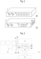
- This data acquisition and data backup device has a measured value acquisition device 1 and a storage and analysis device 2 (see Fig.1 and 2 ).
- the measured value acquisition device 1 and the storage and analysis device 2 can also be designed as an integrated box.
- the hot runner device 14 also has various lines or cables 15a, b, c, d; 16a, b, c, d and at least one plug as an external interface 12 (see Fig. 1 , 2a, b and 3 ).
- the higher-level control and regulation device 13 of the hot runner device 14 can be connected to the interface 12 and is also connected during operation.
- Lines 15a, b, c, d, ... are shown. These lines 15a, b, c, d, ... symbolize one or more signal and/or data path(s), in particular an electrical or optical or wireless connection between sensors, actuators and/or initiators and the like of the hot runner system 11 on the one hand and here the interface 12 on the other hand.
- the sensors, actuators and/or initiators of the hot runner system 11 is or are connected directly via the interface 12 to the higher-level control and regulation device 13 of the hot runner device.
- the measured value acquisition device 1 is also connected to the sensors, actuators and/or initiators of the hot runner system, in particular for monitoring at least one process parameter of the injection molding process.
- the measured value acquisition device 1 can thus be connected to the sensors, actuators and/or initiators via branch lines 16a, 16b, 16c, 16d on the line(s) 15a, b, c, d or cables or in another way, for example wirelessly.
- the data acquisition and data backup device of the hot runner device is designed to record, record, store and/or analyze process data directly from the hot runner system 11, independently of the higher-level control and regulation device 13 of the hot runner device 14.
- the data acquisition and backup device has at least the components of the measured value acquisition device 1 and the storage and analysis device 2.
- the last-mentioned device has an independent computer unit which has a microprocessor unit and a data memory.
- signals and process data are recorded during operation, in particular operating process signals and data of the hot runner system 11 and / or measured values from the hot runner system 11, which are thus, for example, in a simple manner on the lines or cables 15a-d that are to be provided anyway (e.g. thermal sensor cable and/or power cables for the heaters) can be tapped within the hot side.
- no additional installations, e.g. thermal sensors, are necessary to record the data in the data acquisition and backup device. Tapping the signals on the existing connecting cables is sufficient for recording and monitoring.
- process data and measured values are then sent to the storage and analysis device 2, where they are stored and can optionally be further processed there.
- the storage and analysis device 2 can be provided with a computer program that carries out the data storage and, if necessary, also analyzes the process data, for example in order to detect and, if necessary, display errors in the operation of the hot runner device 14.
- the corresponding process data is thus stored in an element or means that is functionally directly attributable to the hot runner device 14 - the storage and analysis device 2.
- This storage is preferably carried out in a non-volatile memory in such a way that the process data can be read out again later even after a power failure.
- process data which reflect the course of the process
- the hot runner device 14 it is possible to store process data, which reflect the course of the process, directly on the hot runner device 14, so that they can be called up again, for example after a malfunction, regardless of any additional storage on the central control and regulation unit 112, 113.
- the course of the process can be recorded over the entire life cycle, even if the hot runner device 14 is used on different injection molding machines and/or is regulated and/or controlled by different control and regulating devices 13.
- the measured value recording device 1 can be equipped with at least one analog input 5 - in particular a thermal sensor measuring input, as well as with at least one analog/digital converter and at least one measuring amplifier. In this way, a measured value can be recorded at least with a corresponding sensor and converted into at least one digital value.
- the measured value e.g. a voltage signal or a current signal
- is displayed directly on the Hot runner system 11 is tapped on lines already provided according to the prior art for, for example, the thermal sensors, which are located in the nozzles, distributor and sprue bushing, and fed to the measured value recording device 1.
- This measured value acquisition device 1 can also have both an input interface 3 and an output interface 4 for data transmission. Several measured value acquisition devices 1 can also be connected in series in order to be able to record a large number of process data.
- the measured value acquisition device 1 can be connected to the storage and analysis device 2 via a cable 17.
- the incoming process data is stored permanently in the provided, particularly internal, memory, in particular at a regular time interval (e.g. every 10 seconds).
- the stored process data can preferably be accessed via a wide variety of interfaces 8, 9 (e.g. USB, WiFi, Ethernet, Bluetooth). These can be intelligently visualized and evaluated in various ways.
- interfaces 8, 9 e.g. USB, WiFi, Ethernet, Bluetooth.
- the storage and analysis device 2 can in particular also be designed to give an alarm in the event of deviations from previously set values. This can include warnings being passed on in various forms (e.g. via email or system information) to different recipients.
- Machine process data or analyzes can be displayed on a display device 113 of the injection molding machine. This machine process data is transmitted from the injection molding machine control 112 to the display device 113. In the event of a malfunction, it is possible with the storage and analysis device 2 to compare the process data of the hot runner system with the machine process data of the injection molding machine control, which also processes data from the open-loop and closed-loop control device 13. In this way it is possible to determine whether the process data from the hot runner deviates from the machine process data. From this comparison it can be determined whether the error lies in the hot runner device 14 or whether the error lies in the control and regulating device 13 or in the injection molding machine control 112.
- the data acquisition and data backup device - in particular its storage and analysis device 2 - is a direct functional part of the hot runner device 14 and is independent of other connected devices, such as a control and regulating device 13 of the hot runner device 14. This offers the advantage of unadulterated conclusions about the process in to be able to pull the entire hot runner system 11.
- a control and regulating device of the injection molding machine is additionally provided on it.
Landscapes
- Engineering & Computer Science (AREA)
- Manufacturing & Machinery (AREA)
- Mechanical Engineering (AREA)
- Injection Moulding Of Plastics Or The Like (AREA)
- Moulds For Moulding Plastics Or The Like (AREA)
Claims (15)
- Dispositif de canaux chauffants (14) pour une machine de moulage par injection, muni d'un dispositif de commande et de régulation (13) pour le dispositif de canaux chauffants (14), lequel dispositif de canaux chauffants comprend en outre au moins un circuit de canaux chauffants (11) et au moins un capteur, un actionneur et/ou un commutateur, qui peut/peuvent être connecté/s par un ou plusieurs trajets de signal et/ou de données, en particulier des lignes, avec une installation de commande et de régulation de niveau supérieur, des données et/ou signaux de process pouvant être transmis par le ou les plusieurs trajets de signal et/ou de données, le dispositif de canaux chauffants comprenant en outre une installation d'acquisition et de sauvegarde de données (1, 2) qui est dimensionnée au moins pour acquérir et sauvegarder une partie ou l'intégralité des données et/ou signaux de process acquises pendant le fonctionnement de la machine de moulage par injection au niveau du circuit de canaux chauffants (11) et qui fait partie intégrante, du point de vue fonctionnel, du dispositif de canaux chauffants (14), caractérisé en ce que l'installation d'acquisition et de sauvegarde de données (1, 2) comporte au moins une installation d'acquisition de valeurs de mesure (1) connectée à au moins un capteur, actionneur et/ou commutateur et au moins une installation d'enregistrement et d'analyse (1) connectée à l'installation d'acquisition de données de mesure (1), l'installation d'enregistrement et d'analyse (2) comportant une unité de calculateur propre qui comprend une unité de microprocesseur et une mémoire de données et l'installation d'acquisition et de sauvegarde de données (1, 2) du dispositif de canaux chauffants étant dimensionnée pour capter ou acquérir des données et/ou signaux de process directement sur le circuit de canaux chauffants (11), les enregistrer et/ou les analyser indépendamment du dispositif de commande et de régulation (13) du dispositif de canaux chauffants (14), l'installation de commande et de régulation du dispositif de canaux chauffants (14) pouvant être connectée à une autre installation de commande et de régulation centrale, de niveau supérieur, de la machine de moulage par injection.
- Dispositif de canaux chauffants selon la revendication 1, caractérisé en ce que les un ou plusieurs trajets de données sont conformés comme des lignes électriques ou optiques ou sans fil et en ce que l'installation d'acquisition et de sauvegarde de données est connectée à ces lignes ou trajets électriques et/ou optiques ou reliée à ceux-ci.
- Dispositif de canaux chauffants selon l'une des revendications précédentes, caractérisé en ce que les composants du circuit de canaux chauffants (11) comprennent au moins une buse (311), au moins un distributeur et au moins une buse de pot d'alimentation.
- Dispositif de canaux chauffants selon l'une des revendications précédentes, caractérisé en ce que l'installation d'acquisition et de sauvegarde de données (1, 2) capte les données et/ou signaux de process sur les trajets de signal et/ou de données, en particulier les lignes, avant que les données et/ou signaux de process soient traités dans le dispositif de commande et de régulation (13) du dispositif de canaux chauffants (14).
- Dispositif de canaux chauffants selon l'une des revendications précédentes, caractérisé en ce que l'enregistrement dans une mémoire non volatile a lieu de telle manière que les données de process puissent être relues même après une coupure d'énergie.
- Dispositif de canaux chauffants selon l'une des revendications précédentes, caractérisé en ce que l'installation d'acquisition de données de mesure (1) comporte une interface d'entrée (3) et une interface de sortie (4) pour la transmission de données.
- Dispositif de canaux chauffants selon l'une des revendications précédentes, caractérisé en ce que l'installation d'enregistrement et d'analyse (2) comporte une ou plusieurs interfaces pour l'accès externe aux données de process enregistrées.
- Dispositif de canaux chauffants selon l'une des revendications précédentes, caractérisé en ce que l'installation d'enregistrement et d'analyse (2) est conçue pour déclencher une sortie, en particulier une alarme, en cas de déviation par rapport à des valeurs prédéterminées.
- Dispositif de canaux chauffants selon l'une des revendications précédentes, caractérisé en ce que l'installation d'enregistrement et d'analyse (2) présente une ou plusieurs autres interfaces, dont font partie un raccord d'alimentation électrique (6) et/ou une interface (7) pour le couplage à l'installation d'acquisition de données de mesure (1).
- Machine de moulage par injection munie d'au moins un dispositif de canaux chauffants selon l'une des revendications précédentes.
- Procédé pour l'acquisition de données de process d'un dispositif de canaux chauffants selon l'une des revendications précédentes, caractérisé en ce que des données et/ou signaux de process acquis à des intervalles de temps avec l'unité d'acquisition de valeurs de mesure (1) sont enregistrées dans l'installation d'enregistrement et d'analyse (2).
- Procédé selon la revendication 11, caractérisé en ce que les données de process sont analysées dans l'installation d'enregistrement et d'analyse.
- Procédé selon la revendication 11 ou 12, caractérisé en ce que l'enregistrement dans une mémoire non volatile a lieu de telle manière que les données de process puissent être relues plus tard, même après une coupure d'énergie.
- Procédé selon l'une des revendications précédentes, caractérisé en ce que les données de process entrant dans l'installation d'enregistrement et d'analyse (2) sont enregistrées dans la mémoire de données à des intervalles de temps réguliers prédéterminés.
- Procédé selon l'une des revendications précédentes, caractérisé en ce que l'installation d'enregistrement et d'analyse (2) enregistre des données de température et/ou des données de pression et/ou des données de cycle et/ou des données de process concernant les positions, les vitesses et les courses des aiguilles et/ou des données de force.
Applications Claiming Priority (2)
| Application Number | Priority Date | Filing Date | Title |
|---|---|---|---|
| DE102018119011.5A DE102018119011A1 (de) | 2018-08-06 | 2018-08-06 | Heißkanalvorrichtung |
| PCT/EP2019/070754 WO2020030519A1 (fr) | 2018-08-06 | 2019-08-01 | Dispositif à canaux chauffants |
Publications (2)
| Publication Number | Publication Date |
|---|---|
| EP3833525A1 EP3833525A1 (fr) | 2021-06-16 |
| EP3833525B1 true EP3833525B1 (fr) | 2023-09-27 |
Family
ID=67544234
Family Applications (1)
| Application Number | Title | Priority Date | Filing Date |
|---|---|---|---|
| EP19749697.9A Active EP3833525B1 (fr) | 2018-08-06 | 2019-08-01 | Dispositif à canaux chauffants |
Country Status (6)
| Country | Link |
|---|---|
| US (1) | US20210291420A1 (fr) |
| EP (1) | EP3833525B1 (fr) |
| CN (1) | CN112566768B (fr) |
| DE (1) | DE102018119011A1 (fr) |
| TW (1) | TWI809164B (fr) |
| WO (1) | WO2020030519A1 (fr) |
Families Citing this family (1)
| Publication number | Priority date | Publication date | Assignee | Title |
|---|---|---|---|---|
| AT527356A3 (de) * | 2023-02-07 | 2025-09-15 | Gueorgui Krastev Dipl Ing | Beschattungssystem zur beschattung zumindest eines fensters |
Family Cites Families (7)
| Publication number | Priority date | Publication date | Assignee | Title |
|---|---|---|---|---|
| US5556582A (en) * | 1995-02-17 | 1996-09-17 | Stanford University | Injection molding gate flow control |
| US5795511A (en) * | 1995-06-06 | 1998-08-18 | Fast Heat, Inc. | Method and apparatus for controlling injection-molding systems |
| US7580771B2 (en) * | 2004-10-19 | 2009-08-25 | Husky Injection Molding Systems Ltd. | Intelligent molding environment and method of configuring a molding system |
| US7632438B2 (en) * | 2007-05-25 | 2009-12-15 | Husky Injection Molding Systems Ltd. | Intelligent manifold and injection molding machine |
| DE102013012914A1 (de) * | 2012-08-03 | 2014-02-20 | Gheorghe George Olaru | Hot runner injection molding apparatus with additional controller |
| DE102015105097A1 (de) * | 2014-10-17 | 2016-04-21 | Josef Pfleghar | Spritzgießvorrichtung |
| WO2018005026A1 (fr) * | 2016-06-30 | 2018-01-04 | iMFLUX Inc. | Procédé de distribution uniforme de matière plastique fondue dans un système à canal chauffant au moyen de jauges de contrainte |
-
2018
- 2018-08-06 DE DE102018119011.5A patent/DE102018119011A1/de active Pending
-
2019
- 2019-08-01 US US17/266,231 patent/US20210291420A1/en not_active Abandoned
- 2019-08-01 EP EP19749697.9A patent/EP3833525B1/fr active Active
- 2019-08-01 WO PCT/EP2019/070754 patent/WO2020030519A1/fr not_active Ceased
- 2019-08-01 CN CN201980052383.8A patent/CN112566768B/zh active Active
- 2019-08-05 TW TW108127735A patent/TWI809164B/zh active
Also Published As
| Publication number | Publication date |
|---|---|
| US20210291420A1 (en) | 2021-09-23 |
| DE102018119011A1 (de) | 2020-02-06 |
| WO2020030519A1 (fr) | 2020-02-13 |
| CN112566768B (zh) | 2023-11-10 |
| TW202015879A (zh) | 2020-05-01 |
| TWI809164B (zh) | 2023-07-21 |
| EP3833525A1 (fr) | 2021-06-16 |
| CN112566768A (zh) | 2021-03-26 |
Similar Documents
| Publication | Publication Date | Title |
|---|---|---|
| DE3120133C2 (de) | Vorrichtung zur Regelung und Steuerung einer Karde oder Krempel | |
| DE102015012747B4 (de) | Spritzgießmaschine | |
| DE102013012914A1 (de) | Hot runner injection molding apparatus with additional controller | |
| EP3804951A1 (fr) | Dispositif de visualisation et dispositif d'évaluation pour une ligne de production comprenant au moins une machine à moulage fonctionnant de manière cyclique | |
| DE102018220725A1 (de) | Datensammelvorrichtung | |
| DE102007003754A1 (de) | Temperiervorrichtung mit Kalibrierungseinrichtung | |
| DE202018006879U1 (de) | Überwachungsvorrichtung für eine Spritzgussform | |
| DE20007904U1 (de) | Schraubsystem | |
| EP3814073B1 (fr) | Procédé et système de mémorisation continue et de représentation de visualisation ultérieure d'états de fonctionnement internes d'un robot et d'une machine de moulage par injection | |
| EP1455976B2 (fr) | Reglage d'ouverture d'entree de segments d'installations de coulee continue | |
| EP3833525B1 (fr) | Dispositif à canaux chauffants | |
| DE102020122814A1 (de) | Spritzgussinformationenverwaltung-unterstützungsvorrichtung und spritzgussmaschine | |
| EP3144758A1 (fr) | Systeme de commande et procede de fonctionnement d'un systeme de commande dote d'une commande reelle et virtuelle | |
| DE4020143C2 (fr) | ||
| EP0287597B1 (fr) | Dispositif pour mesurer et reguler la temperature dans des conduites d'amenee de matiere en fusion, pour fabriquer des pieces moulees par injection | |
| EP3267272B1 (fr) | Procédé et dispositif de transmission de données | |
| DE60124605T2 (de) | Verfahren zur Bestimmung der Giesscharakteristiken und Spritzgiessmaschine | |
| DE102016116524A1 (de) | Numerisches Steuersystem, das einen Spannungswert einer Backup-Batterie anzeigt | |
| DE102017002606B9 (de) | Störungserfassungsvorrichtung für Spritzgießmaschinen | |
| DE102019116193A1 (de) | Feldgerät der Automatisierungstechnik | |
| DE102020111942A1 (de) | Computerprogrammprodukt | |
| DE4019395C2 (fr) | ||
| WO2007016799A1 (fr) | Systeme de mesure | |
| DE102011005128A1 (de) | Messeinrichtung mit Kompensation eines verzörgerten Ansprechverhaltens | |
| DE10204064A1 (de) | Maulweitenregelung an Segmenten für Stranggießanlagen |
Legal Events
| Date | Code | Title | Description |
|---|---|---|---|
| STAA | Information on the status of an ep patent application or granted ep patent |
Free format text: STATUS: UNKNOWN |
|
| STAA | Information on the status of an ep patent application or granted ep patent |
Free format text: STATUS: THE INTERNATIONAL PUBLICATION HAS BEEN MADE |
|
| PUAI | Public reference made under article 153(3) epc to a published international application that has entered the european phase |
Free format text: ORIGINAL CODE: 0009012 |
|
| STAA | Information on the status of an ep patent application or granted ep patent |
Free format text: STATUS: REQUEST FOR EXAMINATION WAS MADE |
|
| 17P | Request for examination filed |
Effective date: 20210225 |
|
| AK | Designated contracting states |
Kind code of ref document: A1 Designated state(s): AL AT BE BG CH CY CZ DE DK EE ES FI FR GB GR HR HU IE IS IT LI LT LU LV MC MK MT NL NO PL PT RO RS SE SI SK SM TR |
|
| DAV | Request for validation of the european patent (deleted) | ||
| DAX | Request for extension of the european patent (deleted) | ||
| STAA | Information on the status of an ep patent application or granted ep patent |
Free format text: STATUS: EXAMINATION IS IN PROGRESS |
|
| 17Q | First examination report despatched |
Effective date: 20211221 |
|
| GRAP | Despatch of communication of intention to grant a patent |
Free format text: ORIGINAL CODE: EPIDOSNIGR1 |
|
| STAA | Information on the status of an ep patent application or granted ep patent |
Free format text: STATUS: GRANT OF PATENT IS INTENDED |
|
| INTG | Intention to grant announced |
Effective date: 20230314 |
|
| P01 | Opt-out of the competence of the unified patent court (upc) registered |
Effective date: 20230510 |
|
| GRAS | Grant fee paid |
Free format text: ORIGINAL CODE: EPIDOSNIGR3 |
|
| GRAA | (expected) grant |
Free format text: ORIGINAL CODE: 0009210 |
|
| STAA | Information on the status of an ep patent application or granted ep patent |
Free format text: STATUS: THE PATENT HAS BEEN GRANTED |
|
| AK | Designated contracting states |
Kind code of ref document: B1 Designated state(s): AL AT BE BG CH CY CZ DE DK EE ES FI FR GB GR HR HU IE IS IT LI LT LU LV MC MK MT NL NO PL PT RO RS SE SI SK SM TR |
|
| REG | Reference to a national code |
Ref country code: GB Ref legal event code: FG4D Free format text: NOT ENGLISH |
|
| REG | Reference to a national code |
Ref country code: CH Ref legal event code: EP |
|
| REG | Reference to a national code |
Ref country code: DE Ref legal event code: R096 Ref document number: 502019009501 Country of ref document: DE |
|
| REG | Reference to a national code |
Ref country code: IE Ref legal event code: FG4D Free format text: LANGUAGE OF EP DOCUMENT: GERMAN |
|
| REG | Reference to a national code |
Ref country code: LT Ref legal event code: MG9D |
|
| PG25 | Lapsed in a contracting state [announced via postgrant information from national office to epo] |
Ref country code: GR Free format text: LAPSE BECAUSE OF FAILURE TO SUBMIT A TRANSLATION OF THE DESCRIPTION OR TO PAY THE FEE WITHIN THE PRESCRIBED TIME-LIMIT Effective date: 20231228 |
|
| PG25 | Lapsed in a contracting state [announced via postgrant information from national office to epo] |
Ref country code: SE Free format text: LAPSE BECAUSE OF FAILURE TO SUBMIT A TRANSLATION OF THE DESCRIPTION OR TO PAY THE FEE WITHIN THE PRESCRIBED TIME-LIMIT Effective date: 20230927 Ref country code: RS Free format text: LAPSE BECAUSE OF FAILURE TO SUBMIT A TRANSLATION OF THE DESCRIPTION OR TO PAY THE FEE WITHIN THE PRESCRIBED TIME-LIMIT Effective date: 20230927 Ref country code: NO Free format text: LAPSE BECAUSE OF FAILURE TO SUBMIT A TRANSLATION OF THE DESCRIPTION OR TO PAY THE FEE WITHIN THE PRESCRIBED TIME-LIMIT Effective date: 20231227 Ref country code: LV Free format text: LAPSE BECAUSE OF FAILURE TO SUBMIT A TRANSLATION OF THE DESCRIPTION OR TO PAY THE FEE WITHIN THE PRESCRIBED TIME-LIMIT Effective date: 20230927 Ref country code: LT Free format text: LAPSE BECAUSE OF FAILURE TO SUBMIT A TRANSLATION OF THE DESCRIPTION OR TO PAY THE FEE WITHIN THE PRESCRIBED TIME-LIMIT Effective date: 20230927 Ref country code: HR Free format text: LAPSE BECAUSE OF FAILURE TO SUBMIT A TRANSLATION OF THE DESCRIPTION OR TO PAY THE FEE WITHIN THE PRESCRIBED TIME-LIMIT Effective date: 20230927 Ref country code: GR Free format text: LAPSE BECAUSE OF FAILURE TO SUBMIT A TRANSLATION OF THE DESCRIPTION OR TO PAY THE FEE WITHIN THE PRESCRIBED TIME-LIMIT Effective date: 20231228 Ref country code: FI Free format text: LAPSE BECAUSE OF FAILURE TO SUBMIT A TRANSLATION OF THE DESCRIPTION OR TO PAY THE FEE WITHIN THE PRESCRIBED TIME-LIMIT Effective date: 20230927 |
|
| REG | Reference to a national code |
Ref country code: NL Ref legal event code: MP Effective date: 20230927 |
|
| PG25 | Lapsed in a contracting state [announced via postgrant information from national office to epo] |
Ref country code: NL Free format text: LAPSE BECAUSE OF FAILURE TO SUBMIT A TRANSLATION OF THE DESCRIPTION OR TO PAY THE FEE WITHIN THE PRESCRIBED TIME-LIMIT Effective date: 20230927 |
|
| PG25 | Lapsed in a contracting state [announced via postgrant information from national office to epo] |
Ref country code: IS Free format text: LAPSE BECAUSE OF FAILURE TO SUBMIT A TRANSLATION OF THE DESCRIPTION OR TO PAY THE FEE WITHIN THE PRESCRIBED TIME-LIMIT Effective date: 20240127 |
|
| PG25 | Lapsed in a contracting state [announced via postgrant information from national office to epo] |
Ref country code: ES Free format text: LAPSE BECAUSE OF FAILURE TO SUBMIT A TRANSLATION OF THE DESCRIPTION OR TO PAY THE FEE WITHIN THE PRESCRIBED TIME-LIMIT Effective date: 20230927 |
|
| PG25 | Lapsed in a contracting state [announced via postgrant information from national office to epo] |
Ref country code: SM Free format text: LAPSE BECAUSE OF FAILURE TO SUBMIT A TRANSLATION OF THE DESCRIPTION OR TO PAY THE FEE WITHIN THE PRESCRIBED TIME-LIMIT Effective date: 20230927 Ref country code: RO Free format text: LAPSE BECAUSE OF FAILURE TO SUBMIT A TRANSLATION OF THE DESCRIPTION OR TO PAY THE FEE WITHIN THE PRESCRIBED TIME-LIMIT Effective date: 20230927 Ref country code: IS Free format text: LAPSE BECAUSE OF FAILURE TO SUBMIT A TRANSLATION OF THE DESCRIPTION OR TO PAY THE FEE WITHIN THE PRESCRIBED TIME-LIMIT Effective date: 20240127 Ref country code: ES Free format text: LAPSE BECAUSE OF FAILURE TO SUBMIT A TRANSLATION OF THE DESCRIPTION OR TO PAY THE FEE WITHIN THE PRESCRIBED TIME-LIMIT Effective date: 20230927 Ref country code: EE Free format text: LAPSE BECAUSE OF FAILURE TO SUBMIT A TRANSLATION OF THE DESCRIPTION OR TO PAY THE FEE WITHIN THE PRESCRIBED TIME-LIMIT Effective date: 20230927 Ref country code: CZ Free format text: LAPSE BECAUSE OF FAILURE TO SUBMIT A TRANSLATION OF THE DESCRIPTION OR TO PAY THE FEE WITHIN THE PRESCRIBED TIME-LIMIT Effective date: 20230927 Ref country code: SK Free format text: LAPSE BECAUSE OF FAILURE TO SUBMIT A TRANSLATION OF THE DESCRIPTION OR TO PAY THE FEE WITHIN THE PRESCRIBED TIME-LIMIT Effective date: 20230927 Ref country code: PT Free format text: LAPSE BECAUSE OF FAILURE TO SUBMIT A TRANSLATION OF THE DESCRIPTION OR TO PAY THE FEE WITHIN THE PRESCRIBED TIME-LIMIT Effective date: 20240129 |
|
| PG25 | Lapsed in a contracting state [announced via postgrant information from national office to epo] |
Ref country code: PL Free format text: LAPSE BECAUSE OF FAILURE TO SUBMIT A TRANSLATION OF THE DESCRIPTION OR TO PAY THE FEE WITHIN THE PRESCRIBED TIME-LIMIT Effective date: 20230927 Ref country code: IT Free format text: LAPSE BECAUSE OF FAILURE TO SUBMIT A TRANSLATION OF THE DESCRIPTION OR TO PAY THE FEE WITHIN THE PRESCRIBED TIME-LIMIT Effective date: 20230927 |
|
| REG | Reference to a national code |
Ref country code: DE Ref legal event code: R097 Ref document number: 502019009501 Country of ref document: DE |
|
| PG25 | Lapsed in a contracting state [announced via postgrant information from national office to epo] |
Ref country code: DK Free format text: LAPSE BECAUSE OF FAILURE TO SUBMIT A TRANSLATION OF THE DESCRIPTION OR TO PAY THE FEE WITHIN THE PRESCRIBED TIME-LIMIT Effective date: 20230927 |
|
| PG25 | Lapsed in a contracting state [announced via postgrant information from national office to epo] |
Ref country code: DK Free format text: LAPSE BECAUSE OF FAILURE TO SUBMIT A TRANSLATION OF THE DESCRIPTION OR TO PAY THE FEE WITHIN THE PRESCRIBED TIME-LIMIT Effective date: 20230927 |
|
| PLBE | No opposition filed within time limit |
Free format text: ORIGINAL CODE: 0009261 |
|
| STAA | Information on the status of an ep patent application or granted ep patent |
Free format text: STATUS: NO OPPOSITION FILED WITHIN TIME LIMIT |
|
| 26N | No opposition filed |
Effective date: 20240628 |
|
| PG25 | Lapsed in a contracting state [announced via postgrant information from national office to epo] |
Ref country code: SI Free format text: LAPSE BECAUSE OF FAILURE TO SUBMIT A TRANSLATION OF THE DESCRIPTION OR TO PAY THE FEE WITHIN THE PRESCRIBED TIME-LIMIT Effective date: 20230927 |
|
| PG25 | Lapsed in a contracting state [announced via postgrant information from national office to epo] |
Ref country code: SI Free format text: LAPSE BECAUSE OF FAILURE TO SUBMIT A TRANSLATION OF THE DESCRIPTION OR TO PAY THE FEE WITHIN THE PRESCRIBED TIME-LIMIT Effective date: 20230927 |
|
| PG25 | Lapsed in a contracting state [announced via postgrant information from national office to epo] |
Ref country code: BG Free format text: LAPSE BECAUSE OF FAILURE TO SUBMIT A TRANSLATION OF THE DESCRIPTION OR TO PAY THE FEE WITHIN THE PRESCRIBED TIME-LIMIT Effective date: 20230927 |
|
| PG25 | Lapsed in a contracting state [announced via postgrant information from national office to epo] |
Ref country code: BG Free format text: LAPSE BECAUSE OF FAILURE TO SUBMIT A TRANSLATION OF THE DESCRIPTION OR TO PAY THE FEE WITHIN THE PRESCRIBED TIME-LIMIT Effective date: 20230927 |
|
| REG | Reference to a national code |
Ref country code: CH Ref legal event code: PL |
|
| PG25 | Lapsed in a contracting state [announced via postgrant information from national office to epo] |
Ref country code: LU Free format text: LAPSE BECAUSE OF NON-PAYMENT OF DUE FEES Effective date: 20240801 |
|
| GBPC | Gb: european patent ceased through non-payment of renewal fee |
Effective date: 20240801 |
|
| PG25 | Lapsed in a contracting state [announced via postgrant information from national office to epo] |
Ref country code: MC Free format text: LAPSE BECAUSE OF FAILURE TO SUBMIT A TRANSLATION OF THE DESCRIPTION OR TO PAY THE FEE WITHIN THE PRESCRIBED TIME-LIMIT Effective date: 20230927 Ref country code: CH Free format text: LAPSE BECAUSE OF NON-PAYMENT OF DUE FEES Effective date: 20240831 |
|
| REG | Reference to a national code |
Ref country code: BE Ref legal event code: MM Effective date: 20240831 |
|
| PG25 | Lapsed in a contracting state [announced via postgrant information from national office to epo] |
Ref country code: GB Free format text: LAPSE BECAUSE OF NON-PAYMENT OF DUE FEES Effective date: 20240801 |
|
| PG25 | Lapsed in a contracting state [announced via postgrant information from national office to epo] |
Ref country code: BE Free format text: LAPSE BECAUSE OF NON-PAYMENT OF DUE FEES Effective date: 20240831 |
|
| PG25 | Lapsed in a contracting state [announced via postgrant information from national office to epo] |
Ref country code: FR Free format text: LAPSE BECAUSE OF NON-PAYMENT OF DUE FEES Effective date: 20240831 |
|
| PG25 | Lapsed in a contracting state [announced via postgrant information from national office to epo] |
Ref country code: IE Free format text: LAPSE BECAUSE OF NON-PAYMENT OF DUE FEES Effective date: 20240801 |
|
| PGFP | Annual fee paid to national office [announced via postgrant information from national office to epo] |
Ref country code: DE Payment date: 20250819 Year of fee payment: 7 |
|
| PGFP | Annual fee paid to national office [announced via postgrant information from national office to epo] |
Ref country code: AT Payment date: 20250819 Year of fee payment: 7 |
|
| PG25 | Lapsed in a contracting state [announced via postgrant information from national office to epo] |
Ref country code: CY Free format text: LAPSE BECAUSE OF FAILURE TO SUBMIT A TRANSLATION OF THE DESCRIPTION OR TO PAY THE FEE WITHIN THE PRESCRIBED TIME-LIMIT; INVALID AB INITIO Effective date: 20190801 |
|
| PG25 | Lapsed in a contracting state [announced via postgrant information from national office to epo] |
Ref country code: HU Free format text: LAPSE BECAUSE OF FAILURE TO SUBMIT A TRANSLATION OF THE DESCRIPTION OR TO PAY THE FEE WITHIN THE PRESCRIBED TIME-LIMIT; INVALID AB INITIO Effective date: 20190801 |