EP3834595A1 - Disque de charrue - Google Patents
Disque de charrue Download PDFInfo
- Publication number
- EP3834595A1 EP3834595A1 EP20401063.1A EP20401063A EP3834595A1 EP 3834595 A1 EP3834595 A1 EP 3834595A1 EP 20401063 A EP20401063 A EP 20401063A EP 3834595 A1 EP3834595 A1 EP 3834595A1
- Authority
- EP
- European Patent Office
- Prior art keywords
- disc
- wiper
- scraper
- coulter
- elements
- Prior art date
- Legal status (The legal status is an assumption and is not a legal conclusion. Google has not performed a legal analysis and makes no representation as to the accuracy of the status listed.)
- Granted
Links
Images

Classifications
-
- A—HUMAN NECESSITIES
- A01—AGRICULTURE; FORESTRY; ANIMAL HUSBANDRY; HUNTING; TRAPPING; FISHING
- A01C—PLANTING; SOWING; FERTILISING
- A01C5/00—Making or covering furrows or holes for sowing, planting or manuring
- A01C5/06—Machines for making or covering drills or furrows for sowing or planting
- A01C5/062—Devices for making drills or furrows
- A01C5/064—Devices for making drills or furrows with rotating tools
-
- A—HUMAN NECESSITIES
- A01—AGRICULTURE; FORESTRY; ANIMAL HUSBANDRY; HUNTING; TRAPPING; FISHING
- A01B—SOIL WORKING IN AGRICULTURE OR FORESTRY; PARTS, DETAILS, OR ACCESSORIES OF AGRICULTURAL MACHINES OR IMPLEMENTS, IN GENERAL
- A01B23/00—Elements, tools, or details of harrows
- A01B23/06—Discs; Scrapers for cleaning discs; Sharpening attachments
Definitions
- the invention relates to a disc coulter according to the preamble of claim 1 and an agricultural implement according to the preamble of claim 12.
- working implements with at least one coulter arranged on a holder are used to work on an agricultural area, in particular a field.
- the implements are preferably designed to be pulled by means of an agricultural tractor and / or can be attached to such a tractor.
- Agricultural sowing and / or soil cultivation devices in particular soil cultivation devices with at least one tool that engages the soil, can be named as examples for use in such applications.
- shares in particular shares designed as disc shares, for example also coulter discs, belong to the tools of the soil cultivation devices.
- scraper elements are used on generic shares, in particular disc shares, which are assigned to the share.
- the scraper elements are designed in such a way that they can at least partially be pressed against the surface of the tool engaging the ground and the adhesions can thus at least partially be released from at least one side of the disc coulter by means of the scraper elements.
- Such a disc coulter is in the DE 196 53 014 A1 described.
- the disc coulter comprises at least one rotatably mounted disc which is arranged on at least one coulter holder.
- at least two wiper elements which are combined, in particular in a U-shape, to form a wiper assembly, are each assigned to one side of the disk.
- the wiper elements are designed to be compressible against the disk by means of at least one tensioning device, in particular with adjustable pressure.
- a disadvantage of this structure is, among other things, that a pressure of the wiper elements acting on the disk, in particular adjustable, by means of the tensioning device gradually decreases due to, for example, wear of at least one wiper element and / or the disk.
- a pressure of the wiper elements acting on the disk, in particular adjustable, by means of the tensioning device gradually decreases due to, for example, wear of at least one wiper element and / or the disk.
- the object on which the invention is based is thus to design a disc coulter in such a way that the operational reliability and thus the effectiveness of the tillage is increased in a simple manner.
- the tensioning device is set up by means of at least one spring element to automatically readjust the pressure exerted on the disc by the wiper elements.
- a tensioning device is created, by means of which at least two wiper elements with an at least almost constant pressure on at least one side rest against a disc.
- a corresponding pressure can preferably be set manually and / or automatically by means of the clamping device.
- the spring element is arranged within the tensioning device in such a way that the spring element can be pretensioned with respect to the disk and / or the at least one wiper element.
- the spring element is set up here to at least partially press the at least two wiper elements of at least one wiper assembly together towards one another.
- the spring characteristic, in particular the spring rate, of the spring element represents the ratio of at least one force, preferably emanating from the spring element, as a function of a deflection or compression of the at least one spring element
- Spring element can be assembled with the same or a different spring rate.
- the at least one further spring element can in this case be designed as a spring element arranged parallel to or in a row with the first spring element.
- the spring characteristic curve has a higher spring rate than the highest spring rate of the at least two spring elements. With at least two spring elements arranged in a row, the spring characteristic has a lower spring rate than the lowest spring rate of the at least two spring elements.
- the at least one spring element is designed as a torsion spring, in particular a helical spring.
- a spring element designed as a torsion spring has the decisive advantage that the tensioning device can be implemented particularly easily.
- torsion springs are available with almost all conceivable spring rates.
- the spring element is designed as a leaf spring and / or a plate spring.
- a spring element designed as a leaf and / or plate spring is a torsion spring comparatively particularly high spring rate, with at least almost identical dimensions, achievable.
- clamping devices are conceivable which comprise at least one spring element made from an elastic plastic, in particular as a rubber spring. These have the advantage that, in addition to the resilient properties, they also have damping properties, in particular with respect to vibrations.
- rubber springs are at least virtually wear-free and / or insensitive to external contamination.
- tensioning device which can be at least partially assembled from at least two different spring elements.
- the individual advantages of the respective spring types can be used in combination.
- the tensioning device comprises, in addition to the at least one spring element, at least one screw and a screw nut, the spring element preferably being arranged between the at least one wiper element and the screw and / or the screw nut.
- a first end of the spring element faces the screw, in particular the screw head, and / or the screw nut, the second end of the spring element facing the at least one wiper element.
- the arrangement of the at least one spring element between the at least one wiper element and the at least one screw nut is particularly preferred.
- the screw nut can also be designed as a hexagon screw nut and / or preferably as a wing nut and / or other variants of screw nuts.
- a further increased preload force of the spring element can be achieved by means of a hexagon screw nut that can be tightened with a tool.
- a wing nut and / or wing screw can be used to adjust the preload force quickly and without tools.
- At least one of the scraper elements is at least partially elastically deformable, in particular by means of the clamping device.
- a wiper element designed as a bent sheet metal part which is deformable at least in sections, in particular elastically, as a result of a force acting on it.
- the force results, for example, from the pretensioning of the at least one tensioning device and / or the disk in contact.
- the particularly favorable production and the particularly low weight of the at least one wiper element designed as a bent sheet metal part is particularly advantageous.
- Adhesion in particular from the field, on the disc can thus be removed particularly well, in particular with low forces, with the design of an acute angle between the scraper element and the disc.
- the wiper element can be designed at least partially as a, preferably metallic, formed part, in particular as a forged and / or stamped part. These are characterized by their particularly high inherent stability, which enables the at least one wiper element to be used for a particularly long time.
- complex designs of the wiper element are possible with a, preferably metallic, deformed part.
- a wiper element made at least partially from an elastic plastic material is also conceivable. Wiper elements made of a plastic material can be produced particularly inexpensively and with a particularly low weight.
- At least two of the wiper elements of a wiper assembly can be inserted into one another, preferably detachably.
- at least one of the wiper elements can be inserted into at least one other wiper element of the wiper assembly.
- the connection between the at least two wiper elements can be implemented at least partially in a form-fitting and / or force-fitting manner, in particular in a force-transmitting manner, with an integral connection also being conceivable.
- at least one wiper element of the wiper assembly comprises at least one section at at least one of its ends which is at least partially bent.
- the at least one bent end of the at least one wiper element can be inserted into at least one opening provided for it in at least one other wiper element.
- a connection variant that allows tool-free assembly and / or disassembly of the at least one wiper element is particularly advantageous here.
- the disc coulter according to the invention, in particular the scraper assembly, can thus be adapted particularly easily and at short notice.
- a wiper assembly is conceivable in which at least one wiper element can alternatively or additionally be connected to at least one other wiper element of the wiper assembly by means of at least one screw connection.
- At least one scraper element has at least one tab, the scraper element being positively and / or non-positively coupled to the coulter holder via the tab.
- the connection between the at least one scraper element, in particular the tab, and the share holder is preferably designed to be force-transmitting and / or rigid.
- the scraper element is thus set up to follow the share holder and / or the disc at least almost without delay in the vertical and / or horizontal direction, due to, for example, unevenness on the agricultural area.
- a particularly advantageous embodiment of the connection between the tab and the share holder is created by means of at least one releasable screw connection. In this way, if necessary, the wiper assembly can be exchanged in a particularly simple and / or rapid manner.
- the at least one tab is here at least partially molded onto the at least one wiper element.
- the at least one tab can be at least partially connected to the wiper element in a form-fitting and / or force-fitting and / or cohesive manner.
- a tab screwed to the at least one wiper element and / or connected to it by means of a screw connection is also conceivable.
- a tab which has at least one cutout and / or a hole by means of which it can be connected to the share holder.
- the wiper assembly comprises at least one elastic element, preferably an elastomer, the at least one elastic element being arranged between the tab and the coulter holder.
- an elastic element that is at least partially disk-shaped and / or in one piece.
- a multi-part elastic element and / or a plurality of elastic elements strung together is also conceivable.
- the at least one elastic element is set up to at least partially compensate and / or absorb vibrations that can be transmitted from the at least one share holder and / or the at least one disc to the at least one scraper element.
- the elastic element can be made from a plastic and / or rubber material, for example.
- At least one scraper element has at least one angled end piece, the at least one angled end piece resting at least partially, preferably in a force-transmitting manner, on the coulter holder.
- the at least one angled end piece can be connected to the wiper element and / or is at least partially formed on the wiper element.
- the angled end piece is preferably bent in a direction facing away from the longitudinal axis of the wiper element.
- the cross-section of the stripper element formed in the area of the angled end piece can in this case be essentially L-shaped and / or Z-shaped.
- the at least one section is formed essentially transversely to the longitudinal direction of the wiper element.
- the angled end piece has at least one further section which is formed at least almost in the longitudinal direction of the wiper element.
- At least one further elastic element is arranged between the share holder and the at least one angled end piece in order to further compensate for vibrations and / or mechanical loads.
- a disc coulter according to the invention is preferred in which at least one scraper element, preferably on at least one of its end regions, is at least partially made of an almost wear-resistant material.
- the wiper element here comprises at least one section, preferably on its surface, which has a particularly high hardness.
- the end region is preferably arranged on an end of the stripper element that is assigned to at least one disc of the disc coulter.
- the at least one area and / or the surface of the wiper element is here at least partially hardened, in particular austenitized and / or nitrided.
- Austenitizing is understood here to mean hardening processes such as flame hardening, induction hardening, laser beam hardening and / or electron beam hardening.
- Nitriding includes hardening of the material through the additional introduction of nitrogen into a metallic structure.
- At least one scraper element preferably on at least one of its end regions, has at least one wear protection element made of an almost wear-resistant material.
- the at least one wiper element here comprises at least one wear protection element arranged on the surface and / or adjoining the end region, at least on one of its sides.
- the wear protection element is at least partially connected to the wiper element in a form-fitting and / or force-fitting and / or material fit.
- a connection which is at least partially formed from a screw and / or weld and / or adhesive connection is particularly advantageous.
- the wear protection element is arranged in such a way that essentially only the area of the wiper element which corresponds to the disk and / or is at least partially in contact is covered by means of the wear protection element.
- the wear protection element can be flexibly, preferably individually, exchanged as required.
- the wear-resistant material is a hard material, in particular hard metal.
- the hard material is advantageously at least partially sintered. A further increased abrasion resistance and / or impact resistance of the wiper element can thus be achieved.
- At least one scraper element preferably on at least one of its end regions, at least partially has an almost wear-resistant coating.
- the coating is understood to mean the application of a material to the at least one wiper element, the material of the coating preferably deviating from the material of the wiper element.
- the coating is designed so that the wiper element at least partially against wear and / or corrosion protect.
- the material of the coating can consist of a metallic and / or ceramic material. Alternatively and / or additionally, the material of the coating can comprise a plastic material and / or be made of plastic. An impact-resistant and / or scratch-resistant, in particular elastic, material is particularly advantageous here.
- FIG Fig. 1 An agricultural implement 10 pulled by a tractor S for working an agricultural area is shown in FIG Fig. 1 shown.
- the agricultural working device 10 which is designed as a seed drill, comprises a plurality of row units 20 arranged on a frame 12.
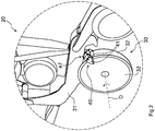
- Row unit 20 shown in a detailed view comprises a disc coulter 30 designed as a double disc coulter, two on one Has coulter holder 31 rotatably mounted disks 32.
- the disc coulter 30 each comprises a scraper assembly 40 assigned to the discs 32, which is set up to at least partially detach residues adhering to the disc 32 from the agricultural area, in particular a field, from the disc 32.
- the wiper assembly 40 is formed here from two individual wiper elements 41 designed as bending sheet metal parts, each side of the disk 32 being assigned a wiper element 41.
- the wiper elements 41 extend here essentially so far from the outer radius in the direction of an axis of rotation D of the disk 32, so that in particular the area of the disk 32 engaging the ground is in contact with the wiper elements 41 and can thus be freed from adhesions.
- a wiper element 41 designed as a bent sheet metal part is exemplary and not restricted to this embodiment.
- the at least one wiper element 41 can be designed at least partially as a, preferably metallic, formed part, in particular as a forged and / or stamped part, and / or as a plastic part.
- the wiper assembly 40 is substantially U-shaped and thereby compressible about the disk 32.
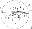
- a tensioning device 42 which is formed from at least one screw 43, a screw nut 44 and a spring element 45, is arranged transversely to the washer 32 within the wiper assembly 40 and is designed to at least partially deform the wiper elements 41 elastically and with an adjustable pressure against the washer 32 to press.
- the pressure can be adjusted particularly easily by an operator, preferably by means of a tool, by means of the screw 43 and / or the screw nut 44, a particularly high pressure between the wiper elements 41 and the disk 32 being achievable by means of the tool.
- the tensioning device 42 is also set up to apply the pressure that can be set by the wiper elements 41 to the respective sides of the disc 32 to be adjusted automatically. A particularly high operational reliability of the disc coulter 30 is thus achieved during the cultivation of the agricultural area.
- the spring element 45 can also be designed as a leaf and / or plate spring element with preferably particularly high spring rates.
- a spring element 45 designed as an elastic plastic spring element, in particular as a rubber spring, with vibration-damping properties is conceivable.
- the wiper elements 41 in each case of a wiper assembly 40 are designed in such a way that they can be detachably plugged into one another. At least one of the wiper elements 41 here has at least one at least partially bent end section 51 which can be inserted into an opening 52 provided for this purpose on the other wiper element 41. It is thus achieved that the wiper assembly 40 can be coupled to the coulter holder 31 only by one of the wiper elements 41 that can be plugged into one another by means of a tab 46 which is formed on one of the wiper elements 41.
- the positive and / or non-positive connection between the scraper assembly 40 and the share holder 31 is designed in this example as a releasable screw connection 47, with an elastic element 48 designed as an elastomer being arranged between the share holder 31 and the tab 46.
- an elastic element 48 designed as an elastomer being arranged between the share holder 31 and the tab 46.
- the wiper element 41 having the tab 46 comprises an angled end piece 49 which is bent in a direction facing away from the longitudinal axis of the wiper element 41 and at least partially rests on the coulter holder 31. Due to the additional force-transmitting connection achieved by means of the angled end piece 49 between the stripper element 41 and the coulter holder 31, in particular an in The force acting in the direction of travel and / or vertically upwards to the scraper elements 41 can be at least partially transmitted into the coulter holder 31.
- an angled end piece 49 made by bending over has an increase in rigidity and / or strength of the wiper element 41 while the weight remains at least almost the same.
- the wiper elements 41 comprise at least one end region 50 which is at least partially in contact with the disk 32 and which is also made of an almost wear-resistant material.
- a wear-resistant coating and / or a wear protection element is also conceivable. These are advantageously set up to at least partially protect the at least one end region 50 of at least one wiper element 41 from wear and / or corrosion.
- a wear-resistant material is to be understood as an at least almost abrasion-resistant and / or impact-resistant hard material, in particular hard metal. With this measure, in particular the service life of the wiper elements 41 can be increased significantly.
Landscapes
- Life Sciences & Earth Sciences (AREA)
- Soil Sciences (AREA)
- Environmental Sciences (AREA)
- Engineering & Computer Science (AREA)
- Mechanical Engineering (AREA)
- Soil Working Implements (AREA)
Applications Claiming Priority (1)
| Application Number | Priority Date | Filing Date | Title |
|---|---|---|---|
| DE102019133770.4A DE102019133770A1 (de) | 2019-12-10 | 2019-12-10 | Scheibenschar |
Publications (3)
| Publication Number | Publication Date |
|---|---|
| EP3834595A1 true EP3834595A1 (fr) | 2021-06-16 |
| EP3834595C0 EP3834595C0 (fr) | 2025-05-07 |
| EP3834595B1 EP3834595B1 (fr) | 2025-05-07 |
Family
ID=74105797
Family Applications (1)
| Application Number | Title | Priority Date | Filing Date |
|---|---|---|---|
| EP20401063.1A Active EP3834595B1 (fr) | 2019-12-10 | 2020-12-03 | Disque de charrue |
Country Status (3)
| Country | Link |
|---|---|
| EP (1) | EP3834595B1 (fr) |
| DE (1) | DE102019133770A1 (fr) |
| PL (1) | PL3834595T3 (fr) |
Citations (4)
| Publication number | Priority date | Publication date | Assignee | Title |
|---|---|---|---|---|
| US785865A (en) * | 1904-09-06 | 1905-03-28 | Spencer E Davis | Scraper for disk drills. |
| US808021A (en) * | 1905-09-02 | 1905-12-19 | Spencer E Davis | Scraper for disk drills. |
| EP0170140A1 (fr) * | 1984-07-19 | 1986-02-05 | Deere & Company | Grattoir pour disque de semoir |
| DE19653014A1 (de) | 1996-12-19 | 1998-06-25 | Amazonen Werke Dreyer H | Scheibensäschar |
Family Cites Families (2)
| Publication number | Priority date | Publication date | Assignee | Title |
|---|---|---|---|---|
| US4736803A (en) * | 1986-09-16 | 1988-04-12 | J. I. Case Company | Self-adjusting scrapers for double disk openers |
| CA2298395A1 (fr) * | 2000-02-14 | 2001-08-14 | Bourgault Industries Ltd. | Coutre a pression comportant differentes lames a reglage rapide |
-
2019
- 2019-12-10 DE DE102019133770.4A patent/DE102019133770A1/de active Pending
-
2020
- 2020-12-03 PL PL20401063.1T patent/PL3834595T3/pl unknown
- 2020-12-03 EP EP20401063.1A patent/EP3834595B1/fr active Active
Patent Citations (4)
| Publication number | Priority date | Publication date | Assignee | Title |
|---|---|---|---|---|
| US785865A (en) * | 1904-09-06 | 1905-03-28 | Spencer E Davis | Scraper for disk drills. |
| US808021A (en) * | 1905-09-02 | 1905-12-19 | Spencer E Davis | Scraper for disk drills. |
| EP0170140A1 (fr) * | 1984-07-19 | 1986-02-05 | Deere & Company | Grattoir pour disque de semoir |
| DE19653014A1 (de) | 1996-12-19 | 1998-06-25 | Amazonen Werke Dreyer H | Scheibensäschar |
Also Published As
| Publication number | Publication date |
|---|---|
| PL3834595T3 (pl) | 2025-06-16 |
| EP3834595C0 (fr) | 2025-05-07 |
| DE102019133770A1 (de) | 2021-06-10 |
| EP3834595B1 (fr) | 2025-05-07 |
Similar Documents
| Publication | Publication Date | Title |
|---|---|---|
| DE2318497C3 (de) | Reinigungsvorrichtung für ein Förderband | |
| EP1880590B1 (fr) | Dispositif d'une machine agricole | |
| EP1434654A2 (fr) | Dent de fraisage et support de dent de fraisage pour broyeuse | |
| EP1541003B1 (fr) | Protecteur contre la surcharge pour outil de travail du sol | |
| EP0056988B1 (fr) | Dispositif pour le nettoyage des faces internes des disques d'un outil constitué par deux disques tournants, plus particulièrement pour des semoirs | |
| DE202004007112U1 (de) | Aufhängungsvorrichtung einer Landmaschine | |
| DE69808706T2 (de) | Abstreifer für ein Förderband und Montageanordnung für das Abstreiferblatt | |
| EP2807910B1 (fr) | Porte-outil avec liaison soudée | |
| EP2374343B1 (fr) | Agrégat de semoir monograine | |
| EP3834595B1 (fr) | Disque de charrue | |
| EP3874930A1 (fr) | Rouleau de pression pour un appareil de travail agricole | |
| EP3760019B1 (fr) | Socs pour un appareil de traitement du sol | |
| DE202010005461U1 (de) | Blattfederelement für Bodenbearbeitungsmaschinen | |
| DE202020100913U1 (de) | Fixkammhalter für eine Kämmmaschine | |
| DE102016112634B4 (de) | Landwirtschaftliche Sämaschine mit Abstreifelement | |
| EP3771317B1 (fr) | Porte-outil pour une machine de travail du sol | |
| AT525059B1 (de) | Striegel mit gefederten Zinken für die Landwirtschaft | |
| DE102009058412A1 (de) | Bodenbearbeitungsgerätleitblech | |
| EP2732685B1 (fr) | Soc à double disque d'une machine agricole, notamment un semoir | |
| EP3704922A1 (fr) | Agencement des socs et machine de distribution dotée d'un agencement des socs | |
| DE102024122960A1 (de) | Landwirtschaftliches Arbeitsgerät | |
| EP3808161A1 (fr) | Dent de raclage pour un appareil de traitement du sol | |
| DE20201084U1 (de) | Verstellbarer Abstreifer für Scheibenschare | |
| AT235062B (de) | Zinken, insbesondere für Kultivatoren | |
| EP2589281A1 (fr) | Corps de charrue avec un versoir de charrue |
Legal Events
| Date | Code | Title | Description |
|---|---|---|---|
| PUAI | Public reference made under article 153(3) epc to a published international application that has entered the european phase |
Free format text: ORIGINAL CODE: 0009012 |
|
| STAA | Information on the status of an ep patent application or granted ep patent |
Free format text: STATUS: THE APPLICATION HAS BEEN PUBLISHED |
|
| AK | Designated contracting states |
Kind code of ref document: A1 Designated state(s): AL AT BE BG CH CY CZ DE DK EE ES FI FR GB GR HR HU IE IS IT LI LT LU LV MC MK MT NL NO PL PT RO RS SE SI SK SM TR |
|
| STAA | Information on the status of an ep patent application or granted ep patent |
Free format text: STATUS: REQUEST FOR EXAMINATION WAS MADE |
|
| 17P | Request for examination filed |
Effective date: 20211129 |
|
| RBV | Designated contracting states (corrected) |
Designated state(s): AL AT BE BG CH CY CZ DE DK EE ES FI FR GB GR HR HU IE IS IT LI LT LU LV MC MK MT NL NO PL PT RO RS SE SI SK SM TR |
|
| P01 | Opt-out of the competence of the unified patent court (upc) registered |
Effective date: 20230523 |
|
| GRAP | Despatch of communication of intention to grant a patent |
Free format text: ORIGINAL CODE: EPIDOSNIGR1 |
|
| STAA | Information on the status of an ep patent application or granted ep patent |
Free format text: STATUS: GRANT OF PATENT IS INTENDED |
|
| RIC1 | Information provided on ipc code assigned before grant |
Ipc: A01B 23/06 20060101ALI20241223BHEP Ipc: A01C 5/06 20060101AFI20241223BHEP |
|
| INTG | Intention to grant announced |
Effective date: 20250123 |
|
| GRAS | Grant fee paid |
Free format text: ORIGINAL CODE: EPIDOSNIGR3 |
|
| GRAA | (expected) grant |
Free format text: ORIGINAL CODE: 0009210 |
|
| STAA | Information on the status of an ep patent application or granted ep patent |
Free format text: STATUS: THE PATENT HAS BEEN GRANTED |
|
| AK | Designated contracting states |
Kind code of ref document: B1 Designated state(s): AL AT BE BG CH CY CZ DE DK EE ES FI FR GB GR HR HU IE IS IT LI LT LU LV MC MK MT NL NO PL PT RO RS SE SI SK SM TR |
|
| REG | Reference to a national code |
Ref country code: GB Ref legal event code: FG4D Free format text: NOT ENGLISH |
|
| REG | Reference to a national code |
Ref country code: CH Ref legal event code: EP |
|
| REG | Reference to a national code |
Ref country code: DE Ref legal event code: R096 Ref document number: 502020010998 Country of ref document: DE |
|
| REG | Reference to a national code |
Ref country code: IE Ref legal event code: FG4D Free format text: LANGUAGE OF EP DOCUMENT: GERMAN |
|
| U01 | Request for unitary effect filed |
Effective date: 20250528 |
|
| P04 | Withdrawal of opt-out of the competence of the unified patent court (upc) registered |
Free format text: CASE NUMBER: APP_26402/2025 Effective date: 20250603 |
|
| U07 | Unitary effect registered |
Designated state(s): AT BE BG DE DK EE FI FR IT LT LU LV MT NL PT RO SE SI Effective date: 20250606 |
|
| PG25 | Lapsed in a contracting state [announced via postgrant information from national office to epo] |
Ref country code: ES Free format text: LAPSE BECAUSE OF FAILURE TO SUBMIT A TRANSLATION OF THE DESCRIPTION OR TO PAY THE FEE WITHIN THE PRESCRIBED TIME-LIMIT Effective date: 20250507 |
|
| PG25 | Lapsed in a contracting state [announced via postgrant information from national office to epo] |
Ref country code: NO Free format text: LAPSE BECAUSE OF FAILURE TO SUBMIT A TRANSLATION OF THE DESCRIPTION OR TO PAY THE FEE WITHIN THE PRESCRIBED TIME-LIMIT Effective date: 20250807 Ref country code: GR Free format text: LAPSE BECAUSE OF FAILURE TO SUBMIT A TRANSLATION OF THE DESCRIPTION OR TO PAY THE FEE WITHIN THE PRESCRIBED TIME-LIMIT Effective date: 20250808 |
|
| PG25 | Lapsed in a contracting state [announced via postgrant information from national office to epo] |
Ref country code: HR Free format text: LAPSE BECAUSE OF FAILURE TO SUBMIT A TRANSLATION OF THE DESCRIPTION OR TO PAY THE FEE WITHIN THE PRESCRIBED TIME-LIMIT Effective date: 20250507 |
|
| PG25 | Lapsed in a contracting state [announced via postgrant information from national office to epo] |
Ref country code: RS Free format text: LAPSE BECAUSE OF FAILURE TO SUBMIT A TRANSLATION OF THE DESCRIPTION OR TO PAY THE FEE WITHIN THE PRESCRIBED TIME-LIMIT Effective date: 20250807 |
|
| PG25 | Lapsed in a contracting state [announced via postgrant information from national office to epo] |
Ref country code: IS Free format text: LAPSE BECAUSE OF FAILURE TO SUBMIT A TRANSLATION OF THE DESCRIPTION OR TO PAY THE FEE WITHIN THE PRESCRIBED TIME-LIMIT Effective date: 20250907 |
|
| U20 | Renewal fee for the european patent with unitary effect paid |
Year of fee payment: 6 Effective date: 20251110 |
|
| PG25 | Lapsed in a contracting state [announced via postgrant information from national office to epo] |
Ref country code: SM Free format text: LAPSE BECAUSE OF FAILURE TO SUBMIT A TRANSLATION OF THE DESCRIPTION OR TO PAY THE FEE WITHIN THE PRESCRIBED TIME-LIMIT Effective date: 20250507 |
|
| PG25 | Lapsed in a contracting state [announced via postgrant information from national office to epo] |
Ref country code: CZ Free format text: LAPSE BECAUSE OF FAILURE TO SUBMIT A TRANSLATION OF THE DESCRIPTION OR TO PAY THE FEE WITHIN THE PRESCRIBED TIME-LIMIT Effective date: 20250507 |
|
| PGFP | Annual fee paid to national office [announced via postgrant information from national office to epo] |
Ref country code: PL Payment date: 20250912 Year of fee payment: 6 |
|
| PG25 | Lapsed in a contracting state [announced via postgrant information from national office to epo] |
Ref country code: SK Free format text: LAPSE BECAUSE OF FAILURE TO SUBMIT A TRANSLATION OF THE DESCRIPTION OR TO PAY THE FEE WITHIN THE PRESCRIBED TIME-LIMIT Effective date: 20250507 |
|
| PLBE | No opposition filed within time limit |
Free format text: ORIGINAL CODE: 0009261 |
|
| STAA | Information on the status of an ep patent application or granted ep patent |
Free format text: STATUS: NO OPPOSITION FILED WITHIN TIME LIMIT |
|
| REG | Reference to a national code |
Ref country code: CH Ref legal event code: L10 Free format text: ST27 STATUS EVENT CODE: U-0-0-L10-L00 (AS PROVIDED BY THE NATIONAL OFFICE) Effective date: 20260318 |
|
| 26N | No opposition filed |
Effective date: 20260210 |