EP3834902A1 - Installation de traitement de boue organique et procédé de traitement - Google Patents
Installation de traitement de boue organique et procédé de traitement Download PDFInfo
- Publication number
- EP3834902A1 EP3834902A1 EP20748637.4A EP20748637A EP3834902A1 EP 3834902 A1 EP3834902 A1 EP 3834902A1 EP 20748637 A EP20748637 A EP 20748637A EP 3834902 A1 EP3834902 A1 EP 3834902A1
- Authority
- EP
- European Patent Office
- Prior art keywords
- organic sludge
- dewatering
- thickening
- hot water
- filtration screen
- Prior art date
- Legal status (The legal status is an assumption and is not a legal conclusion. Google has not performed a legal analysis and makes no representation as to the accuracy of the status listed.)
- Pending
Links
Images


Classifications
-
- B—PERFORMING OPERATIONS; TRANSPORTING
- B01—PHYSICAL OR CHEMICAL PROCESSES OR APPARATUS IN GENERAL
- B01D—SEPARATION
- B01D29/00—Filters with filtering elements stationary during filtration, e.g. pressure or suction filters, not covered by groups B01D24/00 - B01D27/00; Filtering elements therefor
- B01D29/50—Filters with filtering elements stationary during filtration, e.g. pressure or suction filters, not covered by groups B01D24/00 - B01D27/00; Filtering elements therefor with multiple filtering elements, characterised by their mutual disposition
- B01D29/52—Filters with filtering elements stationary during filtration, e.g. pressure or suction filters, not covered by groups B01D24/00 - B01D27/00; Filtering elements therefor with multiple filtering elements, characterised by their mutual disposition in parallel connection
- B01D29/54—Filters with filtering elements stationary during filtration, e.g. pressure or suction filters, not covered by groups B01D24/00 - B01D27/00; Filtering elements therefor with multiple filtering elements, characterised by their mutual disposition in parallel connection arranged concentrically or coaxially
-
- B—PERFORMING OPERATIONS; TRANSPORTING
- B01—PHYSICAL OR CHEMICAL PROCESSES OR APPARATUS IN GENERAL
- B01D—SEPARATION
- B01D29/00—Filters with filtering elements stationary during filtration, e.g. pressure or suction filters, not covered by groups B01D24/00 - B01D27/00; Filtering elements therefor
- B01D29/11—Filters with filtering elements stationary during filtration, e.g. pressure or suction filters, not covered by groups B01D24/00 - B01D27/00; Filtering elements therefor with bag, cage, hose, tube, sleeve or like filtering elements
- B01D29/114—Filters with filtering elements stationary during filtration, e.g. pressure or suction filters, not covered by groups B01D24/00 - B01D27/00; Filtering elements therefor with bag, cage, hose, tube, sleeve or like filtering elements arranged for inward flow filtration
-
- B—PERFORMING OPERATIONS; TRANSPORTING
- B01—PHYSICAL OR CHEMICAL PROCESSES OR APPARATUS IN GENERAL
- B01D—SEPARATION
- B01D29/00—Filters with filtering elements stationary during filtration, e.g. pressure or suction filters, not covered by groups B01D24/00 - B01D27/00; Filtering elements therefor
- B01D29/11—Filters with filtering elements stationary during filtration, e.g. pressure or suction filters, not covered by groups B01D24/00 - B01D27/00; Filtering elements therefor with bag, cage, hose, tube, sleeve or like filtering elements
- B01D29/117—Filters with filtering elements stationary during filtration, e.g. pressure or suction filters, not covered by groups B01D24/00 - B01D27/00; Filtering elements therefor with bag, cage, hose, tube, sleeve or like filtering elements arranged for outward flow filtration
-
- B—PERFORMING OPERATIONS; TRANSPORTING
- B01—PHYSICAL OR CHEMICAL PROCESSES OR APPARATUS IN GENERAL
- B01D—SEPARATION
- B01D29/00—Filters with filtering elements stationary during filtration, e.g. pressure or suction filters, not covered by groups B01D24/00 - B01D27/00; Filtering elements therefor
- B01D29/62—Regenerating the filter material in the filter
- B01D29/64—Regenerating the filter material in the filter by scrapers, brushes, nozzles, or the like, acting on the cake side of the filtering element
- B01D29/6469—Regenerating the filter material in the filter by scrapers, brushes, nozzles, or the like, acting on the cake side of the filtering element scrapers
- B01D29/6476—Regenerating the filter material in the filter by scrapers, brushes, nozzles, or the like, acting on the cake side of the filtering element scrapers with a rotary movement with respect to the filtering element
-
- C—CHEMISTRY; METALLURGY
- C02—TREATMENT OF WATER, WASTE WATER, SEWAGE, OR SLUDGE
- C02F—TREATMENT OF WATER, WASTE WATER, SEWAGE, OR SLUDGE
- C02F11/00—Treatment of sludge; Devices therefor
- C02F11/12—Treatment of sludge; Devices therefor by de-watering, drying or thickening
- C02F11/121—Treatment of sludge; Devices therefor by de-watering, drying or thickening by mechanical de-watering
- C02F11/125—Treatment of sludge; Devices therefor by de-watering, drying or thickening by mechanical de-watering using screw filters
-
- C—CHEMISTRY; METALLURGY
- C02—TREATMENT OF WATER, WASTE WATER, SEWAGE, OR SLUDGE
- C02F—TREATMENT OF WATER, WASTE WATER, SEWAGE, OR SLUDGE
- C02F11/00—Treatment of sludge; Devices therefor
- C02F11/18—Treatment of sludge; Devices therefor by thermal conditioning
-
- C—CHEMISTRY; METALLURGY
- C02—TREATMENT OF WATER, WASTE WATER, SEWAGE, OR SLUDGE
- C02F—TREATMENT OF WATER, WASTE WATER, SEWAGE, OR SLUDGE
- C02F11/00—Treatment of sludge; Devices therefor
- C02F11/12—Treatment of sludge; Devices therefor by de-watering, drying or thickening
- C02F11/14—Treatment of sludge; Devices therefor by de-watering, drying or thickening with addition of chemical agents
-
- C—CHEMISTRY; METALLURGY
- C02—TREATMENT OF WATER, WASTE WATER, SEWAGE, OR SLUDGE
- C02F—TREATMENT OF WATER, WASTE WATER, SEWAGE, OR SLUDGE
- C02F2209/00—Controlling or monitoring parameters in water treatment
- C02F2209/09—Viscosity
Definitions
- the present invention relates to an organic sludge treatment facility including dewatering means for dewatering organic sludge such as sewage sludge generated from, for example, a sewage treatment plant, and an organic sludge treatment method in which such organic sludge is dewatered by the dewatering means.
- Patent Document 1 describes a dewatering device including an outer cylinder screen having a small hole formed on a circumferential wall, a screw shaft provided inside the outer cylinder screen, and a screw blade provided in a spiral shape around the screw shaft. By rotating the screw blade and the screw shaft, a dewatering object put into the outer cylinder screen is compressed while being transported in an axial direction of the screw shaft. Moisture separated from the dewatering object is discharged from the small hole of the outer cylinder screen.
- the outer cylinder screen has a heating surface to be heated and a filtration surface where the small hole is exposed.
- a heating jacket having a configuration for circulating a heat medium inside is attached to a part of the outer cylinder screen.
- the portion of the outer cylinder screen, to which the heating jacket is attached, is used as the heating surface, and the heating surface and the filtration surface are alternately and repeatedly disposed in the axial direction of the screw shaft.
- the moisture content of the dewatered sludge is reduced by dewatering the dewatering object transported in the outer cylinder screen while heating the dewatering object by the heating surface of the outer cylinder screen.
- Patent Document 1 PCT International Publication No. WO2017/043232
- the portion of the outer cylinder screen, to which the heating jacket is attached is the heating surface and the small hole separated from the dewatering object such as the filtration surface is not formed on the heating surface. Therefore, if the area of the heating surface is increased in order to further reduce the moisture content of the dewatered sludge, the area of the filtration surface is decreased and moisture separated from the dewatering object cannot be efficiently discharged. On the contrary, if the area of the filtration surface on which the small hole is formed is increased, the area of the heating surface is reduced and the moisture content of the dewatered sludge cannot be reduced.
- the present invention is made under such a background, and an object of the present invention is to provide an organic sludge treatment facility including dewatering means capable of achieving both a low moisture content and efficient discharge of moisture separated from the organic sludge by heating the organic sludge, and a treatment method.
- An organic sludge treatment facility of the present invention is an organic sludge treatment facility including: dewatering means for dewatering organic sludge.
- dewatering means for dewatering organic sludge.
- a filtration screen that filters the organic sludge is disposed in a casing.
- the organic sludge is supplied to a first space, and dewatering hot water at a temperature of 50°C or higher and lower than 100°C is supplied from dewatering hot water supply means to a second space among a plurality of spaces in the casing separated by the filtration screen.
- an organic sludge treatment method of the present invention is an organic sludge treatment method for dewatering organic sludge by dewatering means, the method including: disposing a filtration screen that filters the organic sludge in a casing in the dewatering means; and supplying the organic sludge to a first space, and supplying dewatering hot water at a temperature in a range of 50°C or higher and lower than 100°C from dewatering hot water supply means to a second space among a plurality of spaces in the casing separated by the filtration screen.
- the organic sludge in the dewatering means, the organic sludge is supplied to the first space, and the dewatering hot water at the temperature in the range of 50°C or higher and lower than 100°C is supplied from the dewatering hot water supply means to the second space among the plurality of spaces in the casing separated by the filtration screen that filters the organic sludge. Therefore, the organic sludge supplied to the first space is heated by the dewatering hot water supplied to the second space, such that the viscosity of the organic sludge is lowered, and the moisture retained in the organic sludge is separated by thermal denaturation of protein.
- the moisture content of the organic sludge can be reduced. Further, since the filtration resistance is decreased by lowering the viscosity of the organic sludge, the discharge of the moisture separated from the organic sludge can be facilitated. Therefore, according to the organic sludge treatment facility and the treatment method having the configuration described above, the moisture content of the dewatered organic sludge can be reduced and the moisture separated from the organic sludge can be efficiently discharged.
- the temperature of the dewatering hot water is lower than 50°C, the effects of lowering the viscosity of the organic sludge and separating the moisture described above cannot be sufficiently obtained. Further, when the temperature of the dewatering hot water exceeds 100°C, it becomes difficult to handle. It is desirable that the temperature of the dewatering hot water is in a range of 60°C or higher and 90°C or lower. The higher the temperature of the dewatering hot water, the more the viscosity of the organic sludge decreases and the separation of the moisture due to the thermal denaturation of the protein is promoted. In a case where hot water used in the treatment facility is used as the dewatering hot water, a temperature in a range of 60°C or higher and 90°C or lower is realistic.
- the dewatering means includes an inner filtration screen disposed in the casing and having a cylindrical or conical shape centered on an axis extending in a vertical direction, an outer filtration screen disposed in the casing on an outside of the inner filtration screen with a gap and having a cylindrical or conical shape coaxial with the inner filtration screen, and a ribbon screw that is accommodated between the inner filtration screen and the outer filtration screen in a spiral shape twisting around the axis and is rotated relative to the inner filtration screen and the outer filtration screen centered on the axis, and a space between the inner filtration screen and the outer filtration screen is defined as the first space, and a space inside the inner filtration screen and a space outside the outer filtration screen are defined as the second space.
- the organic sludge treatment facility may further include thickening means for thickening the organic sludge that is coagulated by adding a coagulant in a preceding stage of the dewatering means, and the organic sludge thickened by the thickening means may be dewatered by the dewatering means.
- the thickening hot water supply means also supplies the thickening hot water having a temperature of 50°C or higher and lower than 100°C to the thickening means and the thickening hot water is mixed with the organic sludge. Therefore, the protein can be thermally denatured by heating the organic sludge also in the thickening means, the retained moisture can be separated, and the dewatering efficiency in the dewatering means of the subsequent stage can be further improved.
- the temperature of the thickening hot water is in the range of 60°C or higher and 90°C or lower for the same reason as the dewatering hot water supplied to the dewatering means.
- the organic sludge is thickened to a sludge concentration of 5 wt% or higher by the thickening means, and it is more desirable that the organic sludge is thickened to a sludge concentration in a range of 8 wt% to 10 wt%.
- a coagulant is added to the organic sludge thickened by the thickening means.
- the dewatering hot water discharged from the dewatering means is circulated and supplied to the thickening means as the thickening hot water supplied to the thickening means.
- both a low moisture content of the dewatered organic sludge and efficient discharge of moisture separated from the organic sludge by heating the organic sludge can be achieved.
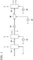
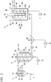
- Figs. 1 and 2 show a first embodiment of an organic sludge treatment facility of the present invention, and an organic sludge treatment method of the present invention is also described while describing below the first embodiment of the organic sludge treatment facility.
- the organic sludge treatment facility of the present embodiment includes coagulation means 1 for coagulating organic sludge A such as sewage sludge of mixed raw sludge generated and supplied, for example, from a sewage treatment plant by adding a polymer coagulant B to the organic sludge A, thickening means 2 for thickening coagulated sludge C of which a solid content is coagulated to some extent by the coagulation means 1, dewatering means 3 for dewatering thickened sludge D thickened by the thickening means 2, and a thickened sludge supply path 4 which connects the thickening means 2 and the dewatering means 3.
- coagulation means 1 for coagulating organic sludge A such as sewage sludge of mixed
- the coagulation means 1 includes a bottomed cylindrical coagulation tank 1A having a central axis extending in a vertical direction, in which the organic sludge A and the polymer coagulant B are supplied from the bottom to be held.
- the coagulation tank 1A is provided with stirring means 1B in which a stirring blade 1b is attached to a rotation shaft 1a along the central axis of the coagulation tank 1A, and which stirs and mixes the organic sludge A and the polymer coagulant B by rotating the rotation shaft 1a and the stirring blade 1b by rotation drive means 1c such as a motor provided on an upper portion of the coagulation tank 1A.
- the coagulated sludge C which is stirred and mixed with the polymer coagulant B by the stirring means 1B to be coagulated, is extracted from the upper portion of the coagulation tank 1A and supplied to the thickening means 2.
- the thickening means 2 is a vertical type filtration thickening device, and includes a bottomed cylindrical thickening tank 2A having a central axis extending in the vertical direction similar to the coagulation tank 1A, in which the coagulated sludge C supplied from the coagulation means 1 is held.
- the coagulated sludge C is supplied from the upper portion of the thickening tank 2A into the thickening tank 2A.
- the body of the thickening tank 2A is a thickening filtration screen 2a formed of wedge wire, punching metal, or the like, and an outer circumference of the thickening filtration screen 2a is a jacket-like liquid filtration chamber 2b.
- a screw 2d is attached to a rotation shaft 2c extending along the central axis of the thickening tank 2A, and transporting means 2B is provided for transporting the coagulated sludge C by rotating the rotation shaft 2c and the screw 2d by rotation drive means 2e such as a motor provided on the upper portion of the thickening tank 2A.
- the coagulated sludge C supplied from the upper portion of the thickening tank 2A is transported downward by the transporting means 2B, and moisture is separated and thickened by the thickening filtration screen 2a, and the coagulated sludge C is thickened at a sludge concentration of 5 wt% or higher, preferably to a sludge concentration in a range of 8 wt% to 10 wt%, extracted from the bottom of the thickening tank 2A, and supplied to the thickened sludge supply path 4 as thickened sludge D.
- the bottoms of the thickening tank 2A and the coagulation tank 1A are each formed in a truncated cone shape of which a diameter decreases downward. Further, the moisture separated from the coagulated sludge C by the thickening filtration screen 2a is accommodated in the liquid filtration chamber 2b and treated as wastewater E.
- thickening hot water F having a temperature in a range of 50°C or higher and lower than 100°C, preferably a temperature in a range of 60°C or higher and 90°C or lower is supplied by a pump 2C to the thickening means 2, and is mixed with the coagulated sludge C supplied from the coagulation means 1.
- the rotation shaft 2c of the transporting means 2B of the thickening means 2 has a hollow cylindrical shape, and a large (plurality) number of through-holes are formed in the cylindrical wall portion of the rotation shaft 2c. Then, the thickening hot water F is supplied from a lower end of the rotation shaft 2c into the rotation shaft 2c, ejected from the through-holes, and is supplied to the coagulated sludge C, which is supplied from the coagulation means 1 into the thickening tank 2A and held therein, to be mixed.
- the coagulated sludge C is heated in the thickening means 2, the protein is thermally denatured, the retained moisture is separated and discharged as the wastewater E together with the thickening hot water F, and the thickened sludge D is thickened to the concentration as described above.
- the thickened sludge supply path 4 to which the thickened sludge D thus thickened is supplied is provided with a pump 4A that sends the thickened sludge D to the dewatering means 3, and mixing means 4B such as a high-speed mixer is provided between the pump 4A and the dewatering means 3.
- An inorganic coagulant such as poly-ferric sulfate (PFS) or a coagulant G such as the polymer coagulant is supplied by the pump 4C to the mixing means 4B, and added to the thickened sludge D to be mixed.
- a filtration screen 3B for filtering the thickened sludge D is disposed in a casing 3A, and the thickened sludge D is supplied to a first space 3A1 among a plurality of spaces in the casing 3A separated by the filtration screen 3B.
- the dewatering means 3 is a vertical type screw press and includes an inner filtration screen 3a as the second filtration screen 3B, which is disposed in the casing 3A and has a cylindrical or conical shape centered on an axis extending in the vertical direction coaxial with the casing 3A, an outer filtration screen 3b which has a cylindrical or conical shape coaxial with the inner filtration screen 3a on the outside of the inner filtration screen 3a with a gap, and is disposed in the casing 3A, and a ribbon screw 3d which is accommodated between the inner filtration screen 3a and the outer filtration screen 3b in a spiral shape twisting around the axis, and is rotated relative to the inner filtration screen 3a and the outer filtration screen 3b centered on the axis by rotation drive means 3c such as a motor.
- rotation drive means 3c such as a motor.
- a space between the inner filtration screen 3a and the outer filtration screen 3b is set as a first space 3A1 to which the thickened sludge D is supplied, and a space inside the inner filtration screen 3a and a space inside the casing 3A and outside the outer filtration screen 3b are set as a second space 3A2.
- Dewatering hot water H having a temperature in a range of 50°C or higher and lower than 100°C, preferably a temperature in a range of 60°C or higher and 90°C or lower is supplied by a pump 3P from dewatering hot water supply means (not shown) to the second space 3A2.
- the inner filtration screen 3a and the outer filtration screen 3b are also formed of wedge wire, punching metal, or the like.
- the casing 3A has a bottomed cylindrical shape centered on the axis, and the thickened sludge D is supplied from the bottom of the casing 3A to the first space 3A1 via a supply pipe 3f connected to an annular plate-shaped connecting plate 3e that connects the bottoms of the inner filtration screen 3a and the outer filtration screen 3b.
- the moisture is separated by the inner filtration screen 3a and the outer filtration screen 3b while the thickened sludge D is transported upward by the relative rotation of the ribbon screw 3d.
- annular plate-shaped board 3C is disposed on the upper portion in the casing 3A, and the outer filtration screen 3b is attached to an inner circumferential portion of the board 3C to be fixed.
- a lid 3D is disposed in an upper opening of the casing 3A above the board 3C, the inner filtration screen 3a is attached to the lid 3D to be fixed, and the rotation drive means 3c is disposed on the lid 3D and rotates the ribbon screw 3d via a cylindrical screw support that covers the upper portion of the inner filtration screen 3a.
- the inner filtration screen 3a and the outer filtration screen 3b are fixed to the casing, and the ribbon screw 3d is rotated by the rotation drive means 3c, but conversely, the ribbon screw 3d is fixed, and the inner filtration screen 3a and the outer filtration screen 3b may be rotated, or both of the ribbon screw 3d and the combination of the inner filtration screen 3a and the outer filtration screen 3b may be rotated in opposite directions to each other.
- an upper space in the casing 3A between the board 3C and the lid 3D is a discharge chamber 3E, and an annular upper opening of the first space 3A1 in the discharge chamber 3E is a discharge port 3F.
- the discharge port 3F is provided with a squeezing ring 3G having a truncated cone-shaped outer circumferential surface centered on the axis, which goes upward toward an outer circumferential side.
- Dewatered sludge I dewatered from the thickened sludge D in which moisture is separated while the thickened sludge D is transported upward in the first space 3A1 by the ribbon screw 3d, flows out from the discharge port 3F to the discharge chamber 3E while being squeezed by the squeezing ring 3G to be discharged.
- dewatering hot water H is also supplied from the bottom of the casing 3A to the second space 3A2 in the casing 3A.
- the dewatering hot water H supplied to the second space 3A2 heats the thickened sludge D in the first space 3A1. Therefore, the protein of the thickened sludge D is thermally denatured, and thereby the retained moisture is separated and filtered by the inner filtration screen 3a and the outer filtration screen 3b.
- the moisture is discharged as wastewater J from a wastewater pipe 3H raised from the second space 3A2 together with the dewatering hot water H that is cooled by heating the thickened sludge D.
- the thickened sludge D is supplied to the first space 3A1, and the dewatering hot water H having a temperature in a range of 50°C or higher and a lower than 100°C is supplied from the dewatering hot water supply means to the second space 3A2.
- the thickened sludge D supplied to the first space 3A1 is heated by the dewatering hot water H supplied to the second space 3A2, such that the viscosity of the thickened sludge D decreases and the moisture retained in the thickened sludge D is separated by thermal denaturation of the protein.
- the moisture separated from the thickened sludge D is filtered through the filtration screen 3B, flows into the second space 3A2, and is discharged together with the cooled dewatering hot water H. Therefore, the moisture content of the dewatered sludge I discharged from the discharge port 3F to the discharge chamber 3E can be reduced. Further, as described above, since the filtration resistance is reduced by lowering the viscosity of the thickened sludge D, the discharge of the moisture separated from the thickened sludge D into the second space 3A2 can be facilitated. Therefore, according to the organic sludge treatment facility and treatment method having the configuration described above, it is possible to achieve both a low moisture content of the dewatered sludge I and an efficient discharge of the moisture separated from the thickened sludge D.
- smoke effluent treatment tower wastewater of a sludge incineration facility installed in the organic sludge treatment facility, scrubber wastewater of a sludge drying facility, or hot water generated from a digestion gas generator can be used. Further, it is also possible to heat clean water, sand filtered water, or the like with a boiler to be used.
- the temperature of the dewatering hot water H is lower than 50°C, as described above, the effects of lowering the viscosity of the thickened sludge D and separating the moisture cannot be sufficiently obtained. Further, when the temperature of the dewatering hot water H exceeds 100°C, it becomes difficult to handle. The higher the temperature of the dewatering hot water H, the lower the viscosity of the thickened sludge D and the promotion of the moisture separation due to the thermal denaturation of the protein can be achieved. However, as described above, in a case where the hot water used in the organic sludge treatment facility is used as the dewatering hot water H, the temperature in a range of 60°C or higher and 90°C or lower is realistic.
- the dewatering means 3 is the vertical type screw press including the inner filtration screen 3a which is disposed in the casing 3A having a cylindrical or conical shape centered on the axis extending in the vertical direction, the outer filtration screen 3b which is disposed in the casing 3A on the outside of the inner filtration screen 3a with a gap and having a cylindrical or conical shape coaxial with the inner filtration screen 3a, and the ribbon screw 3d which is accommodated between the inner filtration screen 3a and the outer filtration screen 3b in a spiral shape twisting around the axis, and is rotated relative to the inner filtration screen 3a and the outer filtration screen 3b centered on the axis.
- a space between the inner filtration screen 3a and the outer filtration screen 3b as the filtration screen 3B is the first space 3A1 to which the thickened sludge D is supplied, and a space inside the inner filtration screen 3a and a space outside the outer filtration screen 3b are the second space 3A2 to which the dewatering hot water H is supplied.
- the thickened sludge D supplied to the first space 3A1 between the inner filtration screen 3a and the outer filtration screen 3b is transported in the axial direction by the relative rotation of the ribbon screw 3d, the thickened sludge D is dewatered by the inner filtration screen 3a and the outer filtration screen 3b. Therefore, a large filtration area can be ensured and more efficient filtration can be achieved. Further, since the thickened sludge D supplied to the first space 3A1 can be heated by the dewatering hot water H supplied to the inside of the first space 3A1 and the second space 3A2 outside thereof, the separation of moisture by the thermal denaturation of the protein can be promoted more efficiently.
- 80% or higher, and more preferably the entire surface of the filtration surfaces of the inner filtration screen 3a and the outer filtration screen 3b, is always in direct contact with the dewatering hot water H. Therefore, in the dewatering process of the thickened sludge D, heating of the thickened sludge D supplied to the first space 3A1 via the filtration screen can be sufficiently performed, and the separation of moisture by thermal denaturation of the protein can be promoted more efficiently. Further, since the filtration surface is always in direct contact with the dewatering hot water H, the filtration surface does not come into contact with the atmosphere. Therefore, clogging due to drying of the filtration surface can be prevented.
- the vertical type screw press including two the filtration screens 3B that is, the inner filtration screen 3a and the outer filtration screen 3b is used as the dewatering means 3, but it is also possible to use a vertical type screw press in which a screw in a spiral shape twisted around the axis, which is rotated centered on the axis, is disposed in one cylindrical or conical filtration screen centered on the axis extending in the vertical direction, or a lateral type screw press which is described in Patent Document 1. In addition to these, a rotary press or a multi-plate type screw press can also be used.
- the thickening means 2 thickening the coagulated sludge C, which is coagulated by adding the polymer coagulant B to the organic sludge A in the coagulation means 1, is provided in a preceding stage of the dewatering means 3.
- the thickened sludge D thickened by the thickening means 2 is dewatered by the dewatering means 3.
- the thickening hot water supply means also supplies the thickening hot water F having a temperature in a range of 50°C or higher and lower than 100°C to the thickening means 2 and the thickening hot water F is mixed with the coagulated sludge C. Therefore, also in the thickening means 2 in the preceding stage of the dewatering means 3, the protein can be thermally denatured by heating the coagulated sludge C, and the moisture retained in the coagulated sludge C can be separated to further improve the dewatering efficiency of the dewatering means 3 in the subsequent stage.
- the thickening hot water F by mixing the thickening hot water F with the coagulated sludge C in the thickening means 2, an coagulation inhibitor contained in the liquid of the coagulated sludge C can be replaced with the thickening hot water F. Therefore, the coagulant G such as poly-ferric sulfate added in the thickened sludge supply path 4 can be prevented from being consumed by the coagulation inhibitor, and the coagulant G can be efficiently reacted with a solid content of the thickened sludge D. Further, by heating the coagulated sludge C with the thickening hot water F, the reactivity between the coagulant G and the thickened sludge D can also be improved, and the amount of the coagulant G added can be reduced.
- the coagulant G such as poly-ferric sulfate added in the thickened sludge supply path 4 can be prevented from being consumed by the coagulation inhibitor, and the coagulant G can be efficiently reacted with a solid content
- the dewatering efficiency in the dewatering means 3 may not be reliably improved, and when it is 100°C or higher, the handleability of the thickening hot water F is impaired. Further, it is desirable that the temperature of the thickening hot water F is in a range of 60°C or higher and 90°C or lower.
- the thickening means 2 is the vertical type thickening device in which a screw 2d is attached to a rotation shaft 2c extending along the central axis of the thickening tank 2A extending in the vertical direction, and transporting means 2B is provided for transporting the coagulated sludge C by rotating the rotation shaft 2c and the screw 2d by rotation drive means 2e.
- a belt type thickening device, a drum type thickening device, or a honeycomb type thickening device can also be used as long as it is a thickening device that does not destroy the coagulated sludge C other than a centrifugal thickening device that destroys the coagulated sludge C.
- the thickening hot water F is also added to the coagulated sludge C to be mixed in the thickening means 2, but as in a second embodiment of the present invention shown in the schematic diagram in Fig. 3 , the thickening hot water F may not be supplied to the thickening means 2.
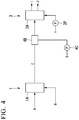
- Figs. 3 to 5 the same reference numerals are given to the portions common to those in the schematic diagram shown in Fig. 1 .
- the coagulated sludge C coagulated by the coagulation means 1 is thickened by the thickening means 2 and then supplied to the dewatering means 3.
- the coagulated sludge C may be directly supplied to the dewatering means 3 without providing the thickening means 2.
- the dewatering hot water H at 80°C must be supplied to the dewatering means 3 at 17.5m 3 /h and the wastewater (separation water) J at 60°C must be discharged at (9.2+17.5) m 3 /h. Therefore, since the supply amount of the dewatering hot water h supplied to the dewatering means 3 is about four times as large, it is desirable that the thickening means 2 is provided in the preceding stage of the dewatering means 3.
- the dewatering hot water H supplied to the dewatering means 3 is discharged as the wastewater J, but as in a fourth embodiment of the present invention shown in the schematic diagram in Fig. 5 , the dewatering hot water discharged from the dewatering means 3 may be circulated and supplied to the thickening means 2 as circulating thickening hot water K so as to be reused.
- the dewatering hot water as the circulating thickening hot water K discharged from the dewatering means 3 also includes the separation solution discharged from the dewatering means 3. Therefore, according to the fourth embodiment, the insoluble solid content (SS) in the separation solution can be captured by the thickening means 2 to improve the SS recovery rate. Further, since the residual polymer in the separation solution can be effectively used, the performance of the dewatering means 3 can be improved, and the temperature of the thickened sludge D can be further increased to further improve the dewatering efficiency.
- an organic sludge treatment facility of the present application By applying the organic sludge treatment facility of the present application to the relevant field, it is possible to provide an organic sludge treatment facility including dewatering means and a treatment method capable of achieving both a low moisture content and an efficient discharge of moisture separated from the organic sludge by heating the organic sludge.
Landscapes
- Chemical & Material Sciences (AREA)
- Engineering & Computer Science (AREA)
- Chemical Kinetics & Catalysis (AREA)
- Water Supply & Treatment (AREA)
- Hydrology & Water Resources (AREA)
- Environmental & Geological Engineering (AREA)
- Life Sciences & Earth Sciences (AREA)
- Organic Chemistry (AREA)
- Mechanical Engineering (AREA)
- Physics & Mathematics (AREA)
- Thermal Sciences (AREA)
- Treatment Of Sludge (AREA)
- Filtration Of Liquid (AREA)
Applications Claiming Priority (2)
| Application Number | Priority Date | Filing Date | Title |
|---|---|---|---|
| JP2019013443A JP6688916B1 (ja) | 2019-01-29 | 2019-01-29 | 有機性汚泥の処理設備および処理方法 |
| PCT/JP2020/002210 WO2020158551A1 (fr) | 2019-01-29 | 2020-01-23 | Installation de traitement de boue organique et procédé de traitement |
Publications (2)
| Publication Number | Publication Date |
|---|---|
| EP3834902A1 true EP3834902A1 (fr) | 2021-06-16 |
| EP3834902A4 EP3834902A4 (fr) | 2022-04-27 |
Family
ID=70413747
Family Applications (1)
| Application Number | Title | Priority Date | Filing Date |
|---|---|---|---|
| EP20748637.4A Pending EP3834902A4 (fr) | 2019-01-29 | 2020-01-23 | Installation de traitement de boue organique et procédé de traitement |
Country Status (4)
| Country | Link |
|---|---|
| EP (1) | EP3834902A4 (fr) |
| JP (1) | JP6688916B1 (fr) |
| CN (1) | CN112672804B (fr) |
| WO (1) | WO2020158551A1 (fr) |
Cited By (1)
| Publication number | Priority date | Publication date | Assignee | Title |
|---|---|---|---|---|
| EP3834904A4 (fr) * | 2019-01-29 | 2022-04-13 | Tsukishima Kikai Co., Ltd. | Installation de traitement de boue organique et procédés de traitement |
Families Citing this family (2)
| Publication number | Priority date | Publication date | Assignee | Title |
|---|---|---|---|---|
| JP7536680B2 (ja) * | 2021-02-17 | 2024-08-20 | 月島Jfeアクアソリューション株式会社 | 汚泥脱水機、汚泥処理設備、汚泥脱水方法 |
| JP7471252B2 (ja) * | 2021-03-30 | 2024-04-19 | 月島Jfeアクアソリューション株式会社 | 汚泥処理設備及び汚泥処理方法 |
Family Cites Families (11)
| Publication number | Priority date | Publication date | Assignee | Title |
|---|---|---|---|---|
| DE3009710A1 (de) * | 1979-03-15 | 1980-09-18 | Uop Inc | Verfahren zum mechanischen entwaessern von nachklaerschlamm |
| JPS6041356Y2 (ja) * | 1980-05-28 | 1985-12-16 | 荏原インフイルコ株式会社 | 泥状物脱水装置 |
| DE69304724T2 (de) * | 1992-01-31 | 1997-03-06 | Hitachi Shipbuilding Eng Co | Entwässerungsvorrichtung auf Basis einer Schraubenpresse |
| JP4097030B2 (ja) * | 2003-06-04 | 2008-06-04 | 株式会社荏原製作所 | 脱水乾燥装置及び方法 |
| US8388836B1 (en) * | 2012-09-05 | 2013-03-05 | Emerald Waste Solutions, LLC | Waste separator apparatus and system for treating animal waste and the like |
| US9782702B2 (en) * | 2014-05-22 | 2017-10-10 | Pall Corporation | Filter assemblies, filter elements, and methods for filtering liquids |
| JP6672318B2 (ja) | 2015-09-07 | 2020-03-25 | 水ing株式会社 | 脱水装置、脱水システム、及び脱水方法 |
| JP6623094B2 (ja) * | 2016-03-24 | 2019-12-18 | 月島機械株式会社 | 汚泥処理設備および汚泥処理方法 |
| JP6639330B2 (ja) * | 2016-05-30 | 2020-02-05 | 水ing株式会社 | 脱水システム及び脱水方法 |
| JP6718400B2 (ja) * | 2017-03-01 | 2020-07-08 | 水ing株式会社 | 脱水装置、脱水システム、及び脱水方法 |
| CN108947179A (zh) * | 2018-07-11 | 2018-12-07 | 国合千庭控股有限公司 | 一种污泥薄膜干燥机 |
-
2019
- 2019-01-29 JP JP2019013443A patent/JP6688916B1/ja active Active
-
2020
- 2020-01-23 WO PCT/JP2020/002210 patent/WO2020158551A1/fr not_active Ceased
- 2020-01-23 EP EP20748637.4A patent/EP3834902A4/fr active Pending
- 2020-01-23 CN CN202080004998.6A patent/CN112672804B/zh active Active
Cited By (1)
| Publication number | Priority date | Publication date | Assignee | Title |
|---|---|---|---|---|
| EP3834904A4 (fr) * | 2019-01-29 | 2022-04-13 | Tsukishima Kikai Co., Ltd. | Installation de traitement de boue organique et procédés de traitement |
Also Published As
| Publication number | Publication date |
|---|---|
| JP6688916B1 (ja) | 2020-04-28 |
| EP3834902A4 (fr) | 2022-04-27 |
| CN112672804B (zh) | 2022-11-04 |
| CN112672804A (zh) | 2021-04-16 |
| JP2020121253A (ja) | 2020-08-13 |
| WO2020158551A1 (fr) | 2020-08-06 |
Similar Documents
| Publication | Publication Date | Title |
|---|---|---|
| EP3834902A1 (fr) | Installation de traitement de boue organique et procédé de traitement | |
| EP3834904A1 (fr) | Installation de traitement de boue organique et procédés de traitement | |
| JP4953098B2 (ja) | 凝集装置を有するスクリュープレス | |
| JPH02160063A (ja) | デカンタ型遠心分離機を用いる汚泥の脱水方法および装置 | |
| CN103570214A (zh) | 移动型螺杆脱水设备 | |
| KR101057388B1 (ko) | 응집을 이용한 폐수중의 슬러지 분리장치 | |
| CN105668961B (zh) | 污泥处理装置及方法 | |
| JP2010234291A (ja) | 担体分離装置及びこれを用いた排水処理方法 | |
| KR101339718B1 (ko) | 다점 증기 분사방식의 반응장치 및 이를 구비한 유기성 폐기물 처리장치 | |
| JP2009142791A (ja) | 濃縮機構付きスクリュープレス | |
| JP7326032B2 (ja) | 濾過装置 | |
| KR101582811B1 (ko) | 교반 분리장치 | |
| KR20030052298A (ko) | 축산폐기물 처리방법 및 그 장치 | |
| FI20185144A1 (en) | Method for treating bio-sludge | |
| KR101437908B1 (ko) | 물과 응집 슬러지의 비중 차이를 이용한 수직형 스크류 탈수기 | |
| KR20080070940A (ko) | 음식물 쓰레기의 폐수로부터 정제유를 추출하는 장치 및방법 | |
| JP4953096B2 (ja) | 凝集装置を有するスクリュープレス | |
| JPS6365366B2 (fr) | ||
| JP2002085913A (ja) | 濃縮凝集装置 | |
| JP2022024722A (ja) | 有機性汚泥の処理設備および処理方法 | |
| JP2010000473A (ja) | 凝集装置を有するスクリュープレス | |
| JP3388197B2 (ja) | 薬注型遠心濾過濃縮装置 | |
| JP7536680B2 (ja) | 汚泥脱水機、汚泥処理設備、汚泥脱水方法 | |
| JP2003300099A (ja) | 水熱反応装置および方法 | |
| JP7763698B2 (ja) | 有機性汚泥処理設備及び有機性汚泥処理方法 |
Legal Events
| Date | Code | Title | Description |
|---|---|---|---|
| STAA | Information on the status of an ep patent application or granted ep patent |
Free format text: STATUS: THE INTERNATIONAL PUBLICATION HAS BEEN MADE |
|
| PUAI | Public reference made under article 153(3) epc to a published international application that has entered the european phase |
Free format text: ORIGINAL CODE: 0009012 |
|
| STAA | Information on the status of an ep patent application or granted ep patent |
Free format text: STATUS: REQUEST FOR EXAMINATION WAS MADE |
|
| 17P | Request for examination filed |
Effective date: 20210310 |
|
| AK | Designated contracting states |
Kind code of ref document: A1 Designated state(s): AL AT BE BG CH CY CZ DE DK EE ES FI FR GB GR HR HU IE IS IT LI LT LU LV MC MK MT NL NO PL PT RO RS SE SI SK SM TR |
|
| A4 | Supplementary search report drawn up and despatched |
Effective date: 20220328 |
|
| RIC1 | Information provided on ipc code assigned before grant |
Ipc: C02F 11/18 20060101ALI20220322BHEP Ipc: C02F 11/14 20190101ALI20220322BHEP Ipc: C02F 11/125 20190101ALI20220322BHEP Ipc: B01D 29/64 20060101ALI20220322BHEP Ipc: B01D 29/54 20060101ALI20220322BHEP Ipc: B01D 29/11 20060101ALI20220322BHEP Ipc: C02F 11/12 20190101ALI20220322BHEP Ipc: B01D 29/37 20060101ALI20220322BHEP Ipc: B01D 29/25 20060101ALI20220322BHEP Ipc: B01D 29/17 20060101AFI20220322BHEP |
|
| DAV | Request for validation of the european patent (deleted) | ||
| DAX | Request for extension of the european patent (deleted) | ||
| STAA | Information on the status of an ep patent application or granted ep patent |
Free format text: STATUS: EXAMINATION IS IN PROGRESS |
|
| 17Q | First examination report despatched |
Effective date: 20230622 |
|
| RAP1 | Party data changed (applicant data changed or rights of an application transferred) |
Owner name: TSUKISHIMA AQUA SOLUTION CO., LTD. |
|
| RAP3 | Party data changed (applicant data changed or rights of an application transferred) |
Owner name: TSUKISHIMA JFE AQUA SOLUTION CO., LTD. |
|
| GRAP | Despatch of communication of intention to grant a patent |
Free format text: ORIGINAL CODE: EPIDOSNIGR1 |
|
| STAA | Information on the status of an ep patent application or granted ep patent |
Free format text: STATUS: GRANT OF PATENT IS INTENDED |
|
| INTG | Intention to grant announced |
Effective date: 20260316 |