EP3835026A1 - Insert de noyau en plusieurs parties - Google Patents
Insert de noyau en plusieurs parties Download PDFInfo
- Publication number
- EP3835026A1 EP3835026A1 EP20210163.0A EP20210163A EP3835026A1 EP 3835026 A1 EP3835026 A1 EP 3835026A1 EP 20210163 A EP20210163 A EP 20210163A EP 3835026 A1 EP3835026 A1 EP 3835026A1
- Authority
- EP
- European Patent Office
- Prior art keywords
- fastening element
- core part
- lower core
- insert
- core
- Prior art date
- Legal status (The legal status is an assumption and is not a legal conclusion. Google has not performed a legal analysis and makes no representation as to the accuracy of the status listed.)
- Withdrawn
Links
- 238000002347 injection Methods 0.000 claims abstract description 41
- 239000007924 injection Substances 0.000 claims abstract description 41
- 238000001746 injection moulding Methods 0.000 abstract description 16
- 238000004519 manufacturing process Methods 0.000 abstract description 5
- 238000007493 shaping process Methods 0.000 abstract description 4
- 239000000463 material Substances 0.000 description 10
- 239000000110 cooling liquid Substances 0.000 description 7
- 239000002826 coolant Substances 0.000 description 5
- 230000008901 benefit Effects 0.000 description 4
- 230000008859 change Effects 0.000 description 3
- 238000001816 cooling Methods 0.000 description 3
- 238000013461 design Methods 0.000 description 3
- 230000000694 effects Effects 0.000 description 3
- 239000000155 melt Substances 0.000 description 3
- 230000001154 acute effect Effects 0.000 description 2
- 230000015572 biosynthetic process Effects 0.000 description 2
- 239000011248 coating agent Substances 0.000 description 2
- 238000000576 coating method Methods 0.000 description 2
- 238000000465 moulding Methods 0.000 description 2
- 229910000831 Steel Inorganic materials 0.000 description 1
- 230000006978 adaptation Effects 0.000 description 1
- 230000005540 biological transmission Effects 0.000 description 1
- 238000006243 chemical reaction Methods 0.000 description 1
- 230000006835 compression Effects 0.000 description 1
- 238000007906 compression Methods 0.000 description 1
- 238000007667 floating Methods 0.000 description 1
- 239000012530 fluid Substances 0.000 description 1
- 239000008187 granular material Substances 0.000 description 1
- 230000007246 mechanism Effects 0.000 description 1
- 238000000034 method Methods 0.000 description 1
- 238000012986 modification Methods 0.000 description 1
- 230000004048 modification Effects 0.000 description 1
- 230000008569 process Effects 0.000 description 1
- 238000012545 processing Methods 0.000 description 1
- 230000009467 reduction Effects 0.000 description 1
- 238000007789 sealing Methods 0.000 description 1
- 230000006641 stabilisation Effects 0.000 description 1
- 238000011105 stabilization Methods 0.000 description 1
- 239000010959 steel Substances 0.000 description 1
- 238000012546 transfer Methods 0.000 description 1
- 238000013022 venting Methods 0.000 description 1
- XLYOFNOQVPJJNP-UHFFFAOYSA-N water Substances O XLYOFNOQVPJJNP-UHFFFAOYSA-N 0.000 description 1
Images

Classifications
-
- B—PERFORMING OPERATIONS; TRANSPORTING
- B29—WORKING OF PLASTICS; WORKING OF SUBSTANCES IN A PLASTIC STATE IN GENERAL
- B29C—SHAPING OR JOINING OF PLASTICS; SHAPING OF MATERIAL IN A PLASTIC STATE, NOT OTHERWISE PROVIDED FOR; AFTER-TREATMENT OF THE SHAPED PRODUCTS, e.g. REPAIRING
- B29C45/00—Injection moulding, i.e. forcing the required volume of moulding material through a nozzle into a closed mould; Apparatus therefor
- B29C45/17—Component parts, details or accessories; Auxiliary operations
- B29C45/26—Moulds
- B29C45/261—Moulds having tubular mould cavities
- B29C45/2612—Moulds having tubular mould cavities for manufacturing tubular articles with an annular groove
-
- B—PERFORMING OPERATIONS; TRANSPORTING
- B29—WORKING OF PLASTICS; WORKING OF SUBSTANCES IN A PLASTIC STATE IN GENERAL
- B29C—SHAPING OR JOINING OF PLASTICS; SHAPING OF MATERIAL IN A PLASTIC STATE, NOT OTHERWISE PROVIDED FOR; AFTER-TREATMENT OF THE SHAPED PRODUCTS, e.g. REPAIRING
- B29C45/00—Injection moulding, i.e. forcing the required volume of moulding material through a nozzle into a closed mould; Apparatus therefor
- B29C45/17—Component parts, details or accessories; Auxiliary operations
- B29C45/26—Moulds
- B29C45/36—Moulds having means for locating or centering cores
-
- B—PERFORMING OPERATIONS; TRANSPORTING
- B29—WORKING OF PLASTICS; WORKING OF SUBSTANCES IN A PLASTIC STATE IN GENERAL
- B29C—SHAPING OR JOINING OF PLASTICS; SHAPING OF MATERIAL IN A PLASTIC STATE, NOT OTHERWISE PROVIDED FOR; AFTER-TREATMENT OF THE SHAPED PRODUCTS, e.g. REPAIRING
- B29C45/00—Injection moulding, i.e. forcing the required volume of moulding material through a nozzle into a closed mould; Apparatus therefor
- B29C45/17—Component parts, details or accessories; Auxiliary operations
- B29C45/26—Moulds
- B29C45/261—Moulds having tubular mould cavities
-
- B—PERFORMING OPERATIONS; TRANSPORTING
- B29—WORKING OF PLASTICS; WORKING OF SUBSTANCES IN A PLASTIC STATE IN GENERAL
- B29C—SHAPING OR JOINING OF PLASTICS; SHAPING OF MATERIAL IN A PLASTIC STATE, NOT OTHERWISE PROVIDED FOR; AFTER-TREATMENT OF THE SHAPED PRODUCTS, e.g. REPAIRING
- B29C45/00—Injection moulding, i.e. forcing the required volume of moulding material through a nozzle into a closed mould; Apparatus therefor
- B29C45/17—Component parts, details or accessories; Auxiliary operations
- B29C45/26—Moulds
- B29C45/2673—Moulds with exchangeable mould parts, e.g. cassette moulds
- B29C45/2675—Mounting of exchangeable mould inserts
-
- B—PERFORMING OPERATIONS; TRANSPORTING
- B29—WORKING OF PLASTICS; WORKING OF SUBSTANCES IN A PLASTIC STATE IN GENERAL
- B29C—SHAPING OR JOINING OF PLASTICS; SHAPING OF MATERIAL IN A PLASTIC STATE, NOT OTHERWISE PROVIDED FOR; AFTER-TREATMENT OF THE SHAPED PRODUCTS, e.g. REPAIRING
- B29C45/00—Injection moulding, i.e. forcing the required volume of moulding material through a nozzle into a closed mould; Apparatus therefor
- B29C45/17—Component parts, details or accessories; Auxiliary operations
- B29C45/26—Moulds
- B29C45/33—Moulds having transversely, e.g. radially, movable mould parts
-
- B—PERFORMING OPERATIONS; TRANSPORTING
- B29—WORKING OF PLASTICS; WORKING OF SUBSTANCES IN A PLASTIC STATE IN GENERAL
- B29K—INDEXING SCHEME ASSOCIATED WITH SUBCLASSES B29B, B29C OR B29D, RELATING TO MOULDING MATERIALS OR TO MATERIALS FOR MOULDS, REINFORCEMENTS, FILLERS OR PREFORMED PARTS, e.g. INSERTS
- B29K2105/00—Condition, form or state of moulded material or of the material to be shaped
- B29K2105/25—Solid
- B29K2105/253—Preform
- B29K2105/258—Tubular
Definitions
- the present invention relates to a multi-part core insert for an injection mold for the production of preforms, comprising a two-part core with a longitudinal axis, the two-part core having a lower core part and an upper core part arranged in the direction of the longitudinal axis next to the lower core part, and a fastening element, the Fastening element is essentially hollow-cylindrical and has a longitudinal axis, the fastening element having an opening parallel to the longitudinal axis for receiving the upper core part, and wherein the upper core part can be fastened to one end of the lower core part with the fastening element.
- Such core inserts are mainly used in injection molds for the injection molding of preforms.
- Such preforms can, for example, be PET preforms which are blown into PET bottles in a further processing step.
- a granulate made of plastic is plasticized, i.e. melted and homogenized.
- the plasticized melt is then injected into a mold space of the injection mold under high pressure.
- Part of this mold space and thus part of the shape of the preform is determined by the outer contour of the core insert, namely the inner part or the inner surface of the preform to be produced.
- the core insert After the injection, the plasticized melt remains in the mold space until it has cooled down enough that the preform is stable and can be removed.
- the core insert In order to ensure rapid cooling of the plasticized melt, the core insert often has a cooling system that cools the inside of the preform.
- a channel system is formed in the interior of the core insert, through which a cooling liquid is guided.
- core inserts of such injection molds are designed in one piece. In this case, the entire core insert must be replaced when the outer contour of a core insert is worn out. It is not uncommon for the injection molds described to be used to produce preforms with different contours. In order to change the contour of a preform, at least the shaping part of the core insert has to be replaced. In the case of one-piece core inserts, however, this also means the complete replacement of the core insert. However, the complete replacement of the core inserts is both material and time-consuming.
- Core inserts are therefore known from the prior art which provide a two-part core insert, only part of the core insert contributing to the shape of the preform and thus being exposed to increased wear. In the case of core inserts of this type, it is sufficient if only the corresponding part of the core insert is exchanged if it is worn out or if a different shape of preforms is to be produced. In this way, material can be saved.
- both parts of the core insert are reliably connected to one another in order to minimize rejects during the production of the preforms. If the parts are not reliably connected to one another and the part that contributes to the shape of the preform can move during the injection process, for example by performing a tilting movement relative to the other part of the core insert, this leads to an undesired and incalculable change in the mold space in which the preform is made. Such uncontrollable changes in the mold space lead at least to changed wall thicknesses of the preform, which in the worst case lead to the preform being unusable. In addition, there is a risk that coolant will leak between the lower and upper core part.
- a support ring which connects the two parts of the core insert with each other, in which the support ring tensions the part of the core insert that contributes to the shape of the preform in the direction of the other part of the core insert that does not contribute to the shape of the preform .
- the support ring extends along the lower core part, which does not contribute to the shape, so that the support ring can be attached to a base plate which is located at an end of the rear core part facing away from the front core part of the core insert.
- a multi-part core insert as described above, in which the fastening element and the upper core part are designed in such a way that, when the upper core part is received in the opening, a form-fitting and / or force-fitting connection between the im Fastening element received upper core part and the fastening element can be produced, and in which the fastening element and the lower core part are designed such that the fastening element only in one position or in several positions that differ by a rotation of the fastening element relative to the lower core part about the longitudinal axis , can be attached to the lower core part, with only a finite number of positions, preferably a maximum of four positions, of the fastening element relative to the lower core part are possible.
- the advantage of the fastening element according to the invention is that it is used to fasten the upper core part directly to the lower core part, independently of the fastening of the lower core part to a base plate.
- the upper core part can be exchanged particularly easily, in that only the fastening element has to be detached from the lower core part, which is more easily accessible than a base plate on which several core inserts are often arranged directly next to one another. The downtimes of an injection molding system due to conversion work are thus minimized.
- the fastening element is designed in such a way that the upper core part can be received in the fastening element.
- the fastening element has a through opening, so that the fastening element has an essentially hollow-cylindrical shape.
- the through opening extends parallel to the longitudinal axis. Through openings that extend along the longitudinal axis are also considered to be aligned parallel to the longitudinal axis.
- the upper core part of the core insert can be received in the through opening.
- the upper and lower core parts also have a substantially cylindrical cross section.
- the term “essentially cylindrical” or “essentially hollow cylindrical” does not exclusively refer to exactly round shapes. Rather, core inserts with other cross-sectional shapes, for example squares, hexagons or other polygons, are also conceivable.
- the cross-sectional shape of the opening of the fastening element only has to be adapted to the cross-sectional shape of the upper core part.
- the fastening element can perform other functions, such as providing a fluid channel or providing a holder for e.g. a sensor. In any case, the fastening element can only be fastened to the lower core part in predetermined positions.
- the multi-part core insert is designed in one embodiment such that the upper core part and the opening of the fastening element have mutually corresponding stop surfaces, the stop surfaces preferably being designed such that an axial relative movement of the fastening element with respect to the upper Core part in the direction of the lower core part facing part of the upper core part and / or a radial relative movement between the fastening element and the upper core part is limited.
- the fastening element can only be placed on one side of the upper core part in order to assemble the multi-part core insert according to the invention.
- the diameter of the upper core part can be greater than a diameter of the opening of the fastening element, so that it is not possible to lead the upper core part completely through the fastening element.
- the corresponding stop surfaces of the opening of the fastening element and of the upper core part are designed conically.
- a conical surface is a section on an outer surface (lateral surface) of a truncated cone or a cone. In this way, a holding force can be exerted particularly effectively on the upper core part in a direction parallel to the longitudinal axis.
- the cone is designed in such a way that its outer diameter increases in the direction of the lower core part.
- the corresponding stop surfaces can have two stop surface sections arranged at an angle to one another, preferably perpendicular to one another, with one of the contact surface sections preferably being parallel to the longitudinal axis of the fastening element.
- a combination with a conical stop surface is also conceivable.
- the fastening element according to the invention is designed such that the stop surface of the fastening element and the stop surface of the upper core part are adapted to one another with a loose fit.
- the clearance fit of the two stop surfaces means that the upper core part is also floatingly supported in the fastening element when the multi-part core insert is in an assembled state.
- a clearance fit means that the stop surfaces are not in contact with one another or not in full circumference, at least in the radial direction, but that there is a gap of, for example, a few micrometers.
- the upper core part received in the fastening element is fastened to the lower core part by the fastening element in an assembled state of the multi-part core insert.
- the longitudinal axes of the upper and lower core parts and of the fastening element are parallel to one another. All three components preferably have a common central longitudinal axis, which describes a rotational symmetry of the multi-part core insert.
- the mutually facing end surfaces of the upper and lower core parts preferably touch one another. It is particularly preferred that the two end faces are flush with one another. For example, both end faces could have the same inside and / or outside diameter.
- Part of an outer contour of the upper core part contributes to the inner shape of the preform to be produced, while the lower core part does not primarily contribute to the shape of the preform the attachment of the core insert to a base plate, i.e. a tool holder, as well as the supply and discharge of coolant is used.
- the shaping outer contour of the upper core part by means of permanent water supply and drainage.
- the bores in the lower and upper core part are preferably designed in such a way that their cross-section is essentially identical in order to avoid unwanted turbulence in the cooling liquid.
- At least one of the two end faces has a groove for receiving a sealing element, e.g. B. an O-ring. If the O-ring is in the groove and the lower and upper core parts are connected to one another, then the O-ring seals the two sections against one another so that no coolant can escape.
- a sealing element e.g. B. an O-ring.
- the fastening element, the upper core part and the lower core part are designed such that only a finite number of positions of the upper core part relative to the lower core part is possible.
- the fastening element according to the invention allows the upper core part to be fastened to the lower core part only in certain angular positions, so that in every position it is ensured that the bores for the cooling liquid in the upper and lower core part are flush with one another.
- the fastening element and / or the lower core part can in one embodiment have a projection or a recess into which the projection, for example a locking pin, engages when the multi-part core insert is assembled. There is thus only one position in which the fastening element is fastened relative to the lower core part.
- the multi-part core insert in one embodiment has a configuration such that the lower core part and the fastening element have mutually corresponding contact surfaces which are in contact with one another in an assembled state of the multi-part core insert.
- the mutually corresponding contact surfaces of the lower core part and the fastening element are equipped with two contact surface sections at an angle to one another, preferably perpendicular, one of the contact surface sections of the lower core part and the fastening element preferably being aligned parallel to the longitudinal axis of the fastening element .
- the two contact surface sections at an angle to one another enable better holding of the fastening element and thus better fixation between the upper and lower core parts.
- These contact surfaces also have the effect that the two sections are prevented from tilting relative to one another during the injection molding process. The same applies to the stop surfaces between the upper core part and the fastening element, which are at an angle to one another in one embodiment.
- the multi-part core insert is designed in such a way that at least one projection, preferably at least two projections, are formed in the radial direction on one of the contact surface sections of the lower core part or the fastening element parallel to the longitudinal axis, and on the corresponding contact surface section of the lower core part that is parallel to the longitudinal axis or a substantially L-shaped recess is provided in the fastening element, in which the projection of the corresponding contact surface engages in an assembled state of the multi-part core insert.
- the lower core part and the fastening element are connected by plugging into one another along the longitudinal axis and rotating in the opposite direction around the longitudinal axis, preferably by about 20 ° to 50 °, and thus also separated again.
- This connection acting on the principle of a bayonet lock, leads to a form-fitting and / or force-fitting connection between the fastening element and the lower core part.
- the projections can be arranged either on the contact surfaces of the fastening element or on the contact surfaces of the lower core part, the L-shaped recess being arranged in the correspondingly opposite contact surface so that the projection engages in the recess.
- the lower core part has at an end facing the fastening element an end section protruding from the end face in the axial direction and the fastening element has a recess corresponding to the end section of the lower core part at an end facing the lower core part.
- the lower core part can also have a recess at an end facing the fastening element and the fastening element at an end facing the lower core part can have a protruding end section corresponding to the recess of the lower core part, which in turn is in contact with one another in an assembled state stand, ie interlock.
- connection between the lower core part and the fastening element is particularly advantageous when the core insert is mounted horizontally so that increased leverage forces act on the upper core part.
- the described connection via the recess and the protruding end section between the lower core part and the fastening element leads in this case to an improved connection, since neither the fastening element nor the upper core part can kink with respect to the lower core part.
- the stable fastening of the core insert is, in turn, as described above, important for the quality of the preforms produced, since incorrect positioning of the core insert can lead to different wall thicknesses of the preform or, in the worst case, to preforms that cannot be used at all.
- the fastening element is arranged in an assembled state of the multi-part core insert on the lower core part in such a way that an outer surface of the fastening element is flush with an outer surface of the lower core part.
- the fastening element is designed such that the fastening element has at least one through hole in the area of the contact surfaces of the lower core part and the fastening element for at least one fastening means.
- the lower core part has a corresponding bore into which the at least one fastening means is inserted through the through hole of the fastening element in order to produce a form-fitting and / or force-fitting connection.
- a fastening means includes, for example, screws or pins that fit into the corresponding bores on the lower core part.
- the bores are preferably threaded bores that are designed to match the fastening means.
- the bores and the through holes are preferably arranged at an acute angle to the longitudinal axis of the core insert in such a way that the fastening element and thus also the upper core part is pulled in the direction of the lower core part when the fastening means are introduced into the bores through the through holes.
- the fastening element and the lower core part each have at least one blow-out duct for blow-out air.
- blow-out air is pressed through these blow-out channels in mainly axial direction against the cooled preform, so that the molding of the preform is facilitated.
- the channel of the lower core part directly adjoins the channel of the fastening element in the axial direction. Any random deflections or mismatches of the ducts, depending on the positioning, which deflect or deflect the air flow, would lead to a reduction in force.
- the multi-part core insert according to the invention ensures that the fastening element and the lower core part can only be assembled in such a way that the channels directly adjoin one another in the axial direction.
- the fastening element has a preferably frustoconical depression at an end facing away from the lower core part.
- a neck ring or another corresponding section of the injection mold can be received in order to complete the molding space for the preform.
- the engagement of a neck ring or another corresponding section of the injection mold leads to additional stabilization of the upper core part during the injection molding process, in that the corresponding part has corresponding contact surfaces which come into contact with corresponding contact surfaces on the upper core part.
- a certain arrangement of the blow-out channels relative to the arrangement of the neck ring is important for the longevity of the fastening element in particular.
- a neck ring consists of two parts, which are separated by a small gap in the middle of the neck ring. If the openings of the blow-out channels are arranged in the region of the gaps, this leads to an increased force acting on the fastening element, which in turn leads to the formation of cracks in the fastening element after a certain time.
- the openings of the blow-out channels are slightly rotated with respect to the gap in the neck ring, the formation of cracks can be reduced and the longevity of the fastening element can be significantly increased. It is therefore also advantageous if the fastening element can be fastened to the lower core part in a defined position.
- the materials of the upper and lower core part and of the fastening element are different.
- the lower core part and the fastening element consist of a material which is more robust and has a higher resistance to the effects of forces than the upper core part.
- materials can be used at the same time that would otherwise not be used in the injection molding process, since these materials have properties that would have a negative effect on the melt, e.g. thermal conductivity properties, but at the same time have more suitable mechanical properties as materials that can come into contact with the melt.
- the upper core part can also have a special coating that, for example, makes it easier to remove the preform from the mold.
- an injection mold for producing preforms with one of the described multi-part core inserts and a cavity insert is therefore also claimed, the injection mold in an assembled state having an antechamber whose contour corresponds to the contour of the preform to be produced.
- the core insert and the cavity insert each have shape-forming sections which, in the assembled state of the injection mold, form at least part of the contour of the mold space.
- the cavity insert of the injection mold can be designed in two parts and consist of a hollow cylindrical section and a bottom insert.
- the bottom insert can have an opening through which the plasticized melt is injected. This opening is also known as the gate.
- the blow-out channels can also be used to vent the mold space during the injection molding process, in that the air displaced by the melt flows out of the mold space via the blow-out channels.
- the fastening element has sections which form the contour section. As a result, the fastening element is connected to the mold space and can therefore be used for venting the mold space during the injection molding process.
- the fastening element does not have any sections which form the contour section.
- the fastening element can then be designed as a standard part which can be used for different applications.
- the individual adaptation of the core insert to the desired contour of the preform takes place exclusively through the upper core part and the cavity insert. All other parts of the core insert are independent of the contour of the preform and can be stored by the injection mold manufacturer.
- the injection mold additionally has a neck ring, the neck ring having a shape-forming section for forming a thread of a preform and the neck ring having contact surfaces at an end facing the fastening element which correspond to a frustoconical recess of the fastening element.
- the contact surfaces of the neck ring and the frustoconical recess of the fastening element are in positive engagement with one another.
- the core is also mounted in a floating manner, since in this case there is less friction when the neck ring is inserted into the fastening element and thus also less wear on the fastening element or the neck ring.
- the neck ring is designed in two parts in one embodiment, so that the preform can be removed from the injection mold by moving these two parts apart.
- a preform is usually removed from the injection mold by opening the two-part neck ring and "moving apart" the injection mold at this point. After removal, the injection mold closes again in order to be able to carry out another injection molding process.
- the parts in particular experience great forces at which the injection mold opens. For example, frictional forces can occur or the bodies experience compression and momentum transfer during a collision. Through this the wear is particularly high on these parts.
- the parts of the core insert that are subject to this wear include the upper core part and the fastener. Due to the multi-part design of the core insert, only the worn parts have to be replaced, while the other parts can still be used. With the core insert according to the invention, the parts are exchanged in a time-saving manner, so that more preforms can be produced in a shorter time and production systems can be converted more quickly to changed preforms shapes.
- Different containers can be formed from the preforms, which e.g. can have different material thicknesses, different lengths or different shapes.
- the shape of the preform is determined by the contour-forming sections of the neck ring, the cavity insert, the upper core part and, optionally, the fastening element.
- the multi-part design of the injection mold and the core insert therefore enables the contour of the preforms to be changed by exchanging individual or all of these parts.
- the multi-part design of the core insert represents an additional cost saving, since only the upper core part has to be exchanged in order to achieve a change in contour, while the lower core part can be used for different upper core parts.
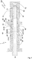
- Figure 1 shows an injection mold 100 with a multi-part core insert 1 rotationally symmetrical about a longitudinal axis 10, a neck ring 60 and a cavity insert 70 have a cylindrical structure.
- the fastening element 40 has an opening in the axial direction. However, the diameter of the opening varies in the axial direction in order to ensure a positive connection both with the upper core part 30 and with the lower core part 20.
- the lower core part 20 has an end section 21 protruding from the end face 26 in the axial direction, with two threaded bores 25 being embedded in the end section 21, which are used to fasten the fastening element 40 to the lower core part 20.
- the threaded bores 25 are arranged at an acute angle with respect to the longitudinal axis 10.
- the upper core part 30 is fixed to the lower core part 20 with the aid of the fastening element 40.
- the opening of the fastening element 40 at an end facing the lower core part 20 has a diameter such that the protruding end section 21 of the lower core part 20 can be received in a form-fitting manner.
- the fastening element 40 and the lower core insert 20 have two mutually perpendicular contact surface sections 27, 28, 47, 48, the contact surface sections 28, 48 being arranged parallel to the longitudinal axis 10 of the fastening element 40.
- the outer diameters of the lower core part 20 and of the fastening element 40 are selected so that their outer surfaces are flush.
- the opening of the fastening element 40 is also designed in such a way that the upper core part 30 can be received in the opening is.
- the upper core part 30 and the opening of the fastening element 40 have mutually corresponding stop surfaces 31, 42 which are conical in shape.
- a firm connection between the fastening element 40 and the upper core part 30 is achieved through the combination of mutually perpendicular contact surface sections and conical contact surfaces 31, 42. The same applies to the connection between the fastening element 40 and the lower core part 20, so that overall tilting of the upper core part 30 relative to the lower core part 20 is prevented.
- the multi-part core insert 1 has a cooling system.
- a cooling system for this purpose, there is a through-hole in the lower core part 20, in which a cooling liquid is guided.
- the upper core part 30 has a blind hole for guiding cooling liquid, the diameter of which corresponds to the diameter of the through hole of the lower core part 20.
- the upper core part 30 is arranged on the lower core part 20 in such a way that only two possible positions exist for the arrangement of the fastening element 40, the bores of the upper and lower core parts 20, 30 for guidance the coolant in any case flush with each other.
- the injection mold 100 has a mold space 80, the contour of which corresponds to the contour of the preform to be produced.
- the upper core insert 30 and the cavity insert 70 each have shape-forming sections 32, 71 which form part of the contour of the mold space 80.
- the other part of the mold space 80 is formed by a shape-forming section 61 of the neck ring 60, the shape-forming section 61 of the neck ring 60 being designed in such a way that a thread of a preform is formed.
- the neck ring has contact surfaces 63 which correspond to a frustoconical recess 45 of the fastening element 40 on an end 46 of the fastening element 40 facing away from the lower core part 20, so that the contact surfaces 63 of the neck ring 60 and the outer surface of the frustoconical recess 45 of the fastening element 40 are positively engaged with one another.
- the Neck ring 60 has contact surfaces 62 which are parallel to the longitudinal axis 10 and are in contact with the upper core part 30. As a result, the upper core insert 30 is additionally stabilized again.
- the cavity insert 70 has a gate 72 through which the plasticized melt is injected into the mold space 80 during the injection molding process, whereby a preform is formed.
- the cavity insert 70 and the neck ring 60 are removed by moving the components away from the multi-part core insert 1 in the axial direction.
- the preform initially remains on the core insert as in FIG Figure 2 shown.
- blow-out air is blown through blow-out channels 23, 24, 43, 44, which exerts a force on the preform parallel to the longitudinal axis 10, so that the preform is released from the upper core part 30.
- the blow-out channel 23 and the blow-out channel 24 of the lower core part 20 are arranged on opposite sides of the lower core part 20.
- the two blow-out channels 43, 44 of the fastening element 40 are directly connected to the blow-out channels 23, 24 of the lower core part 20 and are arranged between the through bores 49.
- the blow-out channels 43 and 44 of the fastening element 40 open into the recess 45 of the fastening element 40, which is located at an end 46 of the fastening element 40 facing away from the lower core part 20.
- the recess 45 is frustoconical.
- the openings of the blow-out channels 23, 24, 43, 44 lie directly one above the other in the direction of the longitudinal axis 10.
- the defined positioning is achieved by a locking pin 50.
- the material of the upper core part 30, the cavity insert 70 and the neck ring 60 is selected such that it has a particularly high thermal conductivity in order to cool the preform as quickly as possible.
- the sections of these components that form the mold space 80 are coated with a coating that makes it easier to detach the preform from the injection mold 100.
- the fastening element 40 and the lower core part 20, on the other hand, are made of a particularly robust steel that withstands the forces acting particularly well.
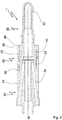
- Figure 3 shows an embodiment of a multi-part core insert 1, in which a different fastening mechanism for the fastening element 40 on the lower core part 20 has been selected.
- the reception of the upper core part 30 in the fastening element 40 can be configured as described above.
- an L-shaped recess 29 is arranged in the end section 21.
- the fastening element 40 also has a projection on the inner surface delimiting the recess in the radial direction, which protrudes into the L-shaped recess 29 when the fastening element 40 is pushed onto the lower core part 20 in the axial direction.
- the projection moves into the section of the L-shaped recess 29 aligned perpendicular to the longitudinal axis 10 and causes the fastening element 40 and the lower core part 20 to be clamped against one another.
Landscapes
- Engineering & Computer Science (AREA)
- Manufacturing & Machinery (AREA)
- Mechanical Engineering (AREA)
- Moulds For Moulding Plastics Or The Like (AREA)
- Injection Moulding Of Plastics Or The Like (AREA)
Applications Claiming Priority (1)
| Application Number | Priority Date | Filing Date | Title |
|---|---|---|---|
| DE102019134317.8A DE102019134317A1 (de) | 2019-12-13 | 2019-12-13 | Mehrteiliger Kerneinsatz |
Publications (1)
| Publication Number | Publication Date |
|---|---|
| EP3835026A1 true EP3835026A1 (fr) | 2021-06-16 |
Family
ID=73642571
Family Applications (1)
| Application Number | Title | Priority Date | Filing Date |
|---|---|---|---|
| EP20210163.0A Withdrawn EP3835026A1 (fr) | 2019-12-13 | 2020-11-27 | Insert de noyau en plusieurs parties |
Country Status (4)
| Country | Link |
|---|---|
| US (1) | US20210178647A1 (fr) |
| EP (1) | EP3835026A1 (fr) |
| CA (1) | CA3101564A1 (fr) |
| DE (1) | DE102019134317A1 (fr) |
Cited By (1)
| Publication number | Priority date | Publication date | Assignee | Title |
|---|---|---|---|---|
| EP4440808A4 (fr) * | 2021-11-29 | 2026-04-29 | Husky Injection Molding Systems Luxembourg Ip Dev Sarl | Moules, ensembles moules et composants d'empilage |
Citations (3)
| Publication number | Priority date | Publication date | Assignee | Title |
|---|---|---|---|---|
| KR101476060B1 (ko) * | 2013-11-19 | 2014-12-23 | 주식회사 엘지화학 | 엘보 파이프 제조용 금형장치 |
| CN206937831U (zh) * | 2017-04-27 | 2018-01-30 | 广东星联精密机械有限公司 | 瓶坯注塑模具的分体式模芯结构、瓶坯注塑模具及注模系统 |
| WO2019011969A1 (fr) | 2017-07-13 | 2019-01-17 | Mht Mold & Hotrunner Technology Ag | Insert de noyau en plusieurs parties |
Family Cites Families (3)
| Publication number | Priority date | Publication date | Assignee | Title |
|---|---|---|---|---|
| US20130216643A1 (en) * | 2010-11-08 | 2013-08-22 | Husky Injection Molding Systems Ltd | Split mold insert for forming a neck portion of a preform and the mold stack incorporating same |
| DE102015112223A1 (de) * | 2015-07-27 | 2017-02-02 | MHT IP GmbH | Spritzgießform mit Kernring |
| CN106926417B (zh) * | 2017-04-27 | 2023-01-10 | 广东星联精密机械有限公司 | 瓶胚注塑模具的分体式模芯结构、瓶坯注塑模具及注模系统 |
-
2019
- 2019-12-13 DE DE102019134317.8A patent/DE102019134317A1/de not_active Withdrawn
-
2020
- 2020-11-27 EP EP20210163.0A patent/EP3835026A1/fr not_active Withdrawn
- 2020-12-03 CA CA3101564A patent/CA3101564A1/fr active Pending
- 2020-12-09 US US17/116,387 patent/US20210178647A1/en not_active Abandoned
Patent Citations (3)
| Publication number | Priority date | Publication date | Assignee | Title |
|---|---|---|---|---|
| KR101476060B1 (ko) * | 2013-11-19 | 2014-12-23 | 주식회사 엘지화학 | 엘보 파이프 제조용 금형장치 |
| CN206937831U (zh) * | 2017-04-27 | 2018-01-30 | 广东星联精密机械有限公司 | 瓶坯注塑模具的分体式模芯结构、瓶坯注塑模具及注模系统 |
| WO2019011969A1 (fr) | 2017-07-13 | 2019-01-17 | Mht Mold & Hotrunner Technology Ag | Insert de noyau en plusieurs parties |
Cited By (1)
| Publication number | Priority date | Publication date | Assignee | Title |
|---|---|---|---|---|
| EP4440808A4 (fr) * | 2021-11-29 | 2026-04-29 | Husky Injection Molding Systems Luxembourg Ip Dev Sarl | Moules, ensembles moules et composants d'empilage |
Also Published As
| Publication number | Publication date |
|---|---|
| US20210178647A1 (en) | 2021-06-17 |
| CA3101564A1 (fr) | 2021-06-13 |
| DE102019134317A1 (de) | 2021-06-17 |
Similar Documents
| Publication | Publication Date | Title |
|---|---|---|
| DE60316444T2 (de) | Ventilnadelführungs- und -ausrichtungssystem für einen heisskanal in einer spritzgiessvorrichtung | |
| DE2166733A1 (de) | Spritz- blas-formwerkzeug fuer eine kunststoff-spritzgussmaschine | |
| DE3623099C3 (de) | Blasformmaschine | |
| DE102019107140A1 (de) | Düsenanordnung mit Druckreguliervorrichtung sowie Granuliervorrichtung | |
| EP2032329B1 (fr) | Cavité de moule avec canal de refroidissement en forme de méandre | |
| DE202019105683U1 (de) | Extrusionstechnik zur Bildung von Kunststoff-Vorformlingen und Profilierungstechnik | |
| EP3835026A1 (fr) | Insert de noyau en plusieurs parties | |
| DE102016219833A1 (de) | Spritzdüse für Kunststoffspritzgießvorrichtungen zur Herstellung von transparenten oder halbtransparenten ästhetischen Fahrzeugkomponenten, beispielsweise Linsen für Beleuchtung, und Spritzgießvorrichtung | |
| DE102018116828A1 (de) | Vorrichtung zum Spritzgießen von Kunststoffmaterialien | |
| EP1603729A1 (fr) | Buse de vanne pointeau | |
| DE10355018B4 (de) | Formnestaufbau | |
| WO2019011969A1 (fr) | Insert de noyau en plusieurs parties | |
| EP3609672B1 (fr) | Connecteur enfichable en matière plastique et procédé de fabrication associé | |
| DE19941160B4 (de) | Zylinder für einen Schneckenextruder mit Kanälen für ein Temperiermedium | |
| EP0932488B1 (fr) | Moule pour injection destine a des matieres elastomeres durcissables ou vulcanisables | |
| WO2005108044A1 (fr) | Outil de moulage par injection | |
| DE102011007553A1 (de) | Kühlhülse mit Stützelement | |
| DE102006004928A1 (de) | Verbesserte Halsbackenkühlung | |
| DE102006021228A1 (de) | Zweiteiliger Bodeneinsatz | |
| EP3231574A1 (fr) | Douille de guidage pour un dispositif de moulage par injection | |
| DE1911600B2 (de) | Mehrteilige Form zum Pressen oder Blasen von thermoplastischen Materialien | |
| EP2209601A2 (fr) | Buse de moulage par injection | |
| DE2354134A1 (de) | Verteiler zum spritzgiessen thermoempfindlicher kunststoffe in mehrfachformwerkzeuge | |
| DE19729828B4 (de) | Werkzeug zur Herstellung eines Mehrwegeventilgehäuses in Kunststoffspritzgießtechnik | |
| DE102013106331B4 (de) | Spritzgießwerkzeug zum Herstellen eines Formteils aus einem Kunststoff sowie Herstellungsverfahren des Formteils |
Legal Events
| Date | Code | Title | Description |
|---|---|---|---|
| PUAI | Public reference made under article 153(3) epc to a published international application that has entered the european phase |
Free format text: ORIGINAL CODE: 0009012 |
|
| STAA | Information on the status of an ep patent application or granted ep patent |
Free format text: STATUS: THE APPLICATION HAS BEEN PUBLISHED |
|
| AK | Designated contracting states |
Kind code of ref document: A1 Designated state(s): AL AT BE BG CH CY CZ DE DK EE ES FI FR GB GR HR HU IE IS IT LI LT LU LV MC MK MT NL NO PL PT RO RS SE SI SK SM TR |
|
| STAA | Information on the status of an ep patent application or granted ep patent |
Free format text: STATUS: REQUEST FOR EXAMINATION WAS MADE |
|
| 17P | Request for examination filed |
Effective date: 20211126 |
|
| RBV | Designated contracting states (corrected) |
Designated state(s): AL AT BE BG CH CY CZ DE DK EE ES FI FR GB GR HR HU IE IS IT LI LT LU LV MC MK MT NL NO PL PT RO RS SE SI SK SM TR |
|
| STAA | Information on the status of an ep patent application or granted ep patent |
Free format text: STATUS: EXAMINATION IS IN PROGRESS |
|
| GRAP | Despatch of communication of intention to grant a patent |
Free format text: ORIGINAL CODE: EPIDOSNIGR1 |
|
| STAA | Information on the status of an ep patent application or granted ep patent |
Free format text: STATUS: GRANT OF PATENT IS INTENDED |
|
| RIC1 | Information provided on ipc code assigned before grant |
Ipc: B29K 105/00 20060101ALN20230511BHEP Ipc: B29C 45/36 20060101ALI20230511BHEP Ipc: B29C 45/33 20060101ALI20230511BHEP Ipc: B29C 45/26 20060101AFI20230511BHEP |
|
| INTG | Intention to grant announced |
Effective date: 20230525 |
|
| STAA | Information on the status of an ep patent application or granted ep patent |
Free format text: STATUS: THE APPLICATION IS DEEMED TO BE WITHDRAWN |
|
| 18D | Application deemed to be withdrawn |
Effective date: 20231005 |