EP0932488B1 - Moule pour injection destine a des matieres elastomeres durcissables ou vulcanisables - Google Patents
Moule pour injection destine a des matieres elastomeres durcissables ou vulcanisables Download PDFInfo
- Publication number
- EP0932488B1 EP0932488B1 EP97918838A EP97918838A EP0932488B1 EP 0932488 B1 EP0932488 B1 EP 0932488B1 EP 97918838 A EP97918838 A EP 97918838A EP 97918838 A EP97918838 A EP 97918838A EP 0932488 B1 EP0932488 B1 EP 0932488B1
- Authority
- EP
- European Patent Office
- Prior art keywords
- nozzle
- injection
- tip
- mould according
- injection mould
- Prior art date
- Legal status (The legal status is an assumption and is not a legal conclusion. Google has not performed a legal analysis and makes no representation as to the accuracy of the status listed.)
- Expired - Lifetime
Links
- 238000002347 injection Methods 0.000 title claims abstract description 75
- 239000007924 injection Substances 0.000 title claims abstract description 75
- 239000000463 material Substances 0.000 title claims abstract description 16
- 229920001971 elastomer Polymers 0.000 title abstract description 4
- 239000000806 elastomer Substances 0.000 title abstract 2
- 238000000034 method Methods 0.000 claims description 2
- 238000000465 moulding Methods 0.000 abstract description 6
- 238000001816 cooling Methods 0.000 description 8
- 238000007789 sealing Methods 0.000 description 5
- 238000004519 manufacturing process Methods 0.000 description 4
- 239000002826 coolant Substances 0.000 description 2
- 230000007704 transition Effects 0.000 description 2
- 241000239290 Araneae Species 0.000 description 1
- 230000002411 adverse Effects 0.000 description 1
- 238000004140 cleaning Methods 0.000 description 1
- 238000004891 communication Methods 0.000 description 1
- 238000005516 engineering process Methods 0.000 description 1
- 238000002955 isolation Methods 0.000 description 1
- 229920001296 polysiloxane Polymers 0.000 description 1
- 238000000926 separation method Methods 0.000 description 1
- 239000007787 solid Substances 0.000 description 1
- 238000003860 storage Methods 0.000 description 1
- 239000002699 waste material Substances 0.000 description 1
Images

Classifications
-
- B—PERFORMING OPERATIONS; TRANSPORTING
- B29—WORKING OF PLASTICS; WORKING OF SUBSTANCES IN A PLASTIC STATE IN GENERAL
- B29C—SHAPING OR JOINING OF PLASTICS; SHAPING OF MATERIAL IN A PLASTIC STATE, NOT OTHERWISE PROVIDED FOR; AFTER-TREATMENT OF THE SHAPED PRODUCTS, e.g. REPAIRING
- B29C45/00—Injection moulding, i.e. forcing the required volume of moulding material through a nozzle into a closed mould; Apparatus therefor
- B29C45/17—Component parts, details or accessories; Auxiliary operations
- B29C45/26—Moulds
- B29C45/27—Sprue channels ; Runner channels or runner nozzles
- B29C45/278—Nozzle tips
-
- B—PERFORMING OPERATIONS; TRANSPORTING
- B29—WORKING OF PLASTICS; WORKING OF SUBSTANCES IN A PLASTIC STATE IN GENERAL
- B29C—SHAPING OR JOINING OF PLASTICS; SHAPING OF MATERIAL IN A PLASTIC STATE, NOT OTHERWISE PROVIDED FOR; AFTER-TREATMENT OF THE SHAPED PRODUCTS, e.g. REPAIRING
- B29C45/00—Injection moulding, i.e. forcing the required volume of moulding material through a nozzle into a closed mould; Apparatus therefor
- B29C45/17—Component parts, details or accessories; Auxiliary operations
- B29C45/26—Moulds
- B29C45/27—Sprue channels ; Runner channels or runner nozzles
- B29C45/2756—Cold runner channels
-
- B—PERFORMING OPERATIONS; TRANSPORTING
- B29—WORKING OF PLASTICS; WORKING OF SUBSTANCES IN A PLASTIC STATE IN GENERAL
- B29C—SHAPING OR JOINING OF PLASTICS; SHAPING OF MATERIAL IN A PLASTIC STATE, NOT OTHERWISE PROVIDED FOR; AFTER-TREATMENT OF THE SHAPED PRODUCTS, e.g. REPAIRING
- B29C45/00—Injection moulding, i.e. forcing the required volume of moulding material through a nozzle into a closed mould; Apparatus therefor
- B29C45/17—Component parts, details or accessories; Auxiliary operations
- B29C45/26—Moulds
- B29C45/27—Sprue channels ; Runner channels or runner nozzles
- B29C2045/2764—Limited contact between nozzle and mould
-
- B—PERFORMING OPERATIONS; TRANSPORTING
- B29—WORKING OF PLASTICS; WORKING OF SUBSTANCES IN A PLASTIC STATE IN GENERAL
- B29C—SHAPING OR JOINING OF PLASTICS; SHAPING OF MATERIAL IN A PLASTIC STATE, NOT OTHERWISE PROVIDED FOR; AFTER-TREATMENT OF THE SHAPED PRODUCTS, e.g. REPAIRING
- B29C45/00—Injection moulding, i.e. forcing the required volume of moulding material through a nozzle into a closed mould; Apparatus therefor
- B29C45/17—Component parts, details or accessories; Auxiliary operations
- B29C45/26—Moulds
- B29C45/27—Sprue channels ; Runner channels or runner nozzles
- B29C2045/2796—Axially movable nozzles or nozzle tips
- B29C2045/2798—Axially movable nozzles or nozzle tips for compensating thermal expansion
-
- B—PERFORMING OPERATIONS; TRANSPORTING
- B29—WORKING OF PLASTICS; WORKING OF SUBSTANCES IN A PLASTIC STATE IN GENERAL
- B29K—INDEXING SCHEME ASSOCIATED WITH SUBCLASSES B29B, B29C OR B29D, RELATING TO MOULDING MATERIALS OR TO MATERIALS FOR MOULDS, REINFORCEMENTS, FILLERS OR PREFORMED PARTS, e.g. INSERTS
- B29K2021/00—Use of unspecified rubbers as moulding material
- B29K2021/006—Thermosetting elastomers
-
- B—PERFORMING OPERATIONS; TRANSPORTING
- B29—WORKING OF PLASTICS; WORKING OF SUBSTANCES IN A PLASTIC STATE IN GENERAL
- B29K—INDEXING SCHEME ASSOCIATED WITH SUBCLASSES B29B, B29C OR B29D, RELATING TO MOULDING MATERIALS OR TO MATERIALS FOR MOULDS, REINFORCEMENTS, FILLERS OR PREFORMED PARTS, e.g. INSERTS
- B29K2083/00—Use of polymers having silicon, with or without sulfur, nitrogen, oxygen, or carbon only, in the main chain, as moulding material
- B29K2083/005—LSR, i.e. liquid silicone rubbers, or derivatives thereof
Definitions
- the invention relates to an injection mold with the features of The preamble of claim 1.
- an injection mold is known in which the Injection nozzle in an open connection with the mold cavity Antechamber opens at a distance from the mold nest.
- This injection mold the high technical effort for fitting the Cannula in the inlet opening of the mold cavity avoided, however it is difficult to change the heat flow in the area between To control the pre-chamber and mold cavity so that the injection molded part Demold from the plug that is in the antechamber and in the Entry opening forms, tears off smoothly so that no breakouts or Burrs remain on the injection molded part.
- the plug is then injected into the mold cavity and when the mold nest is filled again, a new one is formed Plug from which the injection molded part must be separated again.
- EP-A-0 323 330 is an injection nozzle for an injection mold disclosed.
- the injector is heated and the mold is cooled is therefore a so-called hot runner tool.
- the injector is received in a hole in a mold plate and is at the tip of an inlet hole in the mold plate seen in the flow direction initially conical tapered and then merges into a cylindrical part that fits into the Form nest opens.
- the injection channel is therefore continuous, i.e. without a jump in diameter, from the larger pressure meter in the injector mouth in the conical and then cylindrical part of the Inlet bore above.
- In the area of the injector mouth and the Inlet bores are arranged with the injection nozzle are connected to control the temperature balance in this area to be able to.
- a hot runner tool is also described in US Pat. No. 3,677,682, the one injector with one nozzle body and one in it has displaceable nozzle tip.
- the nozzle tip is made of disc springs, which is clamped between the nozzle tip and the nozzle body are in the area of a conical hole in the mold cavity opens, pressed against the mold plate. The nozzle tip opens directly in the mold nest.
- a cold runner tool which has an injection nozzle with a nozzle body and a nozzle tip that can be moved therein having.
- the tip of the nozzle is supported by disc springs between the Nozzle tip and the nozzle body are clamped in the area of a Entry hole in the mold cavity pressed against the mold plate.
- the Diameter of the tip bore of the nozzle tip and the inlet bore are in the transition area, i.e. in the area of the confluence of the Tip hole in the entry hole, the same size.
- the invention has for its object an injection mold to create the type mentioned, which has the disadvantages of Does not have the prior art.
- the injection mold according to the invention has EP 162 037 A the advantage that no cannula must be used, the under high technical effort in the entrance opening of the mold nest must be fitted.
- the force which the injector presses against the mold plate a sufficiently high Force applied to the seal opposite the annulus between to ensure the nozzle tip and the molding plate.
- the injection nozzle and / or their Nozzle tip are mounted axially displaceable, then also on simple way ensures that if it is due to Temperature fluctuations of the mold plate and / or the injector too Changes in length come, which means the exact positioning of the nozzle tip in the area of the inlet opening or the seal between the nozzle tip and the molding plate could deteriorate them be compensated for by the displaceability and the injection nozzle and in particular their nozzle tip with a substantially constant Force is constantly pressed against the mold plate.
- Another advantage that arises is that dimensional deviations balanced in the manufacture of the injector and the mold plate can be, whereby the production of the invention Simplify injection mold and make it cheaper.
- a preferred embodiment of the invention is characterized in that that the injection nozzle or its nozzle tip through the Force is pressed against the mold plate by a spring.
- the spring is a plate spring. It but is also any other type of spring or spring-like device possible using the injection nozzle in the area of the nozzle tip a force that is preferably permanent and essentially constant is pressed against the mold plate, so that a sufficient seal is guaranteed.
- wear tips that can be removed from the injector often come used to mold the injection mold onto other or converting vulcanizing, elastomeric materials.
- the spring between the injector nozzle body and the wear tip is arranged and that the wear tip axially is slidably mounted in the nozzle body.
- the spring is supported on the one hand on the nozzle body and on the other hand on the wear tip and press the latter against the mold plate in the area of the inlet bore.
- injection molds have two mold plates 1 and 2, which enclose a mold cavity 6 and be heated.
- On the back of the mold plate 2 is an insulating plate 3 provided.
- a cooling plate connects to the insulating plate 3 5 on, in which an injection nozzle 8 'is mounted.
- the injection nozzle 8 has a nozzle body 8, via which one Sleeve 13 is pushed, the cooling channels 14 closes to the outside are provided on the outer wall of the nozzle body 8.
- the cooling channels 14 are in communication with holes 4 in the cooling plate 5 which coolant is supplied or removed.
- a sealing ring 10 is provided in Fig. 1.
- a wear tip 15 in the axial Slidably supported in the direction.
- the wear tip 15 a cylindrical guide member 23 arranged in a cylindrical Bore 26 in the nozzle body 8 axially slidably received is.
- this cylindrical guide part 23 there is a nozzle cone 24 arranged, the transition between an injection bore 17 and the bore 26 with a larger diameter in the nozzle body 8 to a Tip bore 16 with a smaller diameter in the wear tip 15 forms.
- a plate spring 7 which the Wear tip 15 constantly against the contact surface 21 on the mold plate 2 presses.
- a plate spring 7 can of course also any other spring element can be used that this Purpose accomplished.
- the nozzle tip 22 becomes the wear tip 15 constantly against the contact surface 21 in the area of the inlet bore 18 pressed, whereby the inlet bore 18 against one after rear annular space 12 is sealed between the Insulating plate 3 and the mold plate 2 and the injection nozzle 8 ' Isolation purposes is provided.
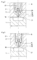
- the shape of the contact between the nozzle tip 22 and the contact surface 21 can be implemented in different ways.
- FIG 3 in turn shows an embodiment in which the end face of the nozzle tip 22 and the contact surface 21 flat and aligned at right angles to the longitudinal axis of the injector 8 ' are.
- FIGS. 2 and 4 have in common that the nozzle tip 22 automatically on the mold plate 2 in the area of Entry hole 18 centered so that it does not become a lateral Offset between the nozzle mouth and the inlet bore 18 can come.
- Embodiments can also be provided that the nozzle tip 22nd conical and the contact surface 21 of the mold plate 2 inwards, i.e. towards the nozzle tip 21, is rounded in a curved manner.
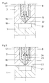
- FIG 5 shows an alternative embodiment of the invention, in which the spring 7 by a resilient sealing ring 34 is replaced.
- This sealing ring 34 presses the wear tip 15 constantly against the contact surface 21 and creates at the same time also a seal between the guide part 23, which in this case is still extended into the injection bore 17, and the nozzle body 8th.
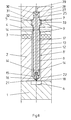
- FIG. 6 Another alternative embodiment of the invention is shown in FIG. 6 shown, in which the entire injector 8 'in the cooling plate 5 and the mold plate 2 slidably supported and by a spring 7 is pressed towards the mold nest 6, which in the rear area of the Injection nozzle 8 'is arranged.
- a holding plate 27 behind the cooling plate 5 arranged in which the rear end of the injector 8 'in a Bore 28 is slidably received.
- the injection material is the injection bore 17 via a feed channel 29, the bore 28 and a funnel-shaped extension 30 is supplied.
- a sealing ring 25 provided to seal the Nozzle body 8 'opposite the holding plate 27 is in turn a sealing ring 25 provided.
- a plate spring 7 provided in an annular Recess 31 of the holding plate 27 is received and against it supported.
- the holding plate 27 is opposite on the nozzle body 8 a widened extension 32 is provided, which has a support surface 33 forms, against which the plate spring is also supported.
- the injector 8 ' is therefore, since it is axially displaceable, by the Disc spring 7 with permanent force against the contact surface 21 on the Entry opening 18 pressed.
Landscapes
- Engineering & Computer Science (AREA)
- Manufacturing & Machinery (AREA)
- Mechanical Engineering (AREA)
- Moulds For Moulding Plastics Or The Like (AREA)
Abstract
Claims (14)
- Moule pour le moulage par injection selon la technique dite à canal froid, pour des matériaux élastomères thermodurcissables ou vulcanisables à chaud, comprenant une cavité de moule (6) délimitée par des plaques de moule (1, 2) chauffées et une buse d'injection (8'), avec un nez de buse (22) pourvu d'un trou (16), qui est à une température inférieure à celle des plaques de moule (1, 2) et qui, dans la région de la cavité de moule (6), débouche dans un orifice d'entrée (18) de la cavité de moule (6), prévu dans l'une desdites plaque moule (2), le nez de buse (22) étant appliqué contre la plaque de moule (2) par l'action d'une force qui agit en direction de la cavité de moule (6), caractérisé en ce que le trou (16) dans le nez de la buse d'injection (8'), dans la région du débouché dans l'orifice d'entrée (18), présente un diamètre supérieur à celui de l'orifice d'entrée (18).
- Moule de moulage par injection selon la revendication 1, caractérisé en ce que la buse d'injection (8') ou le nez (22) de celle-ci est monté coulissant dans la direction axiale.
- Moule de moulage par injection selon la revendication 1 ou 2, caractérisé en ce que le nez (22) de la buse d'injection, dans la zone contiguë ou voisine de l'orifice d'entrée (18), est appliqué contre la plaque de moule (2).
- Moule de moulage par injection selon une des revendications 1 à 3, caractérisé en ce que la buse d'injection (8') et/ou le nez (22) de celle-ci est pressé contre la plaque de moule (2) par la force d'un ressort (7, 34).
- Moule de moulage par injection selon la revendication 4, caractérisé en ce que le ressort (7) est une rondelle-ressort.
- Moule de moulage par injection selon une des revendications 1 à 5, caractérisé en ce que la buse d'injection (8') présente une pièce d'usure d'extrémité (15) sur laquelle le nez de buse (22) est disposé.
- Moule de moulage par injection selon une des revendications 4 et 6, caractérisé en ce que le ressort (7) est disposé entre le corps (8) de la buse d'injection (8') et la pièce d'usure d'extrémité (15) et en ce que la pièce d'usure d'extrémité (15) est montée coulissante dans la direction axiale dans le corps de buse (8).
- Moule de moulage par injection selon la revendication 7, caractérisé en ce que la pièce d'usure d'extrémité (15) comporte une partie de guidage (23) cylindrique, qui est montée coulissante dans la direction axiale dans le corps de buse (8).
- Moule de moulage par injection selon la revendication 8, caractérisé en ce que l'espace entre la paroi du trou (26) dans le corps de buse (8) et la partie de guidage (23) est étanché par un joint d'étanchéité (25) qui, de préférence, est monté dans une gorge annulaire dans la partie de guidage (23).
- Moule de moulage par injection selon la revendication 4, caractérisé en ce que sur le corps (8) de la buse d'injection (8') est prévue une surface d'appui (33) sur laquelle le ressort (7) prend appui.
- Moule de moulage par injection selon une des revendications 1 à 10, caractérisé en ce qu'une surface de contact (21) pour le nez de buse (22) sur la plaque de moule (2) et la surface du nez de buse (22) tournée vers la surface de contact (21) sont planes et sont disposées à angle droit par rapport à l'axe longitudinal de la buse d'injection (8').
- Moule de moulage par injection selon une des revendications 1 à 10, caractérisé en ce que le nez de buse (22) et une surface de contact (21) pour le nez de buse (22) sur la plaque de moule (2) sont arrondis de manière congruente.
- Moule de moulage par injection selon une des revendications 1 à 10, caractérisé en ce que le nez de buse (22) et une surface de contact (21) pour le nez de buse (22) sur la plaque de moule (2) sont conformés en cône.
- Moule de moulage par injection selon une des revendications 1 à 13, caractérisé en ce que la buse d'injection (8') débouche à distance de la cavité de moule (6).
Priority Applications (1)
| Application Number | Priority Date | Filing Date | Title |
|---|---|---|---|
| AT97918838T ATE240198T1 (de) | 1996-09-18 | 1997-09-16 | Spritzgussform für aushärtbare oder vulkanisierende, elastomere materialien |
Applications Claiming Priority (3)
| Application Number | Priority Date | Filing Date | Title |
|---|---|---|---|
| AT165296 | 1996-09-18 | ||
| AT165296 | 1996-09-18 | ||
| PCT/AT1997/000203 WO1998012038A1 (fr) | 1996-09-18 | 1997-09-16 | Moule pour injection destine a des matieres elastomeres durcissables ou vulcanisables |
Publications (2)
| Publication Number | Publication Date |
|---|---|
| EP0932488A1 EP0932488A1 (fr) | 1999-08-04 |
| EP0932488B1 true EP0932488B1 (fr) | 2003-05-14 |
Family
ID=3518052
Family Applications (1)
| Application Number | Title | Priority Date | Filing Date |
|---|---|---|---|
| EP97918838A Expired - Lifetime EP0932488B1 (fr) | 1996-09-18 | 1997-09-16 | Moule pour injection destine a des matieres elastomeres durcissables ou vulcanisables |
Country Status (4)
| Country | Link |
|---|---|
| EP (1) | EP0932488B1 (fr) |
| AU (1) | AU4290297A (fr) |
| DE (1) | DE59710096D1 (fr) |
| WO (1) | WO1998012038A1 (fr) |
Cited By (2)
| Publication number | Priority date | Publication date | Assignee | Title |
|---|---|---|---|---|
| US8899964B2 (en) | 2012-03-16 | 2014-12-02 | Mold-Masters (2007) Limited | Edge-gated injection molding apparatus |
| US8932046B2 (en) | 2012-03-16 | 2015-01-13 | Mold-Masters (2007) Limited | Edge-gated injection molding apparatus |
Families Citing this family (7)
| Publication number | Priority date | Publication date | Assignee | Title |
|---|---|---|---|---|
| ATA193996A (de) * | 1996-11-06 | 2000-09-15 | Elmet Elastomere Produktions U | Spritzgussform |
| ES2173720T3 (es) | 1999-02-18 | 2002-10-16 | Elast Kunststoffverarbeitungs | Tobera de inyeccion. |
| NL1012925C2 (nl) | 1999-08-27 | 2001-02-28 | Franciscus Antonius Jozef Van | Spuitgietinrichting. |
| DE60314058T2 (de) * | 2002-07-30 | 2008-01-31 | Rutil S.R.L. | Ein Spritzgiesssystem für ein durch Wärme vulkanisierbares Material |
| NL1024099C1 (nl) * | 2003-08-13 | 2005-02-15 | Guenther Herbert Gmbh | Spuitgiet-injecteur met losse spuitkop. |
| FR2892968A1 (fr) * | 2005-11-04 | 2007-05-11 | Creations Nivernaises E C N Sa | Dispositif d'injection-moulage d'une matiere thermoplastique |
| DE102013014883A1 (de) * | 2013-09-06 | 2015-03-12 | Braunform Gmbh | Kaltkanal-Schmelzeverteiler |
Family Cites Families (7)
| Publication number | Priority date | Publication date | Assignee | Title |
|---|---|---|---|---|
| US3553788A (en) * | 1968-09-10 | 1971-01-12 | Ladislao Wladyslaw Putkowski | Hot runner system for plastic injection molds |
| US3677682A (en) * | 1970-03-09 | 1972-07-18 | Ladislao Wladyslaw Putkowski | Hot runner system |
| US3843295A (en) * | 1973-05-24 | 1974-10-22 | Bischoff Chemical Corp | Injection molding machine with adjustable nozzle length means |
| FR2625133B1 (fr) * | 1987-12-24 | 1990-09-21 | Delta Projet | Buse de moule pour injection de matiere plastique |
| US5098280A (en) * | 1990-09-26 | 1992-03-24 | Panos Trakas | Sprue bushing with displaceable gating needle |
| US5849344A (en) * | 1994-09-28 | 1998-12-15 | Meiho Co., Ltd. | Injection molding apparatus |
| US5609893A (en) * | 1995-01-12 | 1997-03-11 | Jk Molds, Inc. | Probe assembly for injection molding apparatus |
-
1997
- 1997-09-16 EP EP97918838A patent/EP0932488B1/fr not_active Expired - Lifetime
- 1997-09-16 WO PCT/AT1997/000203 patent/WO1998012038A1/fr not_active Ceased
- 1997-09-16 AU AU42902/97A patent/AU4290297A/en not_active Abandoned
- 1997-09-16 DE DE59710096T patent/DE59710096D1/de not_active Expired - Lifetime
Cited By (3)
| Publication number | Priority date | Publication date | Assignee | Title |
|---|---|---|---|---|
| US8899964B2 (en) | 2012-03-16 | 2014-12-02 | Mold-Masters (2007) Limited | Edge-gated injection molding apparatus |
| US8932046B2 (en) | 2012-03-16 | 2015-01-13 | Mold-Masters (2007) Limited | Edge-gated injection molding apparatus |
| US9694525B2 (en) | 2012-03-16 | 2017-07-04 | Mold-Master (2007) Limited | Edge-gated injection molding apparatus |
Also Published As
| Publication number | Publication date |
|---|---|
| EP0932488A1 (fr) | 1999-08-04 |
| DE59710096D1 (de) | 2003-06-18 |
| AU4290297A (en) | 1998-04-14 |
| WO1998012038A1 (fr) | 1998-03-26 |
Similar Documents
| Publication | Publication Date | Title |
|---|---|---|
| EP0162037B1 (fr) | Procédé pour la fabrication de pièces moulées par injection et moule par injection correspondant | |
| DE69311247T2 (de) | Abgedichtete, seitliche Angussöffnung | |
| DE60316444T2 (de) | Ventilnadelführungs- und -ausrichtungssystem für einen heisskanal in einer spritzgiessvorrichtung | |
| EP3153294B1 (fr) | Outil de moulage par injection | |
| DE69603146T2 (de) | Spritzgiesstorpedo aus Karbid | |
| EP0671249B1 (fr) | Procédé et dispositif pour la fabrication de lentilles optiques | |
| DE68905213T2 (de) | Spritzgiesssystem mit duese in tandem. | |
| DE69603538T2 (de) | Spritzgiessvorrichtung mit seitlichem Anschnitt mit radial montierten Anschnitteinsätzen | |
| DE69106811T2 (de) | Isolierende und elastische Distanzscheibe für Spritzgussformen. | |
| EP0932488B1 (fr) | Moule pour injection destine a des matieres elastomeres durcissables ou vulcanisables | |
| EP2303539A2 (fr) | Buse d'injection pour moule d'injection | |
| DE19611213A1 (de) | Pressformvorrichtung zur Herstellung von Verbundisolatoren | |
| DE10355018B4 (de) | Formnestaufbau | |
| EP1603729A1 (fr) | Buse de vanne pointeau | |
| EP0841142B1 (fr) | Moule d'injection | |
| DE602004009632T2 (de) | Spritzgiess-Heisskanal-Düse mit abnehmbarem Düsenkopf und Düsenkopfhalterung und Verfahren zur Herstellung einer Spritzgiess-Heisskanal-Düse | |
| DE3143748C2 (de) | Form zum Spritzgießen oder Preßspritzen von Kautschuk oder anderen plastischen, wärmehärtbaren Werkstoffen | |
| EP3609672A1 (fr) | Connecteur enfichable en matière plastique et procédé de fabrication associé | |
| EP0992332B1 (fr) | Fermeture des canaux chauds | |
| EP1599328A1 (fr) | Procede de production d'articles moules par injection et buse a obturation a aiguille pour moule a injection | |
| DE102022103681B3 (de) | Seitenangussdüse, spitzeneinsatz für eine seitenangussdüse und spritzgiessform | |
| DE102019127956A1 (de) | Seitenanspritzdüse und spritzgiesswerkzeug | |
| EP2209601A2 (fr) | Buse de moulage par injection | |
| EP1922202A1 (fr) | Dispositif de moulage par injection dote d'une douille d'obturateur a aiguille et d'une douille de guidage | |
| DE102022105317A1 (de) | Einsatz für eine Spritzgießdüse und Spritzgießdüse mit einem solchen Einsatz |
Legal Events
| Date | Code | Title | Description |
|---|---|---|---|
| PUAI | Public reference made under article 153(3) epc to a published international application that has entered the european phase |
Free format text: ORIGINAL CODE: 0009012 |
|
| 17P | Request for examination filed |
Effective date: 19990419 |
|
| AK | Designated contracting states |
Kind code of ref document: A1 Designated state(s): AT BE CH DE DK ES FI FR GB GR IE IT LI LU MC NL PT SE |
|
| AX | Request for extension of the european patent |
Free format text: SI PAYMENT 19990419 |
|
| 17Q | First examination report despatched |
Effective date: 20010301 |
|
| GRAH | Despatch of communication of intention to grant a patent |
Free format text: ORIGINAL CODE: EPIDOS IGRA |
|
| GRAH | Despatch of communication of intention to grant a patent |
Free format text: ORIGINAL CODE: EPIDOS IGRA |
|
| GRAA | (expected) grant |
Free format text: ORIGINAL CODE: 0009210 |
|
| AK | Designated contracting states |
Designated state(s): AT BE CH DE DK ES FI FR GB GR IE IT LI LU MC NL PT SE |
|
| AX | Request for extension of the european patent |
Extension state: SI |
|
| PG25 | Lapsed in a contracting state [announced via postgrant information from national office to epo] |
Ref country code: NL Free format text: LAPSE BECAUSE OF FAILURE TO SUBMIT A TRANSLATION OF THE DESCRIPTION OR TO PAY THE FEE WITHIN THE PRESCRIBED TIME-LIMIT Effective date: 20030514 Ref country code: IE Free format text: LAPSE BECAUSE OF FAILURE TO SUBMIT A TRANSLATION OF THE DESCRIPTION OR TO PAY THE FEE WITHIN THE PRESCRIBED TIME-LIMIT Effective date: 20030514 Ref country code: GB Free format text: LAPSE BECAUSE OF FAILURE TO SUBMIT A TRANSLATION OF THE DESCRIPTION OR TO PAY THE FEE WITHIN THE PRESCRIBED TIME-LIMIT Effective date: 20030514 Ref country code: FI Free format text: LAPSE BECAUSE OF FAILURE TO SUBMIT A TRANSLATION OF THE DESCRIPTION OR TO PAY THE FEE WITHIN THE PRESCRIBED TIME-LIMIT Effective date: 20030514 |
|
| REG | Reference to a national code |
Ref country code: GB Ref legal event code: FG4D Free format text: NOT ENGLISH |
|
| REG | Reference to a national code |
Ref country code: CH Ref legal event code: EP |
|
| REG | Reference to a national code |
Ref country code: IE Ref legal event code: FG4D Free format text: GERMAN |
|
| RAP2 | Party data changed (patent owner data changed or rights of a patent transferred) |
Owner name: HEFNER ELASTOMERE-TECHNIK GMBH |
|
| REF | Corresponds to: |
Ref document number: 59710096 Country of ref document: DE Date of ref document: 20030618 Kind code of ref document: P |
|
| NLT2 | Nl: modifications (of names), taken from the european patent patent bulletin |
Owner name: HEFNER ELASTOMERE-TECHNIK GMBH |
|
| PG25 | Lapsed in a contracting state [announced via postgrant information from national office to epo] |
Ref country code: SE Free format text: LAPSE BECAUSE OF FAILURE TO SUBMIT A TRANSLATION OF THE DESCRIPTION OR TO PAY THE FEE WITHIN THE PRESCRIBED TIME-LIMIT Effective date: 20030814 Ref country code: PT Free format text: LAPSE BECAUSE OF FAILURE TO SUBMIT A TRANSLATION OF THE DESCRIPTION OR TO PAY THE FEE WITHIN THE PRESCRIBED TIME-LIMIT Effective date: 20030814 Ref country code: GR Free format text: LAPSE BECAUSE OF FAILURE TO SUBMIT A TRANSLATION OF THE DESCRIPTION OR TO PAY THE FEE WITHIN THE PRESCRIBED TIME-LIMIT Effective date: 20030814 Ref country code: DK Free format text: LAPSE BECAUSE OF FAILURE TO SUBMIT A TRANSLATION OF THE DESCRIPTION OR TO PAY THE FEE WITHIN THE PRESCRIBED TIME-LIMIT Effective date: 20030814 |
|
| PG25 | Lapsed in a contracting state [announced via postgrant information from national office to epo] |
Ref country code: ES Free format text: LAPSE BECAUSE OF FAILURE TO SUBMIT A TRANSLATION OF THE DESCRIPTION OR TO PAY THE FEE WITHIN THE PRESCRIBED TIME-LIMIT Effective date: 20030825 |
|
| PG25 | Lapsed in a contracting state [announced via postgrant information from national office to epo] |
Ref country code: LU Free format text: LAPSE BECAUSE OF NON-PAYMENT OF DUE FEES Effective date: 20030916 |
|
| PG25 | Lapsed in a contracting state [announced via postgrant information from national office to epo] |
Ref country code: MC Free format text: LAPSE BECAUSE OF NON-PAYMENT OF DUE FEES Effective date: 20030930 Ref country code: BE Free format text: LAPSE BECAUSE OF NON-PAYMENT OF DUE FEES Effective date: 20030930 |
|
| NLV1 | Nl: lapsed or annulled due to failure to fulfill the requirements of art. 29p and 29m of the patents act | ||
| GBV | Gb: ep patent (uk) treated as always having been void in accordance with gb section 77(7)/1977 [no translation filed] |
Effective date: 20030514 |
|
| REG | Reference to a national code |
Ref country code: IE Ref legal event code: FD4D Ref document number: 0932488E Country of ref document: IE |
|
| ET | Fr: translation filed | ||
| PLBE | No opposition filed within time limit |
Free format text: ORIGINAL CODE: 0009261 |
|
| STAA | Information on the status of an ep patent application or granted ep patent |
Free format text: STATUS: NO OPPOSITION FILED WITHIN TIME LIMIT |
|
| BERE | Be: lapsed |
Owner name: *HEFNER G.M.B.H. ELASTOMERE VERARBEITUNG Effective date: 20030930 |
|
| 26N | No opposition filed |
Effective date: 20040217 |
|
| REG | Reference to a national code |
Ref country code: CH Ref legal event code: PL |
|
| REG | Reference to a national code |
Ref country code: CH Ref legal event code: AEN Free format text: DAS PATENT IST AUFGRUND DES WEITERBEHANDLUNGSANTRAGS VOM 25.06.2004 REAKTIVIERT WORDEN. |
|
| REG | Reference to a national code |
Ref country code: CH Ref legal event code: PL |
|
| PGFP | Annual fee paid to national office [announced via postgrant information from national office to epo] |
Ref country code: CH Payment date: 20060802 Year of fee payment: 9 |
|
| REG | Reference to a national code |
Ref country code: CH Ref legal event code: AEN Free format text: DAS PATENT IST AUFGRUND DES WEITERBEHANDLUNGSANTRAGS VOM 15.05.2006 REAKTIVIERT WORDEN. |
|
| PG25 | Lapsed in a contracting state [announced via postgrant information from national office to epo] |
Ref country code: LI Free format text: LAPSE BECAUSE OF NON-PAYMENT OF DUE FEES Effective date: 20060930 Ref country code: CH Free format text: LAPSE BECAUSE OF NON-PAYMENT OF DUE FEES Effective date: 20060930 |
|
| REG | Reference to a national code |
Ref country code: CH Ref legal event code: PL |
|
| PGFP | Annual fee paid to national office [announced via postgrant information from national office to epo] |
Ref country code: AT Payment date: 20100831 Year of fee payment: 14 |
|
| REG | Reference to a national code |
Ref country code: DE Ref legal event code: R082 Ref document number: 59710096 Country of ref document: DE Representative=s name: PATENTANWAELTE HENKEL, BREUER & PARTNER, DE |
|
| REG | Reference to a national code |
Ref country code: AT Ref legal event code: MM01 Ref document number: 240198 Country of ref document: AT Kind code of ref document: T Effective date: 20110916 |
|
| PG25 | Lapsed in a contracting state [announced via postgrant information from national office to epo] |
Ref country code: AT Free format text: LAPSE BECAUSE OF NON-PAYMENT OF DUE FEES Effective date: 20110916 |
|
| REG | Reference to a national code |
Ref country code: FR Ref legal event code: PLFP Year of fee payment: 19 |
|
| REG | Reference to a national code |
Ref country code: FR Ref legal event code: PLFP Year of fee payment: 20 |
|
| PGFP | Annual fee paid to national office [announced via postgrant information from national office to epo] |
Ref country code: FR Payment date: 20160928 Year of fee payment: 20 |
|
| PGFP | Annual fee paid to national office [announced via postgrant information from national office to epo] |
Ref country code: DE Payment date: 20160928 Year of fee payment: 20 |
|
| PGFP | Annual fee paid to national office [announced via postgrant information from national office to epo] |
Ref country code: IT Payment date: 20160926 Year of fee payment: 20 |
|
| REG | Reference to a national code |
Ref country code: DE Ref legal event code: R071 Ref document number: 59710096 Country of ref document: DE |