EP3835172A1 - Lenkrollenbremsvorrichtung - Google Patents
Lenkrollenbremsvorrichtung Download PDFInfo
- Publication number
- EP3835172A1 EP3835172A1 EP20804421.4A EP20804421A EP3835172A1 EP 3835172 A1 EP3835172 A1 EP 3835172A1 EP 20804421 A EP20804421 A EP 20804421A EP 3835172 A1 EP3835172 A1 EP 3835172A1
- Authority
- EP
- European Patent Office
- Prior art keywords
- cable
- lever
- caster
- roller
- brake device
- Prior art date
- Legal status (The legal status is an assumption and is not a legal conclusion. Google has not performed a legal analysis and makes no representation as to the accuracy of the status listed.)
- Granted
Links
Images





Classifications
-
- B—PERFORMING OPERATIONS; TRANSPORTING
- B60—VEHICLES IN GENERAL
- B60B—VEHICLE WHEELS; CASTORS; AXLES FOR WHEELS OR CASTORS; INCREASING WHEEL ADHESION
- B60B33/00—Castors in general ; Anti-clogging castors
- B60B33/0078—Castors in general ; Anti-clogging castors characterised by details of the wheel braking mechanism
- B60B33/0086—Castors in general ; Anti-clogging castors characterised by details of the wheel braking mechanism acting on rim or side portion of tyre
-
- B—PERFORMING OPERATIONS; TRANSPORTING
- B60—VEHICLES IN GENERAL
- B60B—VEHICLE WHEELS; CASTORS; AXLES FOR WHEELS OR CASTORS; INCREASING WHEEL ADHESION
- B60B33/00—Castors in general ; Anti-clogging castors
- B60B33/0078—Castors in general ; Anti-clogging castors characterised by details of the wheel braking mechanism
- B60B33/0092—Castors in general ; Anti-clogging castors characterised by details of the wheel braking mechanism actuated remotely, e.g. by cable or electrically
-
- B—PERFORMING OPERATIONS; TRANSPORTING
- B62—LAND VEHICLES FOR TRAVELLING OTHERWISE THAN ON RAILS
- B62B—HAND-PROPELLED VEHICLES, e.g. HAND CARTS OR PERAMBULATORS; SLEDGES
- B62B5/00—Accessories or details specially adapted for hand carts
- B62B5/04—Braking mechanisms; Locking devices against movement
- B62B5/0404—Braking mechanisms; Locking devices against movement automatic
- B62B5/0414—Braking mechanisms; Locking devices against movement automatic dead man's brakes
-
- B—PERFORMING OPERATIONS; TRANSPORTING
- B62—LAND VEHICLES FOR TRAVELLING OTHERWISE THAN ON RAILS
- B62B—HAND-PROPELLED VEHICLES, e.g. HAND CARTS OR PERAMBULATORS; SLEDGES
- B62B5/00—Accessories or details specially adapted for hand carts
- B62B5/04—Braking mechanisms; Locking devices against movement
- B62B5/0438—Braking mechanisms; Locking devices against movement hand operated
-
- B—PERFORMING OPERATIONS; TRANSPORTING
- B62—LAND VEHICLES FOR TRAVELLING OTHERWISE THAN ON RAILS
- B62B—HAND-PROPELLED VEHICLES, e.g. HAND CARTS OR PERAMBULATORS; SLEDGES
- B62B5/00—Accessories or details specially adapted for hand carts
- B62B5/04—Braking mechanisms; Locking devices against movement
- B62B5/0457—Braking mechanisms; Locking devices against movement by locking in a braking position
- B62B5/0461—Braking mechanisms; Locking devices against movement by locking in a braking position with positive engagement
-
- B—PERFORMING OPERATIONS; TRANSPORTING
- B60—VEHICLES IN GENERAL
- B60B—VEHICLE WHEELS; CASTORS; AXLES FOR WHEELS OR CASTORS; INCREASING WHEEL ADHESION
- B60B2200/00—Type of product being used or applied
- B60B2200/40—Articles of daily use
- B60B2200/43—Carts
-
- B—PERFORMING OPERATIONS; TRANSPORTING
- B60—VEHICLES IN GENERAL
- B60B—VEHICLE WHEELS; CASTORS; AXLES FOR WHEELS OR CASTORS; INCREASING WHEEL ADHESION
- B60B2900/00—Purpose of invention
- B60B2900/30—Increase in
- B60B2900/331—Safety or security
- B60B2900/3312—Safety or security during regular use
-
- B—PERFORMING OPERATIONS; TRANSPORTING
- B62—LAND VEHICLES FOR TRAVELLING OTHERWISE THAN ON RAILS
- B62B—HAND-PROPELLED VEHICLES, e.g. HAND CARTS OR PERAMBULATORS; SLEDGES
- B62B2301/00—Wheel arrangements; Steering; Stability; Wheel suspension
- B62B2301/04—Wheel arrangements; Steering; Stability; Wheel suspension comprising a wheel pivotable about a substantially vertical axis, e.g. swivelling castors
- B62B2301/044—Wheel arrangements; Steering; Stability; Wheel suspension comprising a wheel pivotable about a substantially vertical axis, e.g. swivelling castors arranged remote from the longitudinal centreline of the hand propelled vehicle
-
- B—PERFORMING OPERATIONS; TRANSPORTING
- B62—LAND VEHICLES FOR TRAVELLING OTHERWISE THAN ON RAILS
- B62B—HAND-PROPELLED VEHICLES, e.g. HAND CARTS OR PERAMBULATORS; SLEDGES
- B62B3/00—Hand carts having more than one axis carrying transport wheels; Steering devices therefor; Equipment therefor
- B62B3/002—Hand carts having more than one axis carrying transport wheels; Steering devices therefor; Equipment therefor characterised by a rectangular shape, involving sidewalls or racks
Definitions
- the present invention relates to a brake device for a caster.
- a brake device for a caster in which a brake shoe is disposed at a frame (fork), and an operation body is inserted and fitted in a hole drilled in the top panel of a frame, and the operation body is operated synchronously via a transfer means constituted of a cam, a link rod, and the like connected to a brake operation lever.
- the brake shoe is brought into contact with the circumferential surface of a roller so that the roller is braked by frictional resistance caused by the contact. For this reason, the braking effect may be reduced, and the circumferential surface of the roller may be damaged.
- the present invention was completed in view of the problem in the background art. It is an object of the present invention to provide a break device for a caster, which has a simple structure, provides reliable braking, has no risk of damaging the circumferential surface of a roller, and has high durability.
- the present invention provides a brake device for a caster according to [1] to [5] below.
- the claw of the lever is engaged with the projecting part formed at the side-surface of the roller, thereby applying brake to the roller. Accordingly, a reliable braking effect can be obtained, and the circumferential surface of the roller will not be damaged. For this reason, the durability is also high, and further the structure is simple.
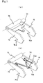
- Fig. 1 shows a basket trolley 1.
- the basket trolley 1 has a rectangular bottom panel 2.
- a fence 3 is vertically arranged in the periphery of the bottom panel 2.
- One side of the fence 3 includes double doors 3a.
- Casters 4 are set at the four corners of the bottom panel 2. Out of these, two casters are rotatable casters 4a, and the residual two casters are fixed casters 4b.
- each rotatable caster 4a includes a fork 5 in a generally U shape including a top panel 5a and side-panels 5b bent in a direction at right angles from the opposite ends thereof.
- a shaft 6 is laid across both the side-panels 5b, 5b of the fork 5 in an inserted manner, and a roller 7 is rotatably held by the shaft 6.
- a mount stand 8 is fixedly set as shown in Fig. 2 .
- the top panel 5a of the fork 5 is rotatably set at the mount stand 8 via a bearing not shown.
- the basket trolley 1 includes a brake device 10 of the rotatable caster 4a set therein.
- the brake device 10 includes a brake part 11 set at the rotatable caster 4a, an operation part 12 set at a column 3b situated diagonally with respect to the fence 3 in the embodiment shown, and a power transfer means 13 for coupling the brake part 11 and the operation part 12.
- the brake part 11 includes a frame 14.
- the frame 14 includes a tubular coupling tube 15, and levers 16 projecting in a direction at right angles from the opposite ends thereof in the embodiment illustrated in Fig. 3 .
- Each lever 16 includes a claw 16a at the tip thereof.
- the frame 14 is rotatably held by fitting the tubular coupling tube 15 to a shaft 5c set across the side-panels 5b, 5b of the fork 5.
- the frame 14 is arranged so that the levers 16 sandwich the roller 7 as shown in Fig. 3 .
- a rod 17 for hanging a spring (or a direct cable) described later thereon is set across both the levers 16.
- a plurality of projecting parts 19 are formed at disks (the opposite side-panels of the wheel) 18 on the opposite side-surfaces of the roller 7.
- the projecting parts 19 are arranged at regular intervals in the circumferential direction concentrically with the disk 18. Then, an inclined surface 19a making an acute angle with the outer circumferential surface is formed at the end of each projecting part 19.
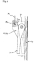
- a bracket 20 is set at the column 3b of the fence 3 as shown in Fig. 4 .
- An operation lever 21 is rotatably set at the bracket 20.
- a tongue piece 21a for holding a cable described later is protrusively provided at the base of the operation lever 21.
- the power transfer means 13 includes a cable coupling unit 22 set at the side surface of the fence 3.
- the cable coupling unit 22 includes a slide body 24 in a case 23 in the embodiment shown in Fig. 5 .
- the slide body 24 is for coupling an operation part side cable 25 and a brake part side cable 26.
- an outer tube 25a of the cable 25 is engaged with one end of the case 23, and an outer tube 26a of the cable 26 is engaged with the other end of the case 23.
- an inner cable 25b of the cable 25 is engaged with one end of the slide body 24 by a screw 27, and an inner cable 26b of the cable 26 is engaged with the other end of the slide body 24 via a spring 28.
- the slide body 24 is urged to the brake part side (downward of Fig. 5 ) by a spring 29 fitted loosely to the inner cable 25b of the cable 25.
- the cable 25 is guided upward from the operation part 12 along the column 3b, and crawls on the upper end and the side surface of the fence 3 to be guided to the cable coupling unit 22.
- the cable 26 crawls on the side surface of the fence 3 to be guided to the caster 4a, and is guided to the fork 5 through the rotation axis of the mount stand 8 as shown in Fig. 2 .
- the outer tube 26a of the cable 26 is engaged with the top panel 5a, and the inner cable 26b is rotatably coupled to the end of a spring 30 using a swivel mechanism. Then, the other end of the spring 30 is engaged with the rod 17 of the lever 16.
- the spring 30 provided at the brake part 11 is not necessarily required. It may be configured such that the inner cable 26b of the cable 26 is directly coupled to the rod 17 of the lever 16. Conversely, when the spring 30 is provided at the brake part 11, for the cable coupling unit 22, it may be configured such that the inner cable 26b of the cable 26 is directly engaged with the other end of the slide body 24 without the spring 28 interposed therebetween.
- the opposite side end of the cable 25 is engaged with the tongue piece 21a of the operation lever 21 at the operation part 12 as shown in Fig. 4 .
- the inclined surface 19a is formed at the projecting part 19, and the claw 16a of the lever 16 is caused to bite into the inclined surface 19a. Accordingly, the claw 16a is engaged with the projecting part 19 with reliability.
- the angle of the inclined surface 19a namely, the angle made between the line connecting the outer circumferential end of the projecting part 19 and the center of the roller 7 and the inclined surface is large, the engagement between the claw 16a of the lever 16 and the projecting part 19 becomes more firm.
- the angle is preferably about 30 to 50 degrees.
- the end of the inner cable 26b and the lever 16 are coupled via the stretching spring 30.
- a T-shaped flat spring 31 is disposed by being laid across the levers 16.
- a hole 32 is formed at the tip 31a, and one end of the inner cable 26b is rotatably coupled to the hole using a swivel mechanism or the like.
- a torsion coil spring 33 is disposed by being laid across the levers 16, and a hole 33a is formed at the center of the torsion coil spring 33.
- One end of the inner cable 26b is rotatably coupled with the hole 33a using a swivel mechanism, or the like.
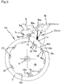
- the lever 16 is engaged with the projecting part 19 projecting toward the side of the roller 7 from above as shown in Fig. 3 .
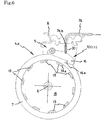
- the projecting part 19 is formed at the inner circumferential surface of the wheel 34 of the roller 7 in such a manner as to project in the direction of the shaft 6, so that the lever 16 is engaged with the projecting part 19 from below.
- the members and the parts performing the same actions as those in the embodiment are given the same reference numerals and signs in Fig. 8 , and the description thereon is omitted.
- the configuration of the cable coupling unit 22 is configured such that the inner cable 26b of the brake part side cable 26 is engaged with the other end of the slide body 24 via the spring 28.
- the spring 30 is provided at the brake part 11, as shown in Fig. 9 , for the cable coupling unit 22, it may be configured such that the inner cable 26b of the cable 26 is directly engaged, by a screw 35, with the other end of the slide body 24 without the spring 28 interposed therebetween.
- the break device for a caster in accordance with the present invention is widely applicable as a break device for a caster for use in, for example, in addition to a flat trolley except for a basket trolley, and a folding trolley, a wheelchair, a stretcher, a baby buggy, a wagon, a bed, a copying machine, an IV stand, a compressor, a spot cooler, a power generator, or a welding machine.
Landscapes
- Engineering & Computer Science (AREA)
- Mechanical Engineering (AREA)
- Chemical & Material Sciences (AREA)
- Combustion & Propulsion (AREA)
- Transportation (AREA)
- Braking Arrangements (AREA)
- Handcart (AREA)
Applications Claiming Priority (2)
| Application Number | Priority Date | Filing Date | Title |
|---|---|---|---|
| JP2019189454A JP7431010B2 (ja) | 2019-10-16 | 2019-10-16 | キャスターのブレーキ装置 |
| PCT/JP2020/020551 WO2021075079A1 (ja) | 2019-10-16 | 2020-05-25 | キャスターのブレーキ装置 |
Publications (4)
| Publication Number | Publication Date |
|---|---|
| EP3835172A1 true EP3835172A1 (de) | 2021-06-16 |
| EP3835172A4 EP3835172A4 (de) | 2022-01-12 |
| EP3835172B1 EP3835172B1 (de) | 2025-04-23 |
| EP3835172C0 EP3835172C0 (de) | 2025-04-23 |
Family
ID=75486027
Family Applications (1)
| Application Number | Title | Priority Date | Filing Date |
|---|---|---|---|
| EP20804421.4A Active EP3835172B1 (de) | 2019-10-16 | 2020-05-25 | Lenkrollenbremsvorrichtung |
Country Status (10)
| Country | Link |
|---|---|
| US (1) | US11904634B2 (de) |
| EP (1) | EP3835172B1 (de) |
| JP (1) | JP7431010B2 (de) |
| KR (1) | KR102602397B1 (de) |
| CN (1) | CN112996711A (de) |
| ES (1) | ES3031795T3 (de) |
| HU (1) | HUE071960T2 (de) |
| PL (1) | PL3835172T3 (de) |
| TW (1) | TWI865619B (de) |
| WO (1) | WO2021075079A1 (de) |
Cited By (1)
| Publication number | Priority date | Publication date | Assignee | Title |
|---|---|---|---|---|
| WO2023047135A1 (en) * | 2021-09-24 | 2023-03-30 | Armorgard Holdings Limited | Trolley |
Families Citing this family (3)
| Publication number | Priority date | Publication date | Assignee | Title |
|---|---|---|---|---|
| US12415558B1 (en) * | 2022-12-12 | 2025-09-16 | Amazon Technologies, Inc. | Containers having lever-based actuation of brakes and locks |
| JP7828115B1 (ja) * | 2025-02-20 | 2026-03-11 | 株式会社日乃本錠前 | ロック機構付きキャスター装置 |
| KR102904518B1 (ko) * | 2025-06-10 | 2025-12-26 | 주식회사 티디에스디스플레이 | 휠체어 트레드밀용 브레이크 장치 |
Family Cites Families (23)
| Publication number | Priority date | Publication date | Assignee | Title |
|---|---|---|---|---|
| DE2105547A1 (de) * | 1971-02-06 | 1972-08-10 | Tente Rollen GmbH & Co, 5678 Wermelskirchen Tente | Lenkrolle, insbesondere fur Ein kaufswagen in Selbstbedienungsladen |
| US4248445A (en) * | 1979-06-18 | 1981-02-03 | Vassar Hervey P | Caster brake and swivel lock |
| DE9412429U1 (de) * | 1994-08-02 | 1994-09-29 | Wanzl Gmbh & Co. Entwicklungs-Kg, 89340 Leipheim | Zum Befördern auf Fahrsteigen und Rolltreppen geeigneter Transportwagen |
| JPH11240305A (ja) * | 1998-02-23 | 1999-09-07 | Kawajun Kk | ブレーキ付きキャスター |
| AUPP695398A0 (en) * | 1998-11-05 | 1998-12-03 | Rubber Auto Supplies Pty. Ltd. | Brake apparatus for a shopping trolley |
| FR2850933B1 (fr) * | 2003-02-12 | 2005-04-15 | Ampafrance | Poussette a moyens de commande de blocage et du deblocage du freinage separes et places au voisinage les uns des autres |
| US6817451B1 (en) * | 2003-04-02 | 2004-11-16 | Hung-Tsun Chen | Brake system for a running stroller |
| JP5187614B2 (ja) | 2007-06-11 | 2013-04-24 | ハンマーキャスター株式会社 | キャスター |
| CA2725756A1 (en) * | 2008-06-24 | 2009-12-30 | Yazaki Kako Corporation | Brake-equipped caster |
| JP5294461B2 (ja) * | 2008-12-16 | 2013-09-18 | トーヨーベンディング株式会社 | 車輪ブレーキ機構に用いるワイヤーケーブル分岐装置 |
| JP2013049406A (ja) * | 2011-08-02 | 2013-03-14 | Hotta Kk | 自在キャスターのブレーキ機構 |
| ITFE20130006A1 (it) * | 2013-06-27 | 2014-12-28 | Sergio Toschi | Dispositivo frenante azionato manualmente per ruote a supporto girevole o fisso per carrelli da spesa e tutto quello che viene movimentato manualmente su ruote |
| EP3103653B1 (de) * | 2014-02-07 | 2019-10-09 | Nansin Co. Ltd. | Rollfuss mit doppelter verriegelung |
| JP2016199130A (ja) * | 2015-04-09 | 2016-12-01 | 株式会社日乃本錠前 | 双輪キャスターのブレーキ装置 |
| KR101573235B1 (ko) * | 2015-07-03 | 2015-12-02 | 최예진 | 사용 편의성을 향상시킨 유아용 웨건 |
| JP2017039405A (ja) * | 2015-08-20 | 2017-02-23 | 平 武次 | キャスター |
| DE102016113069A1 (de) * | 2016-07-15 | 2018-01-18 | Tente Gmbh & Co. Kg | Lenkrolle mit einem Laufrad |
| JP6854512B2 (ja) * | 2017-04-04 | 2021-04-07 | 有限会社広島ピーエス | ブレーキユニット |
| CN207045062U (zh) * | 2017-06-21 | 2018-02-27 | 中山市维唐五金制品有限公司 | 一种嵌入式刹车脚轮 |
| DE102017121146A1 (de) * | 2017-09-13 | 2019-03-14 | Tente Gmbh & Co. Kg | Formschluss-Feststelleinrichtung für eine Rolle |
| JP2020023200A (ja) * | 2018-07-30 | 2020-02-13 | 株式会社ジェネシス | 旋回自在キャスターのブレーキ装置 |
| JP7072087B2 (ja) * | 2019-01-29 | 2022-05-19 | 日立Astemo株式会社 | 電動ブレーキ装置 |
| DE102020004190A1 (de) * | 2019-08-08 | 2021-02-11 | Makita Corporation | Handwagen |
-
2019
- 2019-10-16 JP JP2019189454A patent/JP7431010B2/ja active Active
-
2020
- 2020-05-25 CN CN202080003347.5A patent/CN112996711A/zh active Pending
- 2020-05-25 KR KR1020217041474A patent/KR102602397B1/ko active Active
- 2020-05-25 HU HUE20804421A patent/HUE071960T2/hu unknown
- 2020-05-25 WO PCT/JP2020/020551 patent/WO2021075079A1/ja not_active Ceased
- 2020-05-25 US US17/055,693 patent/US11904634B2/en active Active
- 2020-05-25 ES ES20804421T patent/ES3031795T3/es active Active
- 2020-05-25 PL PL20804421.4T patent/PL3835172T3/pl unknown
- 2020-05-25 EP EP20804421.4A patent/EP3835172B1/de active Active
- 2020-09-28 TW TW109133575A patent/TWI865619B/zh active
Cited By (1)
| Publication number | Priority date | Publication date | Assignee | Title |
|---|---|---|---|---|
| WO2023047135A1 (en) * | 2021-09-24 | 2023-03-30 | Armorgard Holdings Limited | Trolley |
Also Published As
| Publication number | Publication date |
|---|---|
| US20210362545A1 (en) | 2021-11-25 |
| WO2021075079A1 (ja) | 2021-04-22 |
| PL3835172T3 (pl) | 2025-09-15 |
| JP2021062806A (ja) | 2021-04-22 |
| EP3835172B1 (de) | 2025-04-23 |
| US11904634B2 (en) | 2024-02-20 |
| JP7431010B2 (ja) | 2024-02-14 |
| HUE071960T2 (hu) | 2025-10-28 |
| KR20220010546A (ko) | 2022-01-25 |
| EP3835172C0 (de) | 2025-04-23 |
| CN112996711A (zh) | 2021-06-18 |
| TW202126503A (zh) | 2021-07-16 |
| KR102602397B1 (ko) | 2023-11-16 |
| ES3031795T3 (en) | 2025-07-11 |
| TWI865619B (zh) | 2024-12-11 |
| EP3835172A4 (de) | 2022-01-12 |
Similar Documents
| Publication | Publication Date | Title |
|---|---|---|
| EP3835172A1 (de) | Lenkrollenbremsvorrichtung | |
| US3147039A (en) | Invalid chair | |
| CN102015413B (zh) | 移动式器具的制动器作动装置 | |
| US20120066831A1 (en) | Patient transfer apparatus | |
| BR112018067644B1 (pt) | Mecanismo de elevação para conjuntos de rodas, e leito | |
| CN103110481A (zh) | 一种病人转运床及其底盘装置 | |
| JP2020023200A (ja) | 旋回自在キャスターのブレーキ装置 | |
| NO812374L (no) | Nettseng. | |
| CN108209917B (zh) | 台臂板调整组件 | |
| JP2010143290A (ja) | 車輪ブレーキ機構に用いるワイヤーケーブル分岐装置 | |
| CN106691715B (zh) | 一种医用过床车 | |
| JP6616577B2 (ja) | ブレーキ機構およびこれを備える移動式テーブル | |
| JP6202519B2 (ja) | ロック付きキャスターならびに該キャスターを適用した歩行器及び椅子 | |
| EP2895127A1 (de) | Führungsrad für ein krankenhausbett | |
| JP5650827B1 (ja) | スライドレール及びそれを用いた玄関収納家具 | |
| JP5778573B2 (ja) | ストレッチャー | |
| JP2015213723A (ja) | 車椅子 | |
| CN220495188U (zh) | 一种病历车 | |
| JP2006109877A (ja) | 歩行器 | |
| KR200363567Y1 (ko) | 캐스터용 제동장치 | |
| JP4978358B2 (ja) | 蓋リフター | |
| CN111067628B (zh) | 支撑装置及底座 | |
| CN210542105U (zh) | 一种便于转移病人的手术推车 | |
| JP4340816B2 (ja) | 車椅子 | |
| JP2019123487A (ja) | 自在キャスターのブレーキ機構 |
Legal Events
| Date | Code | Title | Description |
|---|---|---|---|
| STAA | Information on the status of an ep patent application or granted ep patent |
Free format text: STATUS: UNKNOWN |
|
| STAA | Information on the status of an ep patent application or granted ep patent |
Free format text: STATUS: THE INTERNATIONAL PUBLICATION HAS BEEN MADE |
|
| PUAI | Public reference made under article 153(3) epc to a published international application that has entered the european phase |
Free format text: ORIGINAL CODE: 0009012 |
|
| STAA | Information on the status of an ep patent application or granted ep patent |
Free format text: STATUS: REQUEST FOR EXAMINATION WAS MADE |
|
| 17P | Request for examination filed |
Effective date: 20201209 |
|
| AK | Designated contracting states |
Kind code of ref document: A1 Designated state(s): AL AT BE BG CH CY CZ DE DK EE ES FI FR GB GR HR HU IE IS IT LI LT LU LV MC MK MT NL NO PL PT RO RS SE SI SK SM TR |
|
| A4 | Supplementary search report drawn up and despatched |
Effective date: 20211215 |
|
| RIC1 | Information provided on ipc code assigned before grant |
Ipc: B60B 33/00 20060101ALI20211209BHEP Ipc: B62B 5/04 20060101AFI20211209BHEP |
|
| STAA | Information on the status of an ep patent application or granted ep patent |
Free format text: STATUS: EXAMINATION IS IN PROGRESS |
|
| 17Q | First examination report despatched |
Effective date: 20221004 |
|
| DAV | Request for validation of the european patent (deleted) | ||
| DAX | Request for extension of the european patent (deleted) | ||
| GRAP | Despatch of communication of intention to grant a patent |
Free format text: ORIGINAL CODE: EPIDOSNIGR1 |
|
| STAA | Information on the status of an ep patent application or granted ep patent |
Free format text: STATUS: GRANT OF PATENT IS INTENDED |
|
| INTG | Intention to grant announced |
Effective date: 20241122 |
|
| GRAS | Grant fee paid |
Free format text: ORIGINAL CODE: EPIDOSNIGR3 |
|
| GRAA | (expected) grant |
Free format text: ORIGINAL CODE: 0009210 |
|
| STAA | Information on the status of an ep patent application or granted ep patent |
Free format text: STATUS: THE PATENT HAS BEEN GRANTED |
|
| AK | Designated contracting states |
Kind code of ref document: B1 Designated state(s): AL AT BE BG CH CY CZ DE DK EE ES FI FR GB GR HR HU IE IS IT LI LT LU LV MC MK MT NL NO PL PT RO RS SE SI SK SM TR |
|
| REG | Reference to a national code |
Ref country code: GB Ref legal event code: FG4D |
|
| REG | Reference to a national code |
Ref country code: CH Ref legal event code: EP |
|
| REG | Reference to a national code |
Ref country code: DE Ref legal event code: R096 Ref document number: 602020050050 Country of ref document: DE |
|
| REG | Reference to a national code |
Ref country code: IE Ref legal event code: FG4D |
|
| U01 | Request for unitary effect filed |
Effective date: 20250506 |
|
| U07 | Unitary effect registered |
Designated state(s): AT BE BG DE DK EE FI FR IT LT LU LV MT NL PT RO SE SI Effective date: 20250512 |
|
| REG | Reference to a national code |
Ref country code: ES Ref legal event code: FG2A Ref document number: 3031795 Country of ref document: ES Kind code of ref document: T3 Effective date: 20250711 |
|
| PGFP | Annual fee paid to national office [announced via postgrant information from national office to epo] |
Ref country code: HU Payment date: 20250722 Year of fee payment: 6 |
|
| U20 | Renewal fee for the european patent with unitary effect paid |
Year of fee payment: 6 Effective date: 20250715 |
|
| PGFP | Annual fee paid to national office [announced via postgrant information from national office to epo] |
Ref country code: ES Payment date: 20250704 Year of fee payment: 6 |
|
| PG25 | Lapsed in a contracting state [announced via postgrant information from national office to epo] |
Ref country code: NO Free format text: LAPSE BECAUSE OF FAILURE TO SUBMIT A TRANSLATION OF THE DESCRIPTION OR TO PAY THE FEE WITHIN THE PRESCRIBED TIME-LIMIT Effective date: 20250723 Ref country code: GR Free format text: LAPSE BECAUSE OF FAILURE TO SUBMIT A TRANSLATION OF THE DESCRIPTION OR TO PAY THE FEE WITHIN THE PRESCRIBED TIME-LIMIT Effective date: 20250724 |
|
| PGFP | Annual fee paid to national office [announced via postgrant information from national office to epo] |
Ref country code: TR Payment date: 20250718 Year of fee payment: 6 Ref country code: PL Payment date: 20250616 Year of fee payment: 6 |
|
| PG25 | Lapsed in a contracting state [announced via postgrant information from national office to epo] |
Ref country code: HR Free format text: LAPSE BECAUSE OF FAILURE TO SUBMIT A TRANSLATION OF THE DESCRIPTION OR TO PAY THE FEE WITHIN THE PRESCRIBED TIME-LIMIT Effective date: 20250423 |
|
| PGFP | Annual fee paid to national office [announced via postgrant information from national office to epo] |
Ref country code: CH Payment date: 20250701 Year of fee payment: 6 |
|
| PG25 | Lapsed in a contracting state [announced via postgrant information from national office to epo] |
Ref country code: RS Free format text: LAPSE BECAUSE OF FAILURE TO SUBMIT A TRANSLATION OF THE DESCRIPTION OR TO PAY THE FEE WITHIN THE PRESCRIBED TIME-LIMIT Effective date: 20250723 |
|
| PGFP | Annual fee paid to national office [announced via postgrant information from national office to epo] |
Ref country code: CZ Payment date: 20250612 Year of fee payment: 6 |
|
| PG25 | Lapsed in a contracting state [announced via postgrant information from national office to epo] |
Ref country code: IS Free format text: LAPSE BECAUSE OF FAILURE TO SUBMIT A TRANSLATION OF THE DESCRIPTION OR TO PAY THE FEE WITHIN THE PRESCRIBED TIME-LIMIT Effective date: 20250823 |
|
| REG | Reference to a national code |
Ref country code: HU Ref legal event code: AG4A Ref document number: E071960 Country of ref document: HU |
|
| PG25 | Lapsed in a contracting state [announced via postgrant information from national office to epo] |
Ref country code: SM Free format text: LAPSE BECAUSE OF FAILURE TO SUBMIT A TRANSLATION OF THE DESCRIPTION OR TO PAY THE FEE WITHIN THE PRESCRIBED TIME-LIMIT Effective date: 20250423 |
|
| PG25 | Lapsed in a contracting state [announced via postgrant information from national office to epo] |
Ref country code: SK Free format text: LAPSE BECAUSE OF FAILURE TO SUBMIT A TRANSLATION OF THE DESCRIPTION OR TO PAY THE FEE WITHIN THE PRESCRIBED TIME-LIMIT Effective date: 20250423 |
|
| PG25 | Lapsed in a contracting state [announced via postgrant information from national office to epo] |
Ref country code: MC Free format text: LAPSE BECAUSE OF FAILURE TO SUBMIT A TRANSLATION OF THE DESCRIPTION OR TO PAY THE FEE WITHIN THE PRESCRIBED TIME-LIMIT Effective date: 20250423 |
|
| PLBE | No opposition filed within time limit |
Free format text: ORIGINAL CODE: 0009261 |
|
| STAA | Information on the status of an ep patent application or granted ep patent |
Free format text: STATUS: NO OPPOSITION FILED WITHIN TIME LIMIT |
|
| REG | Reference to a national code |
Ref country code: CH Ref legal event code: L10 Free format text: ST27 STATUS EVENT CODE: U-0-0-L10-L00 (AS PROVIDED BY THE NATIONAL OFFICE) Effective date: 20260304 |
|
| 26N | No opposition filed |
Effective date: 20260126 |
|
| PGFP | Annual fee paid to national office [announced via postgrant information from national office to epo] |
Ref country code: GB Payment date: 20260327 Year of fee payment: 7 |
|
| PG25 | Lapsed in a contracting state [announced via postgrant information from national office to epo] |
Ref country code: IE Free format text: LAPSE BECAUSE OF NON-PAYMENT OF DUE FEES Effective date: 20250525 |