EP3835501A1 - Arrangement pour connecter une pièce de construction avec une partie extérieure frontale - Google Patents
Arrangement pour connecter une pièce de construction avec une partie extérieure frontale Download PDFInfo
- Publication number
- EP3835501A1 EP3835501A1 EP20206149.5A EP20206149A EP3835501A1 EP 3835501 A1 EP3835501 A1 EP 3835501A1 EP 20206149 A EP20206149 A EP 20206149A EP 3835501 A1 EP3835501 A1 EP 3835501A1
- Authority
- EP
- European Patent Office
- Prior art keywords
- outer part
- force introduction
- profile
- introduction element
- building
- Prior art date
- Legal status (The legal status is an assumption and is not a legal conclusion. Google has not performed a legal analysis and makes no representation as to the accuracy of the status listed.)
- Granted
Links
Images




Classifications
-
- E—FIXED CONSTRUCTIONS
- E04—BUILDING
- E04B—GENERAL BUILDING CONSTRUCTIONS; WALLS, e.g. PARTITIONS; ROOFS; FLOORS; CEILINGS; INSULATION OR OTHER PROTECTION OF BUILDINGS
- E04B1/00—Constructions in general; Structures which are not restricted either to walls, e.g. partitions, or floors or ceilings or roofs
- E04B1/003—Balconies; Decks
- E04B1/0038—Anchoring devices specially adapted therefor with means for preventing cold bridging
Definitions
- the present invention relates to an arrangement for connecting a structural part to an outer part positioned in front of the structural part.
- Connection elements which have been known for a long time, therefore generally have connection elements for power transmission to a structural part as well as a body made of insulating material, which brings about the greatest possible thermal insulation of the upstream outer part.
- a cantilever plate connection element with an elongated, cuboidal insulating body made of thermally insulating material.
- the insulating body is interspersed with elongated, metal reinforcement elements, which extend essentially transversely to the insulating body and which are designed to absorb tensile forces.
- the cantilever plate connection element has shear force bars made of reinforcing steel and steel construction parts that act as pressure elements.
- the component has an insulating body as well as tensile, compressive and possibly transverse force elements.
- the shear force element of the DE 101 30 866 A1 is formed by two intersecting, mirror-inverted bars.
- connection elements that can be used with a high degree of flexibility in the event of differing structural requirements. These could be produced cheaply in larger numbers and kept in stock.
- the present invention is based on the object of providing a connection element which, with good static load capacity and good thermal insulation, can be used with high flexibility for the connection of the most varied of variants of external parts and structural parts. According to the invention, this object is achieved by the arrangement for connecting a structural part to an outer part located in front of the structural part, according to independent patent claim 1. Further advantageous aspects, details and configurations of the invention emerge from the dependent claims, the description and the drawings.
- the arrangement according to the invention for connecting a structural part to an outer part in front of the structural part comprises at least one structural part-side force introduction element arranged in the structural part, the building-part-side force introduction element having an end face on its side facing away from the building part in the installed state, the front face of the building-part-side force introduction element flush with the building part with the outer side of the structural part facing the outer part.
- the arrangement also comprises at least one outer part-side force introduction element arranged in the outer part, the outer-part-side force introduction element having an end face on its side facing away from the outer part in the installed state, the end face of the outer part Force introduction element in the installed state is flush with the outer side of the outer part facing the structural part.
- At least one insulating body arranged between the structural part and the upstream outer part in the installed state and at least one connecting element penetrating the insulating body in the installed state are provided.
- the connecting element is firmly connected to the force introduction element on the building part and firmly to the force introduction element on the outer part, the connecting element penetrating the force introduction element on the building part and / or the force introduction element on the outer part in the installed state.
- the connecting element has an external thread in its section protruding into the outer part and / or into the structure, with at least one threaded nut being screwed onto the external thread arranged in the outer part and / or the structure protruding into the connecting element section in the installed state.
- the arrangement also comprises at least one cylindrical sleeve which supports itself on the end face of the force introduction element on the outer part side and on the end face of the force introduction element on the building part side and encompasses the connecting element, the sleeve in the installed state after the at least one threaded nut has been fastened with a predetermined tightening torque between the end face of the outer part Force introduction element and the end face of the building part-side force introduction element is clamped.
- the cylindrical sleeve provided in the arrangement according to the invention engages around the connecting element which is firmly connected to a force introduction element.
- this connecting element penetrates at least one of the two force introduction elements, that is to say either the force introduction element on the building part or the force introduction element on the outer part.
- a threaded nut is screwed onto an external thread provided in the section of the connecting element protruding into the outer part or into the structural part. This screwing of the threaded nut takes place with a predetermined tightening torque, whereby the sleeve is clamped between the end face of the force introduction element on the outer part and the end face of the force introduction element on the building part.
- the sleeve then forms a non-slip connection between the structural part and the outer part, by means of which transverse forces can be transmitted.
- the arrangement according to the invention for connecting a structural part to an outer part positioned in front of the structural part thus provides a universal connection with whose help a cantilevered element can be connected to a structure regardless of the specific design of the outer part and regardless of the specific design of the structural part.
- the requirements of good static load capacity and good thermal insulation are met by the arrangement according to the invention.
- Particularly noteworthy, however, is the great flexibility with which the arrangement can be used in a wide variety of installation situations. Only two contact surfaces are absolutely necessary, on which the sleeve can be supported on the structural part on the one hand and on the outer part on the other hand. Otherwise, the arrangement can be used in connection with any type of steel outer part, reinforced concrete outer part, steel structure part and reinforced concrete structure. In any case, the sleeve forms a non-slip connection between the structural part and the outer part, by means of which transverse forces and compressive forces can be transmitted.
- the structural part-side force introduction element is firmly connected to at least one reinforcement element for absorbing tensile or compressive forces, the at least one reinforcement element protruding into the structural element for absorbing tensile or compressive forces.
- this represents the simplest, safest and most permanent fastening option for the structural part-side force transmission element.
- the structural part-side force introduction element in the case of the connection of an outer part to a steel structure part is either designed as an end plate welded to the steel structure part or the building part-side force introduction element represents an integral part of the steel structure of the steel structure part.
- a reinforced concrete outer part is connected to a structural part
- the force introduction element on the outer part is firmly connected to at least one reinforcement element for absorbing tensile or compressive forces, the at least one reinforcement element protruding into the outer part for absorbing tensile or compressive forces.
- this represents the simplest, safest and most permanent fastening option for the force introduction element on the outer part.
- the external part-side force introduction element in the case of the connection of a steel outer part to a structural part is either designed as a face plate welded to the steel outer part or the external part-side force introduction element represents an integral part of the steel structure of the steel outer part.
- the structural part-side force introduction element is a structural-part-side U-profile consisting of steel plates, the U-profile having an end plate forming the web of the U-profile and at least two, the legs having steel plates forming the U-profile.
- Reinforcement elements are provided for absorbing tensile and compressive forces, which are firmly connected to the U-profile, in particular welded, and which protrude into the structural part.
- the end plate of the U-profile ends flush with the outer side of the structural part facing the outer part and thus forms the end face of the structural part-side force introduction element.
- At least one opening is provided in the end plate, the connecting element penetrating the opening in the installed state.
- the connecting element has an external thread at least in its section protruding into the structural part, with a threaded nut being screwed onto the external thread arranged in the structural part protruding into the structural part of the connecting element.
- the reinforcing elements protruding into the structural part for absorbing tensile and compressive forces are firmly connected to the steel plates forming the legs of the U-profile, in particular to the outside of the steel plates forming the legs of the U-profile.
- the space present in the interior of the U-profile thus remains freely accessible, which is why the screwing of the threaded nuts can be carried out in a particularly simple manner.
- the opening provided in the end plate of the U-profile on the building part is preferably an elongated hole, the elongated hole preferably extending in the direction of its longitudinal axis from 20 mm to 60 mm, particularly preferably from 25 mm to 50 mm, particularly preferably from 30 mm mm to 40 mm.
- the connecting elements generally have a cross-sectional diameter of 8 mm to 16 mm.
- a reinforced concrete outer part is connected to a structural part, according to a preferred embodiment it is the force introduction element on the outer part around an outer part-side U-profile consisting of steel plates, the U-profile having an end plate forming the web of the U-profile and at least two steel plates forming the legs of the U-profile.
- Reinforcement elements that are fixedly connected to the U-profile, in particular welded, are provided for absorbing tensile and compressive forces which protrude into the outer part.
- the end plate ends flush with the outer side of the outer part facing the structural part and thus forms the end face of the force introduction element on the outer part.
- At least one opening is provided in the end plate, the connecting element penetrating the opening in the installed state.
- the connecting element has an external thread at least in its section protruding into the outer part, wherein in the installed state a threaded nut is screwed onto the section of the connecting element that protrudes into the outer part.
- the reinforcing elements protruding into the outer part to absorb tensile and compressive forces are firmly connected to the steel plates forming the legs of the U-profile, particularly preferably to the outside of the steel plates forming the legs of the U-profile.
- the space present in the interior of the U-profile remains freely accessible, which is why the screw nuts can be screwed together in a particularly simple manner.
- the opening provided in the end plate of the outer part-side U-profile is preferably an elongated hole, the elongated hole preferably extending in the direction of its longitudinal axis from 20 mm to 60 mm, particularly preferably from 25 mm to 50 mm, particularly preferably from 30 mm mm to 40 mm.
- the connecting elements generally have a cross-sectional diameter of 8 mm to 16 mm.
- the building part side and / or the force introduction element on the outside part is firmly connected to at least one reinforcement element for absorbing tensile or compressive forces.
- This fixed connection can in principle be implemented in any way.
- the force introduction element is preferably welded directly to the reinforcement element.
- the force introduction element on the outer part or the force introduction element on the building part is a threaded sleeve, the threaded sleeve being screwed to the connecting element in the installed state.
- the threaded sleeve is preferably welded to the reinforcement element, the thread axis coinciding with the longitudinal axis of the reinforcement element, which is generally designed as a reinforcing rod.
- the threaded sleeve provides an internal thread into which the connecting element is subsequently screwed with its external thread, which is required in this case.
- the present invention is not limited to threaded sockets or to the above-described U-profiles as force introduction elements.
- the force introduction element on the outside part or the force introduction element on the building part is preferably a steel girder, particularly preferably an I-steel girder, the steel girder having an end plate.
- the side of the end plate facing away from the steel beam forms the end face of the force introduction element.
- the connecting element is preferably a threaded bolt.
- the connecting element has an external thread in its section protruding into the outer part and / or into its section projecting into the structural part, which is used for the subsequent fastening of a threaded nut.
- a threaded bolt continuously provided with an external thread is the most cost-effective way of realizing this property.
- the connecting element can be displaced perpendicular to the end face of the force introduction elements without having to pay attention to a central section of the connecting element that does not have an external thread.
- the sleeve is a steel sleeve, preferably a stainless steel sleeve.
- a correspondingly thick-walled cylindrical stainless steel sleeve ideally provides all the properties desired for the sleeve provided according to the invention.
- a steel sleeve, in particular a stainless steel sleeve is inexpensive to manufacture, easily available and has the strength required to transmit transverse forces.
- the sleeve can easily be threaded onto a connecting element and, in particular, onto a threaded bolt.
- a sleeve made of stainless steel also has the known advantages with regard to resistance to rust.
- the cylindrical sleeve preferably has an inner diameter between 20 mm and 30 mm, particularly preferably between 22 mm and 26 mm, and particularly preferably an inner diameter of 23 mm.
- the outer diameter of the cylindrical sleeve is preferably between 40 mm and 60 mm, particularly preferably between 45 mm and 55 mm, and particularly preferably 50 mm.
- the arrangement according to the invention comprises at least one connecting element and correspondingly at least one cylindrical sleeve encompassing this connecting element.
- the connecting element is firmly connected to the force introduction elements, the force introduction element, according to a preferred embodiment, in turn being connected to a reinforcement element for absorbing tensile or compressive forces.
- the at least one connecting element is thus connected in the installed state to at least one reinforcement element for absorbing tensile or compressive forces. Whether this reinforcement element is a reinforcement element for absorbing tensile forces or a reinforcement element for absorbing compressive forces depends on the specific load situation.
- the outer part is a freely cantilevered balcony in which tension is transmitted in the upper reinforcement layer and pressure in the lower reinforcement layer
- the connecting element and sleeve should be provided in the compression level, since the defined prestressing force would be reduced by the tensile load in the tension level .
- transverse forces in the tension plane would only be transmitted to a very limited extent via a non-slip connection.
- a static system is included to which mainly transverse forces have to be transmitted.
- At least two connecting elements and at least two sleeves are provided.
- the static requirements associated with a specific installation situation can be met not only by correspondingly adapting the number of arrangements according to the present invention, but also by adapting the number of connecting elements per arrangement.
- the variable dimensioning of the outer part can make it necessary to adapt the number of arrangements according to the present invention and the number of connecting elements per arrangement.
- elongated holes are provided both in the face plate of the outer part-side U-profile and in the face plate of the structural-part-side U-profile.
- the longitudinal axes of these elongated holes are preferably arranged at an angle of 90 ° relative to one another in the two end plates.
- the adjustment process is particularly simple if the longitudinal axis of the elongated hole provided in the end plate of the outer part-side U-profile is oriented in the horizontal direction in the installed state and at the same time the longitudinal axis of the elongated hole provided in the end plate of the building-part-side U-profile in the installed state in the vertical direction is oriented or if the longitudinal axis of the elongated hole provided in the end plate of the outer part-side U-profile is oriented in the vertical direction in the installed state and at the same time the longitudinal axis of the elongated hole provided in the end plate of the building-part-side U-profile is oriented in the installed state in the horizontal direction. Due to the vertical or horizontal orientation of the elongated holes, the adjustment can be carried out intuitively by moving the outer part in the corresponding directions.
- a prefabricated balcony is equipped with, for example, six external steel installation parts with U-profiles, the end plates of which are all flush with the outside of the balcony, which, when installed, faces the structural part.
- the prefabricated balcony is to be connected
- the prefabricated balcony When assembling the prefabricated balcony, it is first placed in its approximate position relative to the ceiling / floor slab. Due to the elongated holes in the end plates of steel built-in parts on the outside and steel built-in parts on the building part, the connecting elements can be passed through the end plates without any problems. After the connecting elements have been placed, the threaded nuts are provisionally tightened on the section of the connecting element protruding into the structural part and on the section of the connecting element protruding into the outer part. This screwing is also possible without any problems because during the concreting process of the ceiling / floor slab as well as during the production of the prefabricated balcony, the interior space formed by the respective end plate and the two steel plates forming the legs of the U-profile is kept free of concrete by means of appropriate placeholders. After removing the placeholders, this space is available for screwing the threaded nuts.
- the structural part is a ceiling / floor slab and the outer part is a prefabricated balcony, the treads provided in the finished state should be at the same height level. Any possible offset in the vertical direction can easily be compensated for due to the elongated holes.
- the position of the prefabricated balcony can also be readjusted in the horizontal direction and, to a certain extent, the balcony can also be tilted, since the dimensioning of the elongated holes both in the direction of their longitudinal axis and in the direction of the transverse axis of the elongated holes, which is oriented perpendicular to the longitudinal axis in the plane of the end plate Exceeds the diameter of the fasteners.
- the connecting elements guided through the elongated holes therefore have a certain amount of play in each direction in the plane of the end plates, which enables the complete prefabricated balcony to be tilted slightly.
- the threaded nuts are tightened with a previously determined, defined tightening torque.
- the sleeve is pretensioned between the two end faces of the force introduction elements arranged opposite one another in the joint. Occurring transverse forces can therefore be transmitted through friction of the sleeve on the end faces in the joint.
- Reinforcing elements protruding into the outer part are preferably provided for absorbing transverse forces, these reinforcing elements particularly preferably being fixed to the face opposite the end face of the force introduction element on the outer part or with the inside of the end plate facing the outer part or with the legs of the U-profile forming steel plates, in particular with the outside of the steel plates forming the legs of the U-profile, are connected.
- reinforcement elements protruding into the structural part are provided for absorbing transverse forces, these reinforcing elements for absorbing transverse forces preferably with the surface opposite the end face of the force introduction element on the structural part or with the inside of the front plate facing the structural part or with the legs of the U-profile forming steel plates, in particular with the outside of the steel plates forming the legs of the U-profile, are connected.
- the transverse forces transmitted by the sleeve can be introduced directly into the reinforcement elements opposite the end face or face plate in order to absorb transverse forces.
- a particularly advantageous introduction of the transverse forces into the outer part is possible if the reinforcement elements protruding into the outer part wrap around a threaded sleeve to absorb the transverse forces.
- a particularly advantageous introduction of the transverse forces into the structural part is possible if the reinforcement elements protruding into the structural part each wrap around a threaded sleeve to absorb the transverse forces.
- the Figure 1 shows a schematic representation of a vertical section through an arrangement for connecting a reinforced concrete structural part B to an outer part A located in front of the reinforced concrete structural part B.
- the arrangement comprises four force introduction elements K arranged in the structural part B.
- the force introduction elements are threaded sleeves 6, one of which is in the Figure 6 is shown as an example.
- Each of the threaded sockets 6 is firmly welded to a reinforcement element B3Z, B3D for absorbing tensile or compressive forces.
- the threaded sleeve 6 has an end face KS on its side facing away from structural part B in the installed state (see Figure 6 ), with the front face KS of the threaded sleeve 6 in the installed state flush with the outside of the structural part B facing the outer part A (see Figure 1 ).
- the reinforcement elements B3Z, B3D for absorbing tensile or compressive forces protrude into structural part B.
- a reinforcement element B3Q is provided for absorbing transverse forces, which reinforcement element wraps around a threaded sleeve and projects into structural part B in the illustrated embodiment.
- the arrangement also comprises an outer part-side steel built-in part A1 arranged in the outer part A, the outer part-side steel built-in part A1 having a face plate A2S and reinforcement elements A3Z, A3D, A3Q for absorbing tensile, compressive and transverse forces, the face plate A2S im installed state is flush with the outside of the outer part A facing the structural part B and the reinforcement elements A3Z, A3D, A3Q protrude into the outer part A to absorb tensile, compressive and transverse forces.
- the insulating body 4 which is arranged in the installed state between the structural part B and the upstream outer part A, is in the Figure 1 Not shown.
- the arrangement of the insulating body 4 can be according to the analogous representation of an alternative embodiment Figure 4 can be removed.
- connection elements 5 penetrating the insulating body 4 in the installed state
- the connecting elements 5 being designed in the form of threaded bolts.
- Each of the threaded bolts penetrates an elongated hole AL provided in the end plate A2S of the U-profile A2 of the steel built-in part A1 on the outer part (see also Figure 5 ).
- the connecting elements 5 are firmly connected to a force introduction element K in each case in the installed state.
- the threaded bolts 5 are screwed to the threaded sleeves 6. Since the threaded sockets 6 are permanently welded to a reinforcement element B3Z, B3D to absorb tensile or compressive forces, the threaded bolts 5 are also firmly connected to the reinforcement elements B3Z, B3D to absorb tensile or compressive forces when installed.
- the threaded bolts 5 have a continuous external thread and thus also in their sections protruding into the outer part A. In the installed state, a threaded nut is screwed onto each of these sections.
- the threaded nuts are in the Figure 1 not shown.
- Threaded sleeve shown in detail. In the exemplary embodiment shown, it is a cylindrical stainless steel sleeve with an internal diameter Ri of 23 mm and an external diameter Ra of 50 mm. In the Figure 1 only one of the stainless steel sleeves 7 is shown. The stainless steel sleeve 7 is supported on the face plate A2S of the outer part Steel built-in part A1 and on the end face KS of the threaded sleeve 6 arranged in the structural part B.
- the stainless steel sleeve 7 lies between the end plate A2S of the external steel installation part A1 and the end face KS of the in the structural part B arranged threaded sleeve 6 clamped before.
- the sleeve 7 then forms a non-slip connection between structural part B and outer part A, by means of which transverse forces can be transmitted.
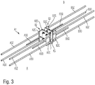
- FIGS. 3 and 4th show schematically in perspective representation ( Figure 3 ) and in the horizontal section ( Figure 4 ) Another embodiment of an arrangement for connecting a structural part B to an outer part A upstream of the structural part B.
- structural part B is a ceiling / floor slab of a building
- outer part A is a subsequent one prefabricated balcony to be connected to the building.
- the arrangement comprises a force introduction element which is arranged in the top / bottom plate B and, in the embodiment shown, is designed in the form of a U-profile B2 consisting of steel plates.
- the end plate B2S which forms the web of the U-profile B2, ends flush with the outside of the ceiling / floor plate B facing the prefabricated balcony A and thus forms the end face KS of the force introduction element K.
- the two steel plates B2C forming the legs of the U-profile protrude into the ceiling / floor plate B.
- Reinforcement elements B3Z, B3D, B3Q are welded to the U-profile B2 to absorb tensile, compressive and transverse forces.
- the tension rods B3Z and the compression rods B3D are attached on the outside to the steel plates B2C that form the legs of the U-profile.
- the transverse force elements B3Q are attached to the inside of the face plate B2S facing the top / bottom plate B.
- Four elongated holes BL are provided in the end plate B2S, the longitudinal axis of which (see Figure 5 ) runs in the vertical direction when installed.
- the arrangement also comprises a built-in steel part A1 on the outside, which is arranged in the prefabricated balcony and which comprises a U-profile A2 consisting of steel plates.
- the face plate A2S which forms the web of the U-profile A2, ends flush with the outside of the prefabricated balcony A facing the ceiling / floor plate B when installed.
- the two steel plates A2C which form the legs of the U-profile, protrude into the prefabricated balcony A.
- Reinforcement elements A3Z, A3D, A3Q are welded to U-profile A2 to absorb tensile, compressive and transverse forces.
- the tension rods A3Z and the compression rods A3D are attached on the outside to the steel plates A2C that form the legs of the U-profile.
- the transverse force elements A3Q are attached to the inside of the end plate A2S facing the prefabricated balcony A.
- Four elongated holes AL are provided in the end plate A2S, the longitudinal axis of which runs in the horizontal direction when installed.
- the longitudinal axis L of the elongated holes BL provided in the end plate B2S of the U-profile B2 arranged in the ceiling / floor plate B and the elongated holes AL provided in the end plate A2S of the U-profile A2 of the steel built-in part A1 on the outside are for clarification When installed, they are arranged at an angle of around 90 ° to each other.
- the elongated holes in the face plate B2S of the U-profile B2 arranged in the top / bottom plate B are arranged in such a way that their longitudinal axis runs in the vertical direction when installed.
- the elongated holes in the end plate A2S of the U-profile A2 of the steel built-in part A1 arranged on the outside of the prefabricated balcony A are each arranged so that their longitudinal axis runs in the horizontal direction when installed.
- the described orientation of the elongated holes AL, BL makes it possible to adjust the position of the prefabricated balcony during installation on the building both in the vertical direction and in the horizontal direction.
- an insulating body 4 is arranged between the structural part B and the upstream outer part A, by means of which an improved thermal insulation of the building is achieved.
- the arrangement includes in the Figures 3 and 4th
- the embodiment shown also includes four threaded bolts 5, each of which forms a connecting element 5 which penetrates the insulating body 4 in the installed state.
- each of the threaded bolts penetrates both the elongated hole BL provided in the end plate B2S of the U-profile B2 and the elongated hole AL provided in the end plate A2S of the U-profile A2 of the steel insert A1 on the outside.
- the threaded bolts 5 have an external thread over their entire extent, that is to say also in their sections protruding into the structural part B and in their sections protruding into the outer part A. In the installed state, threaded nuts are screwed onto the sections of the threaded bolts 5 protruding into the structural part B or onto the sections of the threaded bolts 5 protruding into the outer part A.
- the stainless steel sleeve 7 After fastening the threaded nuts by screwing them onto the external thread of the threaded bolt 5 in the sections penetrating the respective end plates A2S, B2S with a predetermined tightening torque, the stainless steel sleeve 7 is clamped between the end plates A2S, B2S. The stainless steel sleeve 7 then forms a non-slip connection between structural part B and outer part A, by means of which transverse forces can be transmitted.
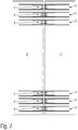
- the Figure 7 shows a schematic representation of a horizontal section through a ceiling / floor slab B of a building and a prefabricated balcony A connected to the ceiling / floor slab.
- the prefabricated balcony A is equipped with six external steel built-in parts A1.
- six force introduction elements K are concreted in the ceiling / floor slab B.
- there are six force introduction elements K each designed in the form of a U-profile consisting of steel plates, as they are in connection with the Figures 3 and 4th have been explained.
- the interior space formed by the respective end plate and the two steel plates forming the legs of the U-profile is kept free of concrete by means of appropriate placeholders. After removing the placeholders, this space is available for screwing the threaded nuts.
- the interiors of the U-profiles are potted with concrete or a resin or another suitable filling material or covered with a suitable cover.
Landscapes
- Engineering & Computer Science (AREA)
- Architecture (AREA)
- Physics & Mathematics (AREA)
- Electromagnetism (AREA)
- Civil Engineering (AREA)
- Structural Engineering (AREA)
- Joining Of Building Structures In Genera (AREA)
Applications Claiming Priority (1)
| Application Number | Priority Date | Filing Date | Title |
|---|---|---|---|
| DE102019133997.9A DE102019133997A1 (de) | 2019-12-11 | 2019-12-11 | Anordnung zum Verbinden eines Bauwerkteils mit einem dem Bauwerkteil vorgelagerten Außenteil |
Publications (2)
| Publication Number | Publication Date |
|---|---|
| EP3835501A1 true EP3835501A1 (fr) | 2021-06-16 |
| EP3835501B1 EP3835501B1 (fr) | 2024-01-10 |
Family
ID=73172519
Family Applications (1)
| Application Number | Title | Priority Date | Filing Date |
|---|---|---|---|
| EP20206149.5A Active EP3835501B1 (fr) | 2019-12-11 | 2020-11-06 | Arrangement pour connecter une pièce de construction avec une partie extérieure frontale |
Country Status (2)
| Country | Link |
|---|---|
| EP (1) | EP3835501B1 (fr) |
| DE (1) | DE102019133997A1 (fr) |
Citations (6)
| Publication number | Priority date | Publication date | Assignee | Title |
|---|---|---|---|---|
| DE3005571B1 (de) | 1980-02-14 | 1981-06-04 | Eberhard 7570 Baden-Baden Schöck | Bauelement zur Waermedaemmung bei Gebaeuden |
| DE19908388A1 (de) | 1999-02-26 | 2000-08-31 | Schoeck Bauteile Gmbh | Bauelement zur Wärmedämmung |
| DE10130866A1 (de) | 2001-06-22 | 2003-01-02 | Schoeck Entwicklungsgmbh | Bauelement zur Wärmedämmung |
| WO2005035892A1 (fr) * | 2003-10-10 | 2005-04-21 | Hitek Construction Ag | Dispositif comprenant une barre en plastique renforce par des fibres et servant a transmettre une charge a travers une couche calorifuge |
| WO2015024556A1 (fr) * | 2013-08-21 | 2015-02-26 | Heiko Schmidt | Procédé pour assembler des pièces et module correspondant |
| WO2018163062A1 (fr) * | 2017-03-07 | 2018-09-13 | Svein Berg Holding As | Dispositif de fixation et procédé de montage d'une pièce en porte-à-faux sur un bâtiment |
Family Cites Families (3)
| Publication number | Priority date | Publication date | Assignee | Title |
|---|---|---|---|---|
| GB1524252A (en) * | 1975-05-13 | 1978-09-06 | Ccl Systems Ltd | Joining concrete members in buildings |
| DE3933594A1 (de) * | 1989-10-07 | 1991-04-11 | Hilary Weinberg | Balkon |
| DE102012013489A1 (de) * | 2012-07-09 | 2014-05-08 | Schöck Bauteile GmbH | Vorrichtung zum schwingungsentkoppelten Auflagern eines auskragenden Gebäudeteils |
-
2019
- 2019-12-11 DE DE102019133997.9A patent/DE102019133997A1/de not_active Withdrawn
-
2020
- 2020-11-06 EP EP20206149.5A patent/EP3835501B1/fr active Active
Patent Citations (6)
| Publication number | Priority date | Publication date | Assignee | Title |
|---|---|---|---|---|
| DE3005571B1 (de) | 1980-02-14 | 1981-06-04 | Eberhard 7570 Baden-Baden Schöck | Bauelement zur Waermedaemmung bei Gebaeuden |
| DE19908388A1 (de) | 1999-02-26 | 2000-08-31 | Schoeck Bauteile Gmbh | Bauelement zur Wärmedämmung |
| DE10130866A1 (de) | 2001-06-22 | 2003-01-02 | Schoeck Entwicklungsgmbh | Bauelement zur Wärmedämmung |
| WO2005035892A1 (fr) * | 2003-10-10 | 2005-04-21 | Hitek Construction Ag | Dispositif comprenant une barre en plastique renforce par des fibres et servant a transmettre une charge a travers une couche calorifuge |
| WO2015024556A1 (fr) * | 2013-08-21 | 2015-02-26 | Heiko Schmidt | Procédé pour assembler des pièces et module correspondant |
| WO2018163062A1 (fr) * | 2017-03-07 | 2018-09-13 | Svein Berg Holding As | Dispositif de fixation et procédé de montage d'une pièce en porte-à-faux sur un bâtiment |
Also Published As
| Publication number | Publication date |
|---|---|
| DE102019133997A1 (de) | 2021-06-17 |
| EP3835501B1 (fr) | 2024-01-10 |
Similar Documents
| Publication | Publication Date | Title |
|---|---|---|
| EP4286618B1 (fr) | Dispositif de liaison ultérieure d'une deuxième partie de construction recevant une charge à une première partie de construction recevant une charge et construction dotée d'un tel dispositif | |
| EP1057950B1 (fr) | Dispositif de liaison de deux éléments de construction | |
| WO2007121881A1 (fr) | Système de LIAISON de support | |
| DE102018131066A1 (de) | Bewehrung, Betonelement, Modulverbindung, Modulblock sowie Gebäude | |
| WO2014053070A1 (fr) | Kit pour réaliser une structure porteuse | |
| EP4067593B1 (fr) | Dispositif de liaison ultérieure à isolation thermique et à transfert de force d'une seconde partie d'ouvrage supportant la charge à une première partie d'ouvrage supportant la charge et ouvrage doté d'un tel dispositif | |
| EP2060680A1 (fr) | Support pour un mur de protection contre l'inondation | |
| DE102019133999A1 (de) | Anordnung zum Verbinden eines Bauwerkteils mit einem dem Bauwerkteil vorgelagerten Außenteil | |
| EP2146004B1 (fr) | Connexion de broche travaillant en cisaillement | |
| EP3225758B1 (fr) | Élément de raccordement d'isolement thermique entre un élément de bâtiment vertical et un élément de bâtiment horizontal | |
| EP2436845B1 (fr) | Dispositif de raccordement forcé d'un composant sur un corps de construction, notamment d'un balcon sur un bâtiment | |
| EP3754125B1 (fr) | Élément de construction pour le montage dans des joints de dilatation de bâtiments | |
| EP3835501B1 (fr) | Arrangement pour connecter une pièce de construction avec une partie extérieure frontale | |
| DE102011115772A1 (de) | Gerüstanker mit Gerüstabstützung für Wärmedämmverbundsysteme | |
| EP2607560B1 (fr) | Élément de raccordement de dalle | |
| EP2337903B1 (fr) | Elements de raccordement pour assemblages dans des batiments | |
| CH690966A5 (de) | Isolierendes Anschlusselement für Kragplatten. | |
| DE2732183A1 (de) | Stossverbindung von teilen aus stahlbeton | |
| DE102019118363B4 (de) | Anordnung zum Verbinden eines Bauwerkteils mit einem dem Bauwerkteil vorgelagerten Stahl-Außenteil | |
| DE19928757A1 (de) | Montageträgersystem und Verfahren zur Montage eines Fertigbauteils an einem Gebäudeteil | |
| EP3839162A1 (fr) | Composant thermo-isolant destiné à être utilisé dans une fente de séparation entre deux parties de construction et construction | |
| EP4592465A1 (fr) | Système de liaison pour éléments porteurs | |
| AT522359B1 (de) | Verbindungsvorrichtung zum kraftschlüssigen Verbinden wenigstens zweier Betonfertigteile | |
| EP2998450B1 (fr) | Élement de raccordement | |
| DE29505093U1 (de) | Beton-Fertigteil-Balkon |
Legal Events
| Date | Code | Title | Description |
|---|---|---|---|
| PUAI | Public reference made under article 153(3) epc to a published international application that has entered the european phase |
Free format text: ORIGINAL CODE: 0009012 |
|
| STAA | Information on the status of an ep patent application or granted ep patent |
Free format text: STATUS: THE APPLICATION HAS BEEN PUBLISHED |
|
| AK | Designated contracting states |
Kind code of ref document: A1 Designated state(s): AL AT BE BG CH CY CZ DE DK EE ES FI FR GB GR HR HU IE IS IT LI LT LU LV MC MK MT NL NO PL PT RO RS SE SI SK SM TR |
|
| STAA | Information on the status of an ep patent application or granted ep patent |
Free format text: STATUS: REQUEST FOR EXAMINATION WAS MADE |
|
| 17P | Request for examination filed |
Effective date: 20211216 |
|
| RBV | Designated contracting states (corrected) |
Designated state(s): AL AT BE BG CH CY CZ DE DK EE ES FI FR GB GR HR HU IE IS IT LI LT LU LV MC MK MT NL NO PL PT RO RS SE SI SK SM TR |
|
| GRAP | Despatch of communication of intention to grant a patent |
Free format text: ORIGINAL CODE: EPIDOSNIGR1 |
|
| STAA | Information on the status of an ep patent application or granted ep patent |
Free format text: STATUS: GRANT OF PATENT IS INTENDED |
|
| INTG | Intention to grant announced |
Effective date: 20230920 |
|
| GRAS | Grant fee paid |
Free format text: ORIGINAL CODE: EPIDOSNIGR3 |
|
| GRAA | (expected) grant |
Free format text: ORIGINAL CODE: 0009210 |
|
| STAA | Information on the status of an ep patent application or granted ep patent |
Free format text: STATUS: THE PATENT HAS BEEN GRANTED |
|
| AK | Designated contracting states |
Kind code of ref document: B1 Designated state(s): AL AT BE BG CH CY CZ DE DK EE ES FI FR GB GR HR HU IE IS IT LI LT LU LV MC MK MT NL NO PL PT RO RS SE SI SK SM TR |
|
| REG | Reference to a national code |
Ref country code: GB Ref legal event code: FG4D Free format text: NOT ENGLISH |
|
| REG | Reference to a national code |
Ref country code: CH Ref legal event code: EP |
|
| REG | Reference to a national code |
Ref country code: DE Ref legal event code: R096 Ref document number: 502020006675 Country of ref document: DE |
|
| REG | Reference to a national code |
Ref country code: IE Ref legal event code: FG4D Free format text: LANGUAGE OF EP DOCUMENT: GERMAN |
|
| REG | Reference to a national code |
Ref country code: SE Ref legal event code: TRGR |
|
| REG | Reference to a national code |
Ref country code: LT Ref legal event code: MG9D |
|
| REG | Reference to a national code |
Ref country code: NL Ref legal event code: MP Effective date: 20240110 |
|
| PG25 | Lapsed in a contracting state [announced via postgrant information from national office to epo] |
Ref country code: NL Free format text: LAPSE BECAUSE OF FAILURE TO SUBMIT A TRANSLATION OF THE DESCRIPTION OR TO PAY THE FEE WITHIN THE PRESCRIBED TIME-LIMIT Effective date: 20240110 |
|
| PG25 | Lapsed in a contracting state [announced via postgrant information from national office to epo] |
Ref country code: NL Free format text: LAPSE BECAUSE OF FAILURE TO SUBMIT A TRANSLATION OF THE DESCRIPTION OR TO PAY THE FEE WITHIN THE PRESCRIBED TIME-LIMIT Effective date: 20240110 |
|
| PG25 | Lapsed in a contracting state [announced via postgrant information from national office to epo] |
Ref country code: IS Free format text: LAPSE BECAUSE OF FAILURE TO SUBMIT A TRANSLATION OF THE DESCRIPTION OR TO PAY THE FEE WITHIN THE PRESCRIBED TIME-LIMIT Effective date: 20240510 |
|
| PG25 | Lapsed in a contracting state [announced via postgrant information from national office to epo] |
Ref country code: LT Free format text: LAPSE BECAUSE OF FAILURE TO SUBMIT A TRANSLATION OF THE DESCRIPTION OR TO PAY THE FEE WITHIN THE PRESCRIBED TIME-LIMIT Effective date: 20240110 |
|
| PG25 | Lapsed in a contracting state [announced via postgrant information from national office to epo] |
Ref country code: GR Free format text: LAPSE BECAUSE OF FAILURE TO SUBMIT A TRANSLATION OF THE DESCRIPTION OR TO PAY THE FEE WITHIN THE PRESCRIBED TIME-LIMIT Effective date: 20240411 |
|
| PG25 | Lapsed in a contracting state [announced via postgrant information from national office to epo] |
Ref country code: HR Free format text: LAPSE BECAUSE OF FAILURE TO SUBMIT A TRANSLATION OF THE DESCRIPTION OR TO PAY THE FEE WITHIN THE PRESCRIBED TIME-LIMIT Effective date: 20240110 Ref country code: RS Free format text: LAPSE BECAUSE OF FAILURE TO SUBMIT A TRANSLATION OF THE DESCRIPTION OR TO PAY THE FEE WITHIN THE PRESCRIBED TIME-LIMIT Effective date: 20240410 |
|
| PG25 | Lapsed in a contracting state [announced via postgrant information from national office to epo] |
Ref country code: ES Free format text: LAPSE BECAUSE OF FAILURE TO SUBMIT A TRANSLATION OF THE DESCRIPTION OR TO PAY THE FEE WITHIN THE PRESCRIBED TIME-LIMIT Effective date: 20240110 |
|
| PG25 | Lapsed in a contracting state [announced via postgrant information from national office to epo] |
Ref country code: RS Free format text: LAPSE BECAUSE OF FAILURE TO SUBMIT A TRANSLATION OF THE DESCRIPTION OR TO PAY THE FEE WITHIN THE PRESCRIBED TIME-LIMIT Effective date: 20240410 Ref country code: NO Free format text: LAPSE BECAUSE OF FAILURE TO SUBMIT A TRANSLATION OF THE DESCRIPTION OR TO PAY THE FEE WITHIN THE PRESCRIBED TIME-LIMIT Effective date: 20240410 Ref country code: LT Free format text: LAPSE BECAUSE OF FAILURE TO SUBMIT A TRANSLATION OF THE DESCRIPTION OR TO PAY THE FEE WITHIN THE PRESCRIBED TIME-LIMIT Effective date: 20240110 Ref country code: IS Free format text: LAPSE BECAUSE OF FAILURE TO SUBMIT A TRANSLATION OF THE DESCRIPTION OR TO PAY THE FEE WITHIN THE PRESCRIBED TIME-LIMIT Effective date: 20240510 Ref country code: HR Free format text: LAPSE BECAUSE OF FAILURE TO SUBMIT A TRANSLATION OF THE DESCRIPTION OR TO PAY THE FEE WITHIN THE PRESCRIBED TIME-LIMIT Effective date: 20240110 Ref country code: GR Free format text: LAPSE BECAUSE OF FAILURE TO SUBMIT A TRANSLATION OF THE DESCRIPTION OR TO PAY THE FEE WITHIN THE PRESCRIBED TIME-LIMIT Effective date: 20240411 Ref country code: ES Free format text: LAPSE BECAUSE OF FAILURE TO SUBMIT A TRANSLATION OF THE DESCRIPTION OR TO PAY THE FEE WITHIN THE PRESCRIBED TIME-LIMIT Effective date: 20240110 Ref country code: BG Free format text: LAPSE BECAUSE OF FAILURE TO SUBMIT A TRANSLATION OF THE DESCRIPTION OR TO PAY THE FEE WITHIN THE PRESCRIBED TIME-LIMIT Effective date: 20240110 |
|
| PG25 | Lapsed in a contracting state [announced via postgrant information from national office to epo] |
Ref country code: PL Free format text: LAPSE BECAUSE OF FAILURE TO SUBMIT A TRANSLATION OF THE DESCRIPTION OR TO PAY THE FEE WITHIN THE PRESCRIBED TIME-LIMIT Effective date: 20240110 Ref country code: PT Free format text: LAPSE BECAUSE OF FAILURE TO SUBMIT A TRANSLATION OF THE DESCRIPTION OR TO PAY THE FEE WITHIN THE PRESCRIBED TIME-LIMIT Effective date: 20240510 |
|
| PG25 | Lapsed in a contracting state [announced via postgrant information from national office to epo] |
Ref country code: PT Free format text: LAPSE BECAUSE OF FAILURE TO SUBMIT A TRANSLATION OF THE DESCRIPTION OR TO PAY THE FEE WITHIN THE PRESCRIBED TIME-LIMIT Effective date: 20240510 Ref country code: PL Free format text: LAPSE BECAUSE OF FAILURE TO SUBMIT A TRANSLATION OF THE DESCRIPTION OR TO PAY THE FEE WITHIN THE PRESCRIBED TIME-LIMIT Effective date: 20240110 Ref country code: LV Free format text: LAPSE BECAUSE OF FAILURE TO SUBMIT A TRANSLATION OF THE DESCRIPTION OR TO PAY THE FEE WITHIN THE PRESCRIBED TIME-LIMIT Effective date: 20240110 |
|
| PG25 | Lapsed in a contracting state [announced via postgrant information from national office to epo] |
Ref country code: DK Free format text: LAPSE BECAUSE OF FAILURE TO SUBMIT A TRANSLATION OF THE DESCRIPTION OR TO PAY THE FEE WITHIN THE PRESCRIBED TIME-LIMIT Effective date: 20240110 |
|
| REG | Reference to a national code |
Ref country code: DE Ref legal event code: R097 Ref document number: 502020006675 Country of ref document: DE |
|
| PG25 | Lapsed in a contracting state [announced via postgrant information from national office to epo] |
Ref country code: SM Free format text: LAPSE BECAUSE OF FAILURE TO SUBMIT A TRANSLATION OF THE DESCRIPTION OR TO PAY THE FEE WITHIN THE PRESCRIBED TIME-LIMIT Effective date: 20240110 |
|
| PG25 | Lapsed in a contracting state [announced via postgrant information from national office to epo] |
Ref country code: EE Free format text: LAPSE BECAUSE OF FAILURE TO SUBMIT A TRANSLATION OF THE DESCRIPTION OR TO PAY THE FEE WITHIN THE PRESCRIBED TIME-LIMIT Effective date: 20240110 Ref country code: CZ Free format text: LAPSE BECAUSE OF FAILURE TO SUBMIT A TRANSLATION OF THE DESCRIPTION OR TO PAY THE FEE WITHIN THE PRESCRIBED TIME-LIMIT Effective date: 20240110 |
|
| PG25 | Lapsed in a contracting state [announced via postgrant information from national office to epo] |
Ref country code: SK Free format text: LAPSE BECAUSE OF FAILURE TO SUBMIT A TRANSLATION OF THE DESCRIPTION OR TO PAY THE FEE WITHIN THE PRESCRIBED TIME-LIMIT Effective date: 20240110 |
|
| PG25 | Lapsed in a contracting state [announced via postgrant information from national office to epo] |
Ref country code: SM Free format text: LAPSE BECAUSE OF FAILURE TO SUBMIT A TRANSLATION OF THE DESCRIPTION OR TO PAY THE FEE WITHIN THE PRESCRIBED TIME-LIMIT Effective date: 20240110 Ref country code: SK Free format text: LAPSE BECAUSE OF FAILURE TO SUBMIT A TRANSLATION OF THE DESCRIPTION OR TO PAY THE FEE WITHIN THE PRESCRIBED TIME-LIMIT Effective date: 20240110 Ref country code: RO Free format text: LAPSE BECAUSE OF FAILURE TO SUBMIT A TRANSLATION OF THE DESCRIPTION OR TO PAY THE FEE WITHIN THE PRESCRIBED TIME-LIMIT Effective date: 20240110 Ref country code: EE Free format text: LAPSE BECAUSE OF FAILURE TO SUBMIT A TRANSLATION OF THE DESCRIPTION OR TO PAY THE FEE WITHIN THE PRESCRIBED TIME-LIMIT Effective date: 20240110 Ref country code: DK Free format text: LAPSE BECAUSE OF FAILURE TO SUBMIT A TRANSLATION OF THE DESCRIPTION OR TO PAY THE FEE WITHIN THE PRESCRIBED TIME-LIMIT Effective date: 20240110 Ref country code: CZ Free format text: LAPSE BECAUSE OF FAILURE TO SUBMIT A TRANSLATION OF THE DESCRIPTION OR TO PAY THE FEE WITHIN THE PRESCRIBED TIME-LIMIT Effective date: 20240110 |
|
| PLBE | No opposition filed within time limit |
Free format text: ORIGINAL CODE: 0009261 |
|
| STAA | Information on the status of an ep patent application or granted ep patent |
Free format text: STATUS: NO OPPOSITION FILED WITHIN TIME LIMIT |
|
| PG25 | Lapsed in a contracting state [announced via postgrant information from national office to epo] |
Ref country code: IT Free format text: LAPSE BECAUSE OF FAILURE TO SUBMIT A TRANSLATION OF THE DESCRIPTION OR TO PAY THE FEE WITHIN THE PRESCRIBED TIME-LIMIT Effective date: 20240110 |
|
| 26N | No opposition filed |
Effective date: 20241011 |
|
| PG25 | Lapsed in a contracting state [announced via postgrant information from national office to epo] |
Ref country code: IT Free format text: LAPSE BECAUSE OF FAILURE TO SUBMIT A TRANSLATION OF THE DESCRIPTION OR TO PAY THE FEE WITHIN THE PRESCRIBED TIME-LIMIT Effective date: 20240110 |
|
| PG25 | Lapsed in a contracting state [announced via postgrant information from national office to epo] |
Ref country code: SI Free format text: LAPSE BECAUSE OF FAILURE TO SUBMIT A TRANSLATION OF THE DESCRIPTION OR TO PAY THE FEE WITHIN THE PRESCRIBED TIME-LIMIT Effective date: 20240110 |
|
| PG25 | Lapsed in a contracting state [announced via postgrant information from national office to epo] |
Ref country code: MC Free format text: LAPSE BECAUSE OF FAILURE TO SUBMIT A TRANSLATION OF THE DESCRIPTION OR TO PAY THE FEE WITHIN THE PRESCRIBED TIME-LIMIT Effective date: 20240110 |
|
| PG25 | Lapsed in a contracting state [announced via postgrant information from national office to epo] |
Ref country code: LU Free format text: LAPSE BECAUSE OF NON-PAYMENT OF DUE FEES Effective date: 20241106 |
|
| REG | Reference to a national code |
Ref country code: BE Ref legal event code: MM Effective date: 20241130 |
|
| PG25 | Lapsed in a contracting state [announced via postgrant information from national office to epo] |
Ref country code: FI Free format text: LAPSE BECAUSE OF FAILURE TO SUBMIT A TRANSLATION OF THE DESCRIPTION OR TO PAY THE FEE WITHIN THE PRESCRIBED TIME-LIMIT Effective date: 20240110 |
|
| PG25 | Lapsed in a contracting state [announced via postgrant information from national office to epo] |
Ref country code: BE Free format text: LAPSE BECAUSE OF NON-PAYMENT OF DUE FEES Effective date: 20241130 |
|
| PG25 | Lapsed in a contracting state [announced via postgrant information from national office to epo] |
Ref country code: FR Free format text: LAPSE BECAUSE OF NON-PAYMENT OF DUE FEES Effective date: 20241130 |
|
| PG25 | Lapsed in a contracting state [announced via postgrant information from national office to epo] |
Ref country code: IE Free format text: LAPSE BECAUSE OF NON-PAYMENT OF DUE FEES Effective date: 20241106 |
|
| REG | Reference to a national code |
Ref country code: CH Ref legal event code: U11 Free format text: ST27 STATUS EVENT CODE: U-0-0-U10-U11 (AS PROVIDED BY THE NATIONAL OFFICE) Effective date: 20251201 |
|
| PGFP | Annual fee paid to national office [announced via postgrant information from national office to epo] |
Ref country code: DE Payment date: 20251126 Year of fee payment: 6 |
|
| PGFP | Annual fee paid to national office [announced via postgrant information from national office to epo] |
Ref country code: GB Payment date: 20251121 Year of fee payment: 6 |
|
| PGFP | Annual fee paid to national office [announced via postgrant information from national office to epo] |
Ref country code: AT Payment date: 20251120 Year of fee payment: 6 |
|
| PGFP | Annual fee paid to national office [announced via postgrant information from national office to epo] |
Ref country code: CH Payment date: 20251201 Year of fee payment: 6 Ref country code: SE Payment date: 20251119 Year of fee payment: 6 |
|
| PG25 | Lapsed in a contracting state [announced via postgrant information from national office to epo] |
Ref country code: HU Free format text: LAPSE BECAUSE OF FAILURE TO SUBMIT A TRANSLATION OF THE DESCRIPTION OR TO PAY THE FEE WITHIN THE PRESCRIBED TIME-LIMIT; INVALID AB INITIO Effective date: 20201106 |
|
| PG25 | Lapsed in a contracting state [announced via postgrant information from national office to epo] |
Ref country code: CY Free format text: LAPSE BECAUSE OF FAILURE TO SUBMIT A TRANSLATION OF THE DESCRIPTION OR TO PAY THE FEE WITHIN THE PRESCRIBED TIME-LIMIT; INVALID AB INITIO Effective date: 20201106 |