EP2607560B1 - Élément de raccordement de dalle - Google Patents
Élément de raccordement de dalle Download PDFInfo
- Publication number
- EP2607560B1 EP2607560B1 EP12197493.5A EP12197493A EP2607560B1 EP 2607560 B1 EP2607560 B1 EP 2607560B1 EP 12197493 A EP12197493 A EP 12197493A EP 2607560 B1 EP2607560 B1 EP 2607560B1
- Authority
- EP
- European Patent Office
- Prior art keywords
- connecting rods
- slab
- sheet
- connection element
- anchor
- Prior art date
- Legal status (The legal status is an assumption and is not a legal conclusion. Google has not performed a legal analysis and makes no representation as to the accuracy of the status listed.)
- Active
Links
Images


Classifications
-
- E—FIXED CONSTRUCTIONS
- E04—BUILDING
- E04B—GENERAL BUILDING CONSTRUCTIONS; WALLS, e.g. PARTITIONS; ROOFS; FLOORS; CEILINGS; INSULATION OR OTHER PROTECTION OF BUILDINGS
- E04B1/00—Constructions in general; Structures which are not restricted either to walls, e.g. partitions, or floors or ceilings or roofs
- E04B1/003—Balconies; Decks
- E04B1/0038—Anchoring devices specially adapted therefor with means for preventing cold bridging
-
- E—FIXED CONSTRUCTIONS
- E04—BUILDING
- E04B—GENERAL BUILDING CONSTRUCTIONS; WALLS, e.g. PARTITIONS; ROOFS; FLOORS; CEILINGS; INSULATION OR OTHER PROTECTION OF BUILDINGS
- E04B1/00—Constructions in general; Structures which are not restricted either to walls, e.g. partitions, or floors or ceilings or roofs
- E04B1/38—Connections for building structures in general
- E04B1/41—Connecting devices specially adapted for embedding in concrete or masonry
- E04B1/4107—Longitudinal elements having an open profile, with the opening parallel to the concrete or masonry surface, i.e. anchoring rails
Definitions
- the present invention relates to a plate connection element for connecting a building part with a plate upstream of the building part.
- upstream panels When connecting upstream panels to building parts, for example when connecting a balcony to a ceiling / floor slab, two aspects are in the foreground. Firstly, the various forces that act on the upstream plate, ie tensile, compressive and / or shear forces, safely and completely transferred to the building or the substrate. On the other hand, good thermal insulation must be ensured since the upstream plates are subjected to a high level of thermal stress in practice. The upstream parts can act as cold bridges and cause structural damage.
- connection elements therefore generally have connecting elements for transmitting power to a building part and a body made of insulating material, which causes the greatest possible thermal insulation of the upstream plate.
- the DE 3 005 571 B1 discloses, for example, a cantilevered connection element with an elongated, cuboid insulating body of thermally insulating material.
- the insulating body is interspersed with elongated, metal reinforcing elements which extend substantially transversely to the insulating body and which are designed to absorb tensile forces.
- the cantilever connection element has transverse force bars made of reinforcing steel and steel construction parts which act as pressure elements.
- the DE 37 00 295 C2 describes a cantilever panel connection element with an insulation body, at least one tension element and at least one pressure element. Tension element and pressure element pass through the insulating body approximately perpendicular to the main plane and are connected duch at least one transverse element.
- the cross member may be cross-shaped and derives in this case occurring in both directions transverse forces particularly well.
- DE 101 30 866 A1 is a device for thermal insulation between a building and a projecting outer part known.
- the component has an insulating body and tensile, compressive and optionally transverse force elements.
- the lateral force element of DE 101 30 866 A1 is formed by two intersecting, mirror-image arranged rods.
- the component has an insulating body and tensile, pressure and at least one transverse force rod. If two transverse force rods are provided, they can be arranged in opposite directions and intersect in the insulating body. At least some of the reinforcing bars carry on the side facing away from the building of the insulating body a Festfestvorraum for mounting the projecting outer part, wherein a connection element for connecting the projecting outer part is provided to the fastening device.
- the plate connection element according to the invention for connecting a building part with a plate upstream of the building part has an insulator arranged in the installed state between the building part and the upstream plate, at least two, in the installed state in the building part or in the upstream plate protruding, intersecting connecting rods, at least one , fixed to the connecting rods metal cross member and, in the installed state in the upstream plate or in the building part projecting anchor on.
- the anchor is non-positively connected to the metal crossbeam.
- the at least two connecting rods pass through the insulating body and intersect in the region of the insulating body, wherein the insulating body is penetrated exclusively by the crossing connecting rods.
- the plate connection element according to the invention is then used when the vertically acting load of the upstream element, so for example a balcony or a canopy, is derived via additional supports or suspensions.
- the vertical forces are directed, for example, via supports into the ground.
- canopies often mounted above the canopy fixed to the building suspensions are used.
- even at an angle of about 45 ° to the building surface in the direction of the upstream element extending and supporting structures supporting the structure, which introduce vertical loads directly into the structure.
- the plate connection element only needs to introduce the part of the forces which occurs in the plane of the upstream plate into the structure.
- Such forces are caused for example by wind or by a misalignment of the supports used to derive the vertical forces.
- the inventively provided, intersecting in the region of the insulating connecting rods provide an excellent solution to this problem.
- Both vertically and parallel to the building surface in the plane of the plate occurring forces are effectively and completely transferred first to the projecting in the installed state in the upstream plate anchor.
- the anchor is non-positively connected to the sheet metal crossmember and transfers the said forces to the metal crossbeam.
- the sheet metal traverse is firmly connected to the connecting rods and transfers the forces to the connecting rods, which ensure the introduction of forces into the structure.
- the plate connection element according to the invention only needs to initiate the part of the forces in the structure that occurs in the plane of the upstream plate, next to the crossing connecting rods no further, the insulating body passing through elements such as tension rods or pressure elements are provided.
- One or more pairs of crossing connecting rods thus represent the only elements that pass through the insulating body.
- the entire construction can also be used rotated by 180 °.
- forces occurring perpendicularly as well as parallel to the surface of the building in the plane of the plate are transferred first and foremost to the connecting rods protruding into the upstream plate in the installed state.
- the connecting rods are frictionally connected to the metal crossbeam and transmit the said forces to the Traverse sheet.
- the sheet metal traverse is firmly connected to the anchor and transmits the forces to the anchor, which ensures the introduction of forces into the structure.
- the anchor used in the present invention is a common anchor for the construction technique consisting of a rail part, a foot and a shaft.
- insulating body in the region of the sheet metal traverse on a recess.
- the area of the metal crossbeam must be accessible, since the connecting rods and the anchor must be connected to the metal cross-member in a force-locking manner.
- an insulating body is pressed into the recess and the cavity is closed in this way.
- the building part so for example the ceiling plate, made in-situ concrete and the connecting rods or the anchor are already embedded in this operation. Only after the completion of the structure, for example, all precast balconies are mounted in one operation.
- the two crossing connecting rods extend substantially in one plane.
- substantially in one plane is to be understood that the two connecting rods must be slightly offset from each other due to their crossing in the insulating body.
- the plane in which the two connecting rods extend corresponds to the focal plane of the upstream plate. In this case, a particularly effective transmission of the forces occurring in the plane of the upstream plate on the building part is possible.
- the two crossing connecting rods extend substantially in a horizontal plane.
- Balconies are usually attached to the building in a horizontal plane. In this case, one is special effective transmission of the forces occurring in the horizontally oriented plane of the upstream plate by the likewise extending in this plane connecting rods on the building part possible.
- the two intersecting connecting rods extend substantially in a vertical plane.
- a privacy in the form of a concrete slab is often provided, which is aligned in a vertical plane perpendicular to the building surface. The forces occurring in the vertically oriented plane of the upstream plate can be transferred to the structure particularly effectively, since the connecting rods also run in this plane.
- the connecting rods penetrate the sheet metal cross-piece and are screwed to the sheet metal cross-member.
- the connecting rods For non-positive connection of the metal sheet with the connecting rods are cut into the corresponding openings of the metal sheet penetrating end portions of the connecting rods thread.
- On both connecting rods first a nut is screwed on, then the sheet traverse with the help of the corresponding openings plugged onto the two connecting rods and then screwed two more nuts. The sheet traverse is thus quenched between two times two nuts and fixed in this way safely and permanently.
- the openings are preferably formed as slots. This embodiment is associated with the particular advantage that tolerances in the insulation thickness can be compensated in a simple manner.
- the anchor penetrates the sheet metal cross member.
- Both the frictional connection of armature and metal traverse as well as the transmission of the forces occurring in the plane of the upstream plate can be done very effectively in this way.
- the sheet metal traverse in its central region on a corresponding opening, which is preferably formed as a slot.
- the non-positive connection of the sheet metal cross-piece with the anchor is effected by a toothing.
- a toothing is a serrated, positive connection through which a full power transmission is possible.
- the sheet metal traverse has a centrally arranged toothing area.
- the toothing area forms an element of the toothing of the armature and the metal crossbeam.
- the opening is formed as a slot.
- a toothing having a washer is additionally provided, which engages positively in the installed state in the toothed area of the sheet metal crossmember.
- the anchor is guided through the opening in the washer.
- the toothing of the washer is brought into engagement with the toothing of the sheet metal traverse.
- connection bars, sheet traverse and anchors provided in the plate connection element according to the invention are preferably all made of metal, in particular structural and reinforcing steel, but also stainless steel.
- the connecting rods embedded in the concrete components are protected from corrosion by the concrete. However, at least the portions of the rods passing through the region of the insulating body must be protected against corrosion.
- these sections are made of stainless steel or by the from the EP 0 895 558 B1 known system protected against corrosion.
- EP 0 895 558 B1 is a corroding existing existing reinforcing rod without contact surrounded with a non-corrosive sleeve and filled the space between the sleeve and steel rod with a pourable, hardening mass.
- the present invention also includes an arrangement for connecting a building part with a plate upstream of the building part.
- the arrangement comprises at least one of the plate connection elements described above and a vertically acting load of the upstream plate dissipating vertical force element.
- the arrangement is used when the vertically acting load of the upstream element, such as a balcony or a canopy, is derived via additional supports or suspensions.
- the vertical forces are directed, for example, via supports into the ground.
- canopies often mounted above the canopy fixed to the building suspensions are used.
- even at an angle of about 45 ° to the building surface in the direction of the upstream element running and supporting the building Support structures are used, which introduce vertical loads directly into the structure.
- the arrangement comprises at least one vertically acting load of the upstream plate in the ground dissipating support as a vertical force element.
- the arrangement preferably comprises at least one vertically acting load of the upstream plate in the structure dissipative suspension or support as a vertical force element.
- FIG. 1 shows a horizontal section through a plate connection element 1 according to the invention for connecting a building part with a plate upstream of the building part plate in a schematic representation.
- the plate connection element 1 has an insulating body 2 arranged in the installed state between the building part and the upstream plate.
- the insulating body 2 is penetrated by two connecting rods 3, 4, which intersect in the region of the insulating body 2.
- the two connecting rods 3, 4 serve to receive acting in the plane of the upstream plate forces.
- the armature 6 is non-positively connected to the sheet metal cross member 5 and transmits said forces on the sheet metal crossmember.
- the sheet metal cross member 5 is firmly connected to the connecting rods 3, 4 and transmits the forces on the connecting rods.
- FIG. 2 shows a vertical section (sectional plane AA) through the plate connection element of FIG. 1 in a schematic representation.
- the arranged in the installed state between the building part and the upstream plate insulating body 2 has in the region of the metal sheet 5 a recess.
- the area of the sheet metal cross-member 5 must be accessible, since the connecting rods 3, 4 and the armature 6 must be frictionally connected to the sheet metal cross-member 5.
- an insulating body is pressed into the recess and the cavity is closed in this way. Necessary is this approach, since usually the building part, so for example the ceiling plate, made in-situ concrete and the connecting rods or the anchor are already embedded in this operation. Only after the completion of the structure, for example, all precast balconies are mounted in one operation.
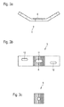
- FIG. 3a shows a horizontal section through the sheet metal cross member 5 in a schematic representation. Clearly visible is the center provided Tooth area 8, which is oriented towards the building when installed.
- Fig. 3b which shows the sheet metal crosshead 5 in frontal view in a schematic representation, the toothing region 8 is shown hatched.
- the metal traverse 5 has three openings 10, 11, 12. Like from the FIG. 1 can be seen, the opening 12 is provided to allow penetration of the metal sheet 5 through the connecting rod 3.
- the opening 10 allows penetration of the sheet metal cross member 5 through the connecting rod 4.
- the two openings 10, 12 are vertically slightly offset from each other to be able to record the two connecting rods without voltage.
- the opening provided in the toothing region 8 of the metal sheet 5 opening 11 serves the frictional connection of the armature 6 and the sheet metal cross-fifth
- the openings 10, 12 penetrating end portions of the connecting rods 3, 4 threads cut.
- a nut is first screwed, then the metal cross member 5 with the help of the corresponding openings on the two connecting rods 3, 4 attached and then screwed two more nuts.
- the metal cross-member 5 is so quenched between two times two nuts and fixed in this way safely and permanently.
- a toothed washer 9 can be seen.
- the armature 6 is guided through the opening of the washer 9.
- the toothing of the washer 9 is brought into engagement with the toothing of the metal cross-member 5 and in this way ensures a frictional connection of the metal cross-member 5 and the armature 6.
Landscapes
- Engineering & Computer Science (AREA)
- Architecture (AREA)
- Physics & Mathematics (AREA)
- Electromagnetism (AREA)
- Civil Engineering (AREA)
- Structural Engineering (AREA)
- Joining Of Building Structures In Genera (AREA)
- Buildings Adapted To Withstand Abnormal External Influences (AREA)
- Roof Covering Using Slabs Or Stiff Sheets (AREA)
- Building Environments (AREA)
- Connection Of Plates (AREA)
Claims (7)
- Elément de raccordement (1) de dalle destiné à assembler une partie de bâtiment avec une dalle posée à l'avant de la partie de bâtiment, comportant- un corps isolant (2) placé en position montée entre la partie de bâtiment et la dalle posée à l'avant,- au moins deux tiges de raccordement (3, 4) qui se croisent, saillant en position montée dans la partie de bâtiment ou dans la dalle posée à l'avant,- au moins une traverse en tôle (5) fixement reliée avec les tiges de raccordement (3, 4) et- une ancre (6) saillant en position montée dans la dalle posée à l'avant ou dans la partie de bâtiment, l'ancre (6) étant reliée par complémentarité de force avec la traverse en tôle (5),les au moins deux tiges de raccordement (3, 4) pénétrant dans le corps isolant (2) et se croisant dans la région du corps isolant (2),
caractérisé en ce que le corps isolant (2) est uniquement pénétré par les tiges de raccordement (3, 4) qui se croisent. - Elément de raccordement (1) de dalle selon la revendication 1, caractérisé en ce que les deux tiges de raccordement (3, 4) qui se croisent s'étendent sensiblement dans un plan, notamment sensiblement dans un plan horizontal ou sensiblement dans un plan vertical.
- Elément de raccordement (1) de dalle selon la revendication 1 ou 2, caractérisé en ce que l'ancre (6) pénètre dans la traverse en tôle (5) et/ou en ce que les tiges de raccordement (3, 4) pénètrent dans la traverse en tôle (5) et les tiges de raccordement (3, 4) sont vissées sur la traverse en tôle (5).
- Elément de raccordement (1) de dalle selon l'une quelconque des revendications 1 à 3, caractérisé en ce que la liaison par complémentarité de force de la traverse en tôle (5) avec l'ancre (6) s'effectue par l'intermédiaire d'une denture (7).
- Elément de raccordement (1) de dalle selon la revendication 4, caractérisé en ce que la traverse en tôle (5) comporte une région dentée (8) placée au centre.
- Elément de raccordement (1) de dalle selon la revendication 5, caractérisé en ce qu'il est prévu en supplément une rondelle (9) comportant une denture, qui en position montée s'engage par complémentarité de force dans la région dentée de la traverse en tôle (5).
- Agencement destiné à relier une partie de bâtiment avec une dalle posée à l'avant de la partie de bâtiment, comportant un élément de raccordement (1) de dalle selon l'une quelconque des revendications 1 à 6 et un élément de force vertical évacuant la charge agissant à la verticale de la dalle posée à l'avant, l'élément de force vertical étant notamment au moins un étançon évacuant dans le sous-sol la charge agissant à la verticale de la dalle posée à l'avant ou une suspension ou un étaiement évacuant dans le bâtiment la charge agissant à la verticale de la dalle posée à l'avant.
Applications Claiming Priority (1)
| Application Number | Priority Date | Filing Date | Title |
|---|---|---|---|
| DE102011056967A DE102011056967A1 (de) | 2011-12-23 | 2011-12-23 | Plattenanschlusselement |
Publications (3)
| Publication Number | Publication Date |
|---|---|
| EP2607560A2 EP2607560A2 (fr) | 2013-06-26 |
| EP2607560A3 EP2607560A3 (fr) | 2014-06-25 |
| EP2607560B1 true EP2607560B1 (fr) | 2016-03-16 |
Family
ID=47500973
Family Applications (1)
| Application Number | Title | Priority Date | Filing Date |
|---|---|---|---|
| EP12197493.5A Active EP2607560B1 (fr) | 2011-12-23 | 2012-12-17 | Élément de raccordement de dalle |
Country Status (2)
| Country | Link |
|---|---|
| EP (1) | EP2607560B1 (fr) |
| DE (1) | DE102011056967A1 (fr) |
Families Citing this family (2)
| Publication number | Priority date | Publication date | Assignee | Title |
|---|---|---|---|---|
| DE102014113662A1 (de) * | 2014-09-22 | 2016-03-24 | Max Frank Gmbh & Co. Kg | Anschlusselement |
| DE102019118363B4 (de) * | 2019-07-08 | 2021-07-15 | Max Frank Gmbh & Co. Kg | Anordnung zum Verbinden eines Bauwerkteils mit einem dem Bauwerkteil vorgelagerten Stahl-Außenteil |
Family Cites Families (7)
| Publication number | Priority date | Publication date | Assignee | Title |
|---|---|---|---|---|
| DE7006151U (de) * | 1970-02-20 | 1970-07-09 | Schuckmann Kg Werner A | Verankerung zur freihaengenden befestigung vorgefertigter wand- oder fassadenplatten. |
| DE3005571C2 (de) | 1980-02-14 | 1982-02-18 | Schöck, Eberhard, 7570 Baden-Baden | Bauelement zur Wärmedämmung bei Gebäuden |
| DE3700295C2 (de) * | 1987-01-07 | 1993-11-11 | Schoeck Bauteile Gmbh | Bauelement zur Isolierung bei Gebäuden |
| CH690448A5 (de) | 1996-04-22 | 2000-09-15 | Pecon Ag | Mehrteiliger Armierungsstab. |
| DE19718230B4 (de) * | 1996-07-17 | 2005-07-21 | Halfen Gmbh & Co. Kommanditgesellschaft | Befestigungselement zur Sicherung einer Kopfschraube in einer Ankerschiene |
| DE19908388B4 (de) * | 1999-02-26 | 2008-10-30 | Schöck Bauteile GmbH | Bauelement zur Wärmedämmung |
| DE10130866A1 (de) * | 2001-06-22 | 2003-01-02 | Schoeck Entwicklungsgmbh | Bauelement zur Wärmedämmung |
-
2011
- 2011-12-23 DE DE102011056967A patent/DE102011056967A1/de not_active Ceased
-
2012
- 2012-12-17 EP EP12197493.5A patent/EP2607560B1/fr active Active
Also Published As
| Publication number | Publication date |
|---|---|
| EP2607560A3 (fr) | 2014-06-25 |
| EP2607560A2 (fr) | 2013-06-26 |
| DE102011056967A1 (de) | 2013-06-27 |
Similar Documents
| Publication | Publication Date | Title |
|---|---|---|
| EP1832690B1 (fr) | Elément de construction pour isolation thermique | |
| DE102007016236B3 (de) | Abstandshalter zur Befestigung eines Halteelementes in einer Wandung | |
| EP0121685A2 (fr) | Elément soumis à la compression dans un élément de construction isolant pour parties de bâtiment faisant ressaut | |
| EP4067593A1 (fr) | Dispositif de liaison ultérieure à isolation thermique et à transfert de force d'une seconde partie d'ouvrage supportant la charge à une première partie d'ouvrage supportant la charge et ouvrage doté d'un tel dispositif | |
| EP2055845A2 (fr) | Elément de montage de dalles en porte-à-faux | |
| EP3754125B1 (fr) | Élément de construction pour le montage dans des joints de dilatation de bâtiments | |
| EP1270833B1 (fr) | Elément de construction pour l'isolation thermique | |
| EP2607560A2 (fr) | Elément de raccordement de dalle | |
| DE102019133999A1 (de) | Anordnung zum Verbinden eines Bauwerkteils mit einem dem Bauwerkteil vorgelagerten Außenteil | |
| DE202007012823U1 (de) | Bauteilanschluss | |
| DE102011054275A1 (de) | Kragplattenanschlusselement | |
| EP1992753B9 (fr) | Bâtiment, comprenant un système de façade résistant aux explosions | |
| DE102004040584A1 (de) | Bauelement zur Schubbewehrung | |
| DE102019118363B4 (de) | Anordnung zum Verbinden eines Bauwerkteils mit einem dem Bauwerkteil vorgelagerten Stahl-Außenteil | |
| EP2069581B2 (fr) | Construction en béton armé pour un bâtiment | |
| DE102010027368B4 (de) | Vorrichtung zur Eckbefestigung einer Leibungsplatte | |
| EP3835501B1 (fr) | Arrangement pour connecter une pièce de construction avec une partie extérieure frontale | |
| EP2379824B1 (fr) | Ancre de fixation destinée à la fixation d'une façade | |
| EP2998450B1 (fr) | Élement de raccordement | |
| DE29909395U1 (de) | Vorrichtung zur Eckbefestigung einer Leibungsplatte | |
| EP2369073B1 (fr) | Élément de pose de dalles en console | |
| EP3839162A1 (fr) | Composant thermo-isolant destiné à être utilisé dans une fente de séparation entre deux parties de construction et construction | |
| EP3569783B1 (fr) | Composant destiné à l'isolation thermique | |
| EP3611310B1 (fr) | Ancre de garde-corps | |
| EP4299861A1 (fr) | Dispositif et procédé de renforcement ultérieur d'un composant doté d'au moins une zone de discontinuité |
Legal Events
| Date | Code | Title | Description |
|---|---|---|---|
| AK | Designated contracting states |
Kind code of ref document: A2 Designated state(s): AL AT BE BG CH CY CZ DE DK EE ES FI FR GB GR HR HU IE IS IT LI LT LU LV MC MK MT NL NO PL PT RO RS SE SI SK SM TR |
|
| AX | Request for extension of the european patent |
Extension state: BA ME |
|
| PUAI | Public reference made under article 153(3) epc to a published international application that has entered the european phase |
Free format text: ORIGINAL CODE: 0009012 |
|
| PUAL | Search report despatched |
Free format text: ORIGINAL CODE: 0009013 |
|
| AK | Designated contracting states |
Kind code of ref document: A3 Designated state(s): AL AT BE BG CH CY CZ DE DK EE ES FI FR GB GR HR HU IE IS IT LI LT LU LV MC MK MT NL NO PL PT RO RS SE SI SK SM TR |
|
| AX | Request for extension of the european patent |
Extension state: BA ME |
|
| RIC1 | Information provided on ipc code assigned before grant |
Ipc: E04B 1/41 20060101ALI20140521BHEP Ipc: E04B 1/00 20060101AFI20140521BHEP |
|
| 17P | Request for examination filed |
Effective date: 20150105 |
|
| RBV | Designated contracting states (corrected) |
Designated state(s): AL AT BE BG CH CY CZ DE DK EE ES FI FR GB GR HR HU IE IS IT LI LT LU LV MC MK MT NL NO PL PT RO RS SE SI SK SM TR |
|
| GRAP | Despatch of communication of intention to grant a patent |
Free format text: ORIGINAL CODE: EPIDOSNIGR1 |
|
| INTG | Intention to grant announced |
Effective date: 20151105 |
|
| GRAS | Grant fee paid |
Free format text: ORIGINAL CODE: EPIDOSNIGR3 |
|
| GRAA | (expected) grant |
Free format text: ORIGINAL CODE: 0009210 |
|
| AK | Designated contracting states |
Kind code of ref document: B1 Designated state(s): AL AT BE BG CH CY CZ DE DK EE ES FI FR GB GR HR HU IE IS IT LI LT LU LV MC MK MT NL NO PL PT RO RS SE SI SK SM TR |
|
| REG | Reference to a national code |
Ref country code: GB Ref legal event code: FG4D Free format text: NOT ENGLISH |
|
| REG | Reference to a national code |
Ref country code: CH Ref legal event code: EP |
|
| REG | Reference to a national code |
Ref country code: IE Ref legal event code: FG4D Free format text: LANGUAGE OF EP DOCUMENT: GERMAN |
|
| REG | Reference to a national code |
Ref country code: AT Ref legal event code: REF Ref document number: 781399 Country of ref document: AT Kind code of ref document: T Effective date: 20160415 Ref country code: CH Ref legal event code: NV Representative=s name: MICHELI AND CIE SA, CH |
|
| REG | Reference to a national code |
Ref country code: SE Ref legal event code: TRGR |
|
| REG | Reference to a national code |
Ref country code: DE Ref legal event code: R096 Ref document number: 502012006283 Country of ref document: DE |
|
| REG | Reference to a national code |
Ref country code: NL Ref legal event code: MP Effective date: 20160316 |
|
| REG | Reference to a national code |
Ref country code: LT Ref legal event code: MG4D |
|
| PG25 | Lapsed in a contracting state [announced via postgrant information from national office to epo] |
Ref country code: FI Free format text: LAPSE BECAUSE OF FAILURE TO SUBMIT A TRANSLATION OF THE DESCRIPTION OR TO PAY THE FEE WITHIN THE PRESCRIBED TIME-LIMIT Effective date: 20160316 Ref country code: GR Free format text: LAPSE BECAUSE OF FAILURE TO SUBMIT A TRANSLATION OF THE DESCRIPTION OR TO PAY THE FEE WITHIN THE PRESCRIBED TIME-LIMIT Effective date: 20160617 Ref country code: NO Free format text: LAPSE BECAUSE OF FAILURE TO SUBMIT A TRANSLATION OF THE DESCRIPTION OR TO PAY THE FEE WITHIN THE PRESCRIBED TIME-LIMIT Effective date: 20160616 Ref country code: HR Free format text: LAPSE BECAUSE OF FAILURE TO SUBMIT A TRANSLATION OF THE DESCRIPTION OR TO PAY THE FEE WITHIN THE PRESCRIBED TIME-LIMIT Effective date: 20160316 |
|
| PG25 | Lapsed in a contracting state [announced via postgrant information from national office to epo] |
Ref country code: NL Free format text: LAPSE BECAUSE OF FAILURE TO SUBMIT A TRANSLATION OF THE DESCRIPTION OR TO PAY THE FEE WITHIN THE PRESCRIBED TIME-LIMIT Effective date: 20160316 Ref country code: RS Free format text: LAPSE BECAUSE OF FAILURE TO SUBMIT A TRANSLATION OF THE DESCRIPTION OR TO PAY THE FEE WITHIN THE PRESCRIBED TIME-LIMIT Effective date: 20160316 Ref country code: LV Free format text: LAPSE BECAUSE OF FAILURE TO SUBMIT A TRANSLATION OF THE DESCRIPTION OR TO PAY THE FEE WITHIN THE PRESCRIBED TIME-LIMIT Effective date: 20160316 Ref country code: LT Free format text: LAPSE BECAUSE OF FAILURE TO SUBMIT A TRANSLATION OF THE DESCRIPTION OR TO PAY THE FEE WITHIN THE PRESCRIBED TIME-LIMIT Effective date: 20160316 |
|
| PG25 | Lapsed in a contracting state [announced via postgrant information from national office to epo] |
Ref country code: IS Free format text: LAPSE BECAUSE OF FAILURE TO SUBMIT A TRANSLATION OF THE DESCRIPTION OR TO PAY THE FEE WITHIN THE PRESCRIBED TIME-LIMIT Effective date: 20160716 Ref country code: EE Free format text: LAPSE BECAUSE OF FAILURE TO SUBMIT A TRANSLATION OF THE DESCRIPTION OR TO PAY THE FEE WITHIN THE PRESCRIBED TIME-LIMIT Effective date: 20160316 Ref country code: PL Free format text: LAPSE BECAUSE OF FAILURE TO SUBMIT A TRANSLATION OF THE DESCRIPTION OR TO PAY THE FEE WITHIN THE PRESCRIBED TIME-LIMIT Effective date: 20160316 |
|
| PG25 | Lapsed in a contracting state [announced via postgrant information from national office to epo] |
Ref country code: CZ Free format text: LAPSE BECAUSE OF FAILURE TO SUBMIT A TRANSLATION OF THE DESCRIPTION OR TO PAY THE FEE WITHIN THE PRESCRIBED TIME-LIMIT Effective date: 20160316 Ref country code: PT Free format text: LAPSE BECAUSE OF FAILURE TO SUBMIT A TRANSLATION OF THE DESCRIPTION OR TO PAY THE FEE WITHIN THE PRESCRIBED TIME-LIMIT Effective date: 20160718 Ref country code: SK Free format text: LAPSE BECAUSE OF FAILURE TO SUBMIT A TRANSLATION OF THE DESCRIPTION OR TO PAY THE FEE WITHIN THE PRESCRIBED TIME-LIMIT Effective date: 20160316 Ref country code: ES Free format text: LAPSE BECAUSE OF FAILURE TO SUBMIT A TRANSLATION OF THE DESCRIPTION OR TO PAY THE FEE WITHIN THE PRESCRIBED TIME-LIMIT Effective date: 20160316 Ref country code: SM Free format text: LAPSE BECAUSE OF FAILURE TO SUBMIT A TRANSLATION OF THE DESCRIPTION OR TO PAY THE FEE WITHIN THE PRESCRIBED TIME-LIMIT Effective date: 20160316 Ref country code: RO Free format text: LAPSE BECAUSE OF FAILURE TO SUBMIT A TRANSLATION OF THE DESCRIPTION OR TO PAY THE FEE WITHIN THE PRESCRIBED TIME-LIMIT Effective date: 20160316 |
|
| REG | Reference to a national code |
Ref country code: DE Ref legal event code: R097 Ref document number: 502012006283 Country of ref document: DE |
|
| PG25 | Lapsed in a contracting state [announced via postgrant information from national office to epo] |
Ref country code: IT Free format text: LAPSE BECAUSE OF FAILURE TO SUBMIT A TRANSLATION OF THE DESCRIPTION OR TO PAY THE FEE WITHIN THE PRESCRIBED TIME-LIMIT Effective date: 20160316 |
|
| PLBE | No opposition filed within time limit |
Free format text: ORIGINAL CODE: 0009261 |
|
| STAA | Information on the status of an ep patent application or granted ep patent |
Free format text: STATUS: NO OPPOSITION FILED WITHIN TIME LIMIT |
|
| PG25 | Lapsed in a contracting state [announced via postgrant information from national office to epo] |
Ref country code: DK Free format text: LAPSE BECAUSE OF FAILURE TO SUBMIT A TRANSLATION OF THE DESCRIPTION OR TO PAY THE FEE WITHIN THE PRESCRIBED TIME-LIMIT Effective date: 20160316 |
|
| 26N | No opposition filed |
Effective date: 20161219 |
|
| PG25 | Lapsed in a contracting state [announced via postgrant information from national office to epo] |
Ref country code: BG Free format text: LAPSE BECAUSE OF FAILURE TO SUBMIT A TRANSLATION OF THE DESCRIPTION OR TO PAY THE FEE WITHIN THE PRESCRIBED TIME-LIMIT Effective date: 20160616 |
|
| PG25 | Lapsed in a contracting state [announced via postgrant information from national office to epo] |
Ref country code: BE Free format text: LAPSE BECAUSE OF NON-PAYMENT OF DUE FEES Effective date: 20161231 Ref country code: SI Free format text: LAPSE BECAUSE OF FAILURE TO SUBMIT A TRANSLATION OF THE DESCRIPTION OR TO PAY THE FEE WITHIN THE PRESCRIBED TIME-LIMIT Effective date: 20160316 |
|
| PG25 | Lapsed in a contracting state [announced via postgrant information from national office to epo] |
Ref country code: MC Free format text: LAPSE BECAUSE OF FAILURE TO SUBMIT A TRANSLATION OF THE DESCRIPTION OR TO PAY THE FEE WITHIN THE PRESCRIBED TIME-LIMIT Effective date: 20160316 |
|
| REG | Reference to a national code |
Ref country code: FR Ref legal event code: ST Effective date: 20170831 |
|
| REG | Reference to a national code |
Ref country code: IE Ref legal event code: MM4A |
|
| PG25 | Lapsed in a contracting state [announced via postgrant information from national office to epo] |
Ref country code: FR Free format text: LAPSE BECAUSE OF NON-PAYMENT OF DUE FEES Effective date: 20170102 Ref country code: LU Free format text: LAPSE BECAUSE OF NON-PAYMENT OF DUE FEES Effective date: 20161217 |
|
| PG25 | Lapsed in a contracting state [announced via postgrant information from national office to epo] |
Ref country code: IE Free format text: LAPSE BECAUSE OF NON-PAYMENT OF DUE FEES Effective date: 20161217 |
|
| REG | Reference to a national code |
Ref country code: BE Ref legal event code: MM Effective date: 20161231 |
|
| PG25 | Lapsed in a contracting state [announced via postgrant information from national office to epo] |
Ref country code: HU Free format text: LAPSE BECAUSE OF FAILURE TO SUBMIT A TRANSLATION OF THE DESCRIPTION OR TO PAY THE FEE WITHIN THE PRESCRIBED TIME-LIMIT; INVALID AB INITIO Effective date: 20121217 Ref country code: CY Free format text: LAPSE BECAUSE OF FAILURE TO SUBMIT A TRANSLATION OF THE DESCRIPTION OR TO PAY THE FEE WITHIN THE PRESCRIBED TIME-LIMIT Effective date: 20160316 |
|
| PG25 | Lapsed in a contracting state [announced via postgrant information from national office to epo] |
Ref country code: TR Free format text: LAPSE BECAUSE OF FAILURE TO SUBMIT A TRANSLATION OF THE DESCRIPTION OR TO PAY THE FEE WITHIN THE PRESCRIBED TIME-LIMIT Effective date: 20160316 Ref country code: MK Free format text: LAPSE BECAUSE OF FAILURE TO SUBMIT A TRANSLATION OF THE DESCRIPTION OR TO PAY THE FEE WITHIN THE PRESCRIBED TIME-LIMIT Effective date: 20160316 |
|
| PG25 | Lapsed in a contracting state [announced via postgrant information from national office to epo] |
Ref country code: MT Free format text: LAPSE BECAUSE OF FAILURE TO SUBMIT A TRANSLATION OF THE DESCRIPTION OR TO PAY THE FEE WITHIN THE PRESCRIBED TIME-LIMIT Effective date: 20160316 |
|
| PG25 | Lapsed in a contracting state [announced via postgrant information from national office to epo] |
Ref country code: AL Free format text: LAPSE BECAUSE OF FAILURE TO SUBMIT A TRANSLATION OF THE DESCRIPTION OR TO PAY THE FEE WITHIN THE PRESCRIBED TIME-LIMIT Effective date: 20160316 |
|
| PGFP | Annual fee paid to national office [announced via postgrant information from national office to epo] |
Ref country code: SE Payment date: 20191219 Year of fee payment: 8 |
|
| PGFP | Annual fee paid to national office [announced via postgrant information from national office to epo] |
Ref country code: AT Payment date: 20191220 Year of fee payment: 8 |
|
| PGFP | Annual fee paid to national office [announced via postgrant information from national office to epo] |
Ref country code: GB Payment date: 20191220 Year of fee payment: 8 |
|
| REG | Reference to a national code |
Ref country code: SE Ref legal event code: EUG |
|
| REG | Reference to a national code |
Ref country code: AT Ref legal event code: MM01 Ref document number: 781399 Country of ref document: AT Kind code of ref document: T Effective date: 20201217 |
|
| GBPC | Gb: european patent ceased through non-payment of renewal fee |
Effective date: 20201217 |
|
| PG25 | Lapsed in a contracting state [announced via postgrant information from national office to epo] |
Ref country code: AT Free format text: LAPSE BECAUSE OF NON-PAYMENT OF DUE FEES Effective date: 20201217 |
|
| PG25 | Lapsed in a contracting state [announced via postgrant information from national office to epo] |
Ref country code: GB Free format text: LAPSE BECAUSE OF NON-PAYMENT OF DUE FEES Effective date: 20201217 Ref country code: SE Free format text: LAPSE BECAUSE OF NON-PAYMENT OF DUE FEES Effective date: 20201218 |
|
| P01 | Opt-out of the competence of the unified patent court (upc) registered |
Effective date: 20230522 |
|
| REG | Reference to a national code |
Ref country code: CH Ref legal event code: U11 Free format text: ST27 STATUS EVENT CODE: U-0-0-U10-U11 (AS PROVIDED BY THE NATIONAL OFFICE) Effective date: 20260101 |
|
| PGFP | Annual fee paid to national office [announced via postgrant information from national office to epo] |
Ref country code: DE Payment date: 20251230 Year of fee payment: 14 |
|
| PGFP | Annual fee paid to national office [announced via postgrant information from national office to epo] |
Ref country code: CH Payment date: 20260101 Year of fee payment: 14 |