EP3835520A1 - Fahrzeugtürgriff - Google Patents
Fahrzeugtürgriff Download PDFInfo
- Publication number
- EP3835520A1 EP3835520A1 EP19847932.1A EP19847932A EP3835520A1 EP 3835520 A1 EP3835520 A1 EP 3835520A1 EP 19847932 A EP19847932 A EP 19847932A EP 3835520 A1 EP3835520 A1 EP 3835520A1
- Authority
- EP
- European Patent Office
- Prior art keywords
- back covers
- door handle
- locking
- vehicle door
- locked
- Prior art date
- Legal status (The legal status is an assumption and is not a legal conclusion. Google has not performed a legal analysis and makes no representation as to the accuracy of the status listed.)
- Pending
Links
Images


Classifications
-
- E—FIXED CONSTRUCTIONS
- E05—LOCKS; KEYS; WINDOW OR DOOR FITTINGS; SAFES
- E05B—LOCKS; ACCESSORIES THEREFOR; HANDCUFFS
- E05B81/00—Power-actuated vehicle locks
- E05B81/54—Electrical circuits
- E05B81/64—Monitoring or sensing, e.g. by using switches or sensors
- E05B81/76—Detection of handle operation; Detection of a user approaching a handle; Electrical switching actions performed by door handles
- E05B81/78—Detection of handle operation; Detection of a user approaching a handle; Electrical switching actions performed by door handles as part of a hands-free locking or unlocking operation
-
- E—FIXED CONSTRUCTIONS
- E05—LOCKS; KEYS; WINDOW OR DOOR FITTINGS; SAFES
- E05B—LOCKS; ACCESSORIES THEREFOR; HANDCUFFS
- E05B79/00—Mounting or connecting vehicle locks or parts thereof
- E05B79/02—Mounting of vehicle locks or parts thereof
- E05B79/06—Mounting of handles, e.g. to the wing or to the lock
-
- E—FIXED CONSTRUCTIONS
- E05—LOCKS; KEYS; WINDOW OR DOOR FITTINGS; SAFES
- E05B—LOCKS; ACCESSORIES THEREFOR; HANDCUFFS
- E05B85/00—Details of vehicle locks not provided for in groups E05B77/00 - E05B83/00
- E05B85/10—Handles
- E05B85/14—Handles pivoted about an axis parallel to the wing
- E05B85/16—Handles pivoted about an axis parallel to the wing a longitudinal grip part being pivoted at one end about an axis perpendicular to the longitudinal axis of the grip part
-
- B—PERFORMING OPERATIONS; TRANSPORTING
- B60—VEHICLES IN GENERAL
- B60R—VEHICLES, VEHICLE FITTINGS, OR VEHICLE PARTS, NOT OTHERWISE PROVIDED FOR
- B60R16/00—Electric or fluid circuits specially adapted for vehicles and not otherwise provided for; Arrangement of elements of electric or fluid circuits specially adapted for vehicles and not otherwise provided for
- B60R16/02—Electric or fluid circuits specially adapted for vehicles and not otherwise provided for; Arrangement of elements of electric or fluid circuits specially adapted for vehicles and not otherwise provided for electric constitutive elements
- B60R16/0207—Wire harnesses
- B60R16/0215—Protecting, fastening and routing means therefor
Definitions
- the present invention relates to a vehicle door handle.
- Patent Literature 1 As a door handle formed by connecting front and back covers, a door handle disclosed in Patent Literature 1 is known.
- An embodiment of the present invention provides a vehicle door handle formed by connecting front and back covers 1, 2.
- One of the front and back covers 1, 2 includes a locking body.
- the locking body includes a leg portion 3 configured to elastically deform and a locking hook 4 projecting from a tip end of the leg portion.
- the locking hook 4 is elastically locked and connected to a locked portion 6 formed on the other of the front and back covers.
- the locking body 5 is biased and the locking hook 4 is press-contacted to the locked portion 6 in a locking state of the locking body 5 and the locked portion 6.
- one of the front and back covers 1, 2 includes the locking body 5 in which the locking hook 4 projects from the tip end of the leg portion 3 configured to elastically deform, only by overlapping the front and back covers 1, 2, the locking hook 4 of the locking body 5 interferes with the locked portion 6 of the other of the front and back covers 1, 2, the leg portion 3 is elastically deformed once, and then returns to an original position by an elastic restoring force, the locking hook 4 is locked to the locked portion 6, and a connected state of the front and back covers 1, 2 is held.
- a biasing force in a locking direction is applied to the locking body 5 in the connected state, even when the gap is formed, the locking body 5 is biased in the locking direction after the gap is formed, so that the gap is absorbed and the locking is brought into a press-contact state.
- An application of a press-contact force to the locking body 5 can be implemented by, for example, in a cover on which the locking body 5 is formed, setting a member that elastically deforms and presses against a cover on an opposite side at a completion of the connection operation, but when the locking body 5 is erected on the support base 7 which is configured to elastically deform in a press-contact direction of the locking hook 4, the structure is simplified.
- the back cover 2 of the front and back covers 1, 2 may include the support base 7.
- the support base 7 may have a pressing portion 8 which is pressed toward a front cover 1 side when the front and back covers are connected. It is possible to reliably prevent the support base 7 from being elastically deformed due to contact of the locking hook 4 with the locked portion 6 when the front and back covers 1 and 2 are overlapped and the locking from becoming incomplete.
- An electrical component 9 may be fixed to the one or the other of the front and back covers 1, 2.
- the other of the front and back covers 1, 2 may include a harness holding portion 11 holding a harness 10 of the electrical component 9.
- the harness holding portion 11 may include stopper projections 13 projecting from tip ends of a pair of rising pieces 12 disposed along a width direction of the front and back covers 1, 2 in a facing direction.
- the harness holding portion 11 and the locked portion 6 may be disposed along the width direction. Since the harness 10 can be prevented from being caught when the front and back covers 1 and 2 are overlapped, the work efficiency is improved.
- a parting surface of a molding die is disposed at appropriate positions in an overlapping direction, that is, in a front-back direction, so that the stopper projection required to prevent the harness 10 from popping out of the harness holding portion 11 is an undercut portion with respect to an one-sided split surface.
- the undercut portion it is necessary to use a slide mold or the like that slides parallel to the one-sided split surface.
- the locked portion 6 also similarly forms the undercut portion with respect to the one-sided split surface, similarly, it is necessary to use a slide mold or the like, but by disposing the harness holding portion 11 and the locked portion 6 side by side in the width direction, the undercut portion can be processed by the same slide mold, so that a structure of a die can be simplified.
- the one of the front and back covers may include an elastic piece 15 in a vicinity of an end part of the one or the other of the front and back covers 1, 2, and in a vicinity of the support base 7.
- a free end of the elastic piece 15 may be press-contacted to an inclined surface 14 formed on the other of the front and back covers 1, 2, when the front and back covers are connected.
- the front and back covers may be biased in a longitudinal direction by an elastic restoring force of the elastic piece 15, slide stoppers 16 formed on the front and back covers 1, 2 may be pressed-contacted to each other, a biasing force in a detachment direction is applied to the front and back covers, and a contact pressure between the locking hook 4 and the locked portion 6 may be increased.
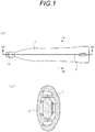
- a vehicle door handle is connected to a door in a posture in which a left side in Fig. 1(a) faces a front of a vehicle by using a handle attachment component (not shown) (in this specification, “front and rear” and “front and back” are defined based on an attachment posture to the vehicle).
- the door maintains a closed state by locking a door latch device (not shown) to a vehicle body, and in a connected state, the door handle is horizontally rotated around a rotation center to release locking of the door latch device.
- an electrical component 9 is attached inside the door handle.
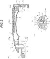
- an antenna 9A used for communication with a portable transmission device carried by a user and a switch 9B to be press-contacted when the door latch device is moved to a locked state are accommodated, and a harness 10 to be described later is pulled out to the outside of the door handle.
- the door handle has a C-shaped cross section, and is formed by connecting a front cover 1 that provides an outer surface shape in a front view in a state of being attached to the door and a back cover 2 that provides a hand hooking portion at the time of operation.
- the back cover 2 is formed in a shape capable of closing an open portion of a back surface of the front cover 1.
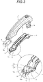
- the back cover 2 is made of a synthetic resin material, and, as shown in Figs. 3 to 4 , a pair of locking bodies 5 are provided at symmetrical positions with respect to a longitudinal center line (C) at a front end portion.
- the locking bodies 5 are formed by projecting locking hooks 4 in a facing direction from tip ends of leg portions 3 which are elastically deformable by elasticity of a material of the back cover 2.
- the locking body 5 is formed in a cantilever shape having one end edge as a fixed end, and is formed on an elastically deformable support base 7.
- a back surface of the support base 7 is a pressing portion 8 for elastically deforming and pushing the entire support base 7 toward a front surface side.
- a pair of elastic pieces 15 are provided at symmetrical positions with respect to a longitudinal center at a tip end portion of the back cover 2.
- a tip end of the elastic piece 15 is erected toward the front surface side, and a press-contact projection 15a bulges forward toward the tip end.
- a projecting piece 17 is extended from a rear end edge portion of the back cover 2 to a back surface side, and an insertion projecting piece 17a is projected rearward from a tip end portion thereof, and a slide stopper 16 is formed at a lower end of the projecting piece 17.
- the front cover 1 includes a hinge projecting piece 1a at the front end portion and an operating leg portion 1b at a rear end portion.
- a recess 1c into which the insertion projecting piece 17a of the back cover 2 can be inserted is formed in the operating leg portion 1b.
- the slide stopper 16 of the back cover 2 is formed so that the slide stopper 16 can come into contact with a front end surface of the recess 1c.
- the hinge projecting piece 1a provides a rotation center while being mounted on the door by sliding an arc portion 18 that bulges toward the front surface side to an attachment component.
- the operating leg portion 1b operates the door latch device by operating an operation component (not shown) such as a lever provided on the attachment component when rotation is performed around the rotation center.
- an inclined surface 14 that gradually moves toward the front surface side as going rearward is formed in a hatched area in Fig. 5 .
- the inclined surface 14 is disposed at a position where the press-contact projection 15a of the back cover 2 can come into contact with the inclined surface 14.
- the antenna 9A and the switch 9B are fixed to the front cover 1, and as shown in Fig. 5 , the harness 10 pulled out from the antenna 9A and the switch 9B is pulled out to the outside of the door handle after a variation is prevented by a harness holding portion 11 formed at the front end portion.
- the harness holding portion 11 is formed by projecting stopper projections 13 at tip ends of a pair of rising pieces 12 erected from a back surface wall of the front cover 1.
- the rising pieces 12 are disposed side by side in a width direction (a direction orthogonal to a longitudinal direction of the door handle, in this example, at symmetrical positions with respect to the longitudinal center line (C) of the door handle) as shown in Fig. 5 , and the stopper projections 13 are disposed so that projecting ends face each other.
- the front cover 1 is provided with locked portions 6 to which the locking hook 4 of the locking body 5 provided on the back cover 2 can be locked.
- the locked portions 6 are formed as an inward projection so as to be lockable with the locking hook 4 protruding outward, and are disposed side by side in the width direction as shown in Fig. 5 .
- the locked portion 6 is undercut similarly as the stopper projection 13 of the harness holding portion 11 with respect to a parting surface (PL) of a molding die for manufacturing the front cover 1.
- PL parting surface
- both of the harness holding portion 11 and the locked portion 6 can be molded by one slide mold, and thus a structure of the molding die can be simplified.
- the insertion projecting piece 17a of the back cover 2 is fitted into the recess 1c of the front cover 1, and then the insertion projecting piece 17a is rotated about a fitting portion as a rotation center so that front end portions of the insertion projecting piece 17a and the fitting portion are overlapped with each other.
- the support base 7 In a locked state, the support base 7 returns to an original position by an elastic restoring force. Since the support base 7 in a state before deformation is set such that the locking hook 4 is positioned slightly on the back surface side relative to the locked portion 6, when the support base 7 is returned to the original position in a state where the locking hook 4 is locked to the locked portion 6, the locking hook 4 is pulled to the back surface side, a contact pressure between the locking hook 4 and the locked portion 6 increases, and rattling in an overlapping direction is completely prevented.
- the press-contact projection 15a of the back cover 2 is press-contacted against the inclined surface 14 of the front cover 1 and the elastic piece 15 is elastically deformed, and a force in a direction substantially orthogonal to the inclined surface 14 is generated by a restoring force thereof.
- the back cover 2 is press-contacted rearward by the component force in the longitudinal direction of the door handle of the force received from the inclined surface 14.
- slide stoppers 16 of the front and back covers 1 and 2 come into press-contact with each other, thereby preventing the rattling in the longitudinal direction of the door handle.
Landscapes
- Engineering & Computer Science (AREA)
- Mechanical Engineering (AREA)
- Lock And Its Accessories (AREA)
Applications Claiming Priority (2)
| Application Number | Priority Date | Filing Date | Title |
|---|---|---|---|
| JP2018149429A JP7064993B2 (ja) | 2018-08-08 | 2018-08-08 | 車両のドアハンドル |
| PCT/JP2019/031504 WO2020032214A1 (ja) | 2018-08-08 | 2019-08-08 | 車両のドアハンドル |
Publications (2)
| Publication Number | Publication Date |
|---|---|
| EP3835520A1 true EP3835520A1 (de) | 2021-06-16 |
| EP3835520A4 EP3835520A4 (de) | 2022-05-04 |
Family
ID=69414916
Family Applications (1)
| Application Number | Title | Priority Date | Filing Date |
|---|---|---|---|
| EP19847932.1A Pending EP3835520A4 (de) | 2018-08-08 | 2019-08-08 | Fahrzeugtürgriff |
Country Status (5)
| Country | Link |
|---|---|
| US (1) | US12331568B2 (de) |
| EP (1) | EP3835520A4 (de) |
| JP (1) | JP7064993B2 (de) |
| CN (1) | CN112534110A (de) |
| WO (1) | WO2020032214A1 (de) |
Families Citing this family (2)
| Publication number | Priority date | Publication date | Assignee | Title |
|---|---|---|---|---|
| CN117480305A (zh) * | 2021-07-02 | 2024-01-30 | 阿尔卑斯阿尔派株式会社 | 检测装置以及门把手 |
| EP4571025A1 (de) * | 2023-12-15 | 2025-06-18 | Minebea AccessSolutions France | Fahrzeugtürgriffanordnung |
Family Cites Families (28)
| Publication number | Priority date | Publication date | Assignee | Title |
|---|---|---|---|---|
| JPH0793505B2 (ja) * | 1990-11-09 | 1995-10-09 | 松下電器産業株式会社 | ロック解除機構付ツメ状ロック装置 |
| US5348356A (en) * | 1993-04-02 | 1994-09-20 | Apple Computer, Inc. | Hidden, releasable latch for a molded plastic enclosure |
| JP2004232300A (ja) * | 2003-01-29 | 2004-08-19 | Aisin Seiki Co Ltd | アウトサイドハンドル装置 |
| JP4015568B2 (ja) * | 2003-01-29 | 2007-11-28 | アイシン精機株式会社 | アウトサイドハンドル装置及びそのコネクタ構造 |
| JP4342207B2 (ja) * | 2003-04-22 | 2009-10-14 | アイシン精機株式会社 | 車両用ドアハンドル装置 |
| FR2869059B1 (fr) * | 2004-04-14 | 2006-06-30 | Fabi Automobile Soc Par Action | Mecanisme d'ouverture/fermeture de portiere de vehicule automobile |
| DE202005007586U1 (de) * | 2005-05-13 | 2005-08-04 | Rösler, Peter | Behälter mit Rastverschluss |
| CN1924261B (zh) * | 2005-08-31 | 2011-07-06 | 株式会社有信 | 车辆用门把手装置 |
| JP4882370B2 (ja) * | 2005-12-27 | 2012-02-22 | アイシン精機株式会社 | 車両用ドアハンドル |
| DE102006055100A1 (de) * | 2006-11-21 | 2008-05-29 | Kiekert Ag | Türgriff mit Blende und Elektronikbauteil-Träger |
| DE102007011080A1 (de) * | 2007-03-07 | 2008-09-11 | Huf Hülsbeck & Fürst Gmbh & Co. Kg | Außengriff an Türen oder Klappen von Fahrzeugen |
| JP5420961B2 (ja) * | 2009-04-09 | 2014-02-19 | 株式会社アルファ | 車両のドア操作ハンドル |
| JP5382374B2 (ja) * | 2011-06-22 | 2014-01-08 | アイシン精機株式会社 | 車両用ドアハンドル |
| DE102012102485A1 (de) * | 2012-03-22 | 2013-09-26 | Huf Hülsbeck & Fürst Gmbh & Co. Kg | Handhabe eines Kraftfahrzeuges mit einem bewegbaren Abdeckelement |
| JP5985874B2 (ja) * | 2012-04-27 | 2016-09-06 | 株式会社アルファ | 車両用ハンドル |
| CN202788193U (zh) * | 2012-09-11 | 2013-03-13 | 廖倚云 | 带指纹锁的汽车把手 |
| DE102013203166B4 (de) * | 2013-02-26 | 2020-01-30 | Kiekert Ag | Bowdenzug |
| JP5932708B2 (ja) * | 2013-04-22 | 2016-06-08 | 株式会社ホンダロック | 車両用ドアのアウトハンドル装置 |
| DE102013009225A1 (de) * | 2013-05-31 | 2014-12-04 | Kiekert Aktiengesellschaft | Bowdenzuglager für ein Kraftfahrzeugschloss |
| US20140366326A1 (en) * | 2013-06-13 | 2014-12-18 | GM Global Technology Operations LLC | Elastically deformable retaining hook for components to be mated together and method of assembling |
| JP6368951B2 (ja) * | 2014-03-13 | 2018-08-08 | 三井金属アクト株式会社 | 車両用ドアラッチ装置 |
| JP6499827B2 (ja) * | 2014-03-14 | 2019-04-10 | 株式会社アルファ | 車両のドアハンドル |
| EP3078794B1 (de) * | 2015-04-08 | 2017-12-20 | Illinois Tool Works Inc. | Schwenkvorrichtung für ein kraftfahrzeug mit einfach zu montierender und zugleich sicherer schwenklagerung |
| JP6222851B2 (ja) * | 2015-04-10 | 2017-11-01 | サカエ理研工業株式会社 | 車両用ドアハンドル部材 |
| JP2018112026A (ja) * | 2017-01-13 | 2018-07-19 | 株式会社アルファ | 車両用ドアハンドル部材及び車両用外装部材 |
| JP6683654B2 (ja) * | 2017-06-20 | 2020-04-22 | 株式会社ホンダロック | 車両用ドアのアウトハンドル装置 |
| DE102018105550A1 (de) * | 2018-03-09 | 2019-09-12 | BROSE SCHLIEßSYSTEME GMBH & CO. KG | Bowdenzugendstück |
| JP6521157B2 (ja) | 2018-07-06 | 2019-05-29 | 株式会社三洋物産 | 遊技機 |
-
2018
- 2018-08-08 JP JP2018149429A patent/JP7064993B2/ja active Active
-
2019
- 2019-08-08 EP EP19847932.1A patent/EP3835520A4/de active Pending
- 2019-08-08 CN CN201980052035.0A patent/CN112534110A/zh active Pending
- 2019-08-08 WO PCT/JP2019/031504 patent/WO2020032214A1/ja not_active Ceased
-
2021
- 2021-02-05 US US17/168,375 patent/US12331568B2/en active Active
Also Published As
| Publication number | Publication date |
|---|---|
| JP2020023846A (ja) | 2020-02-13 |
| WO2020032214A1 (ja) | 2020-02-13 |
| US20210156180A1 (en) | 2021-05-27 |
| EP3835520A4 (de) | 2022-05-04 |
| US12331568B2 (en) | 2025-06-17 |
| CN112534110A (zh) | 2021-03-19 |
| JP7064993B2 (ja) | 2022-05-11 |
Similar Documents
| Publication | Publication Date | Title |
|---|---|---|
| US5401179A (en) | Locking mechanism for a connector assembly of low engaging/disengaging force type | |
| US11066852B2 (en) | Vehicle door handle device | |
| JP2003174906A (ja) | 3つの分岐部を有する安全ベルト用、特に自動車等に幼児を乗せて行くためのバックル | |
| JPH11309004A (ja) | バックル | |
| EP1571734B1 (de) | Verbinderanordnung mit Kupplungsanzeigeelement genannt Kontaktpositionsbestätigungssystem | |
| JP4823285B2 (ja) | 電気コネクタ | |
| JPH05335056A (ja) | ボディ固定用コネクタ | |
| US20110260474A1 (en) | Latch device | |
| US12331568B2 (en) | Vehicle door handle | |
| JPH0629428U (ja) | 係止具 | |
| JPH0718378U (ja) | 嵌合確認機構付コネクタ | |
| JP4375877B2 (ja) | クリップ | |
| US20200212627A1 (en) | Connector | |
| CN218582011U (zh) | 用于将第一部件保持至第二部件的锁以及第一部件和第二部件的组件 | |
| EP4403784A2 (de) | Fahrzeuginnengriffvorrichtung | |
| US20070226961A1 (en) | Buckle assembly | |
| JP3455428B2 (ja) | バックル用スイッチ及びバックル | |
| JPH08296621A (ja) | ロック機構 | |
| JPH10261464A (ja) | コネクタ装置 | |
| CN119096023A (zh) | 车辆用把手 | |
| JP3419689B2 (ja) | 嵌合検知コネクタ | |
| JPH104446A (ja) | 携帯電話機の電池パックロック構造 | |
| JP4564540B2 (ja) | コネクタ装置 | |
| JPH11235208A (ja) | バックル | |
| JPH0928007A (ja) | ラッチロック装置 |
Legal Events
| Date | Code | Title | Description |
|---|---|---|---|
| STAA | Information on the status of an ep patent application or granted ep patent |
Free format text: STATUS: THE INTERNATIONAL PUBLICATION HAS BEEN MADE |
|
| PUAI | Public reference made under article 153(3) epc to a published international application that has entered the european phase |
Free format text: ORIGINAL CODE: 0009012 |
|
| STAA | Information on the status of an ep patent application or granted ep patent |
Free format text: STATUS: REQUEST FOR EXAMINATION WAS MADE |
|
| 17P | Request for examination filed |
Effective date: 20210223 |
|
| AK | Designated contracting states |
Kind code of ref document: A1 Designated state(s): AL AT BE BG CH CY CZ DE DK EE ES FI FR GB GR HR HU IE IS IT LI LT LU LV MC MK MT NL NO PL PT RO RS SE SI SK SM TR |
|
| DAV | Request for validation of the european patent (deleted) | ||
| DAX | Request for extension of the european patent (deleted) | ||
| A4 | Supplementary search report drawn up and despatched |
Effective date: 20220405 |
|
| RIC1 | Information provided on ipc code assigned before grant |
Ipc: E05B 79/06 20140101ALI20220330BHEP Ipc: B60J 5/04 20060101ALI20220330BHEP Ipc: E05B 85/16 20140101AFI20220330BHEP |
|
| STAA | Information on the status of an ep patent application or granted ep patent |
Free format text: STATUS: EXAMINATION IS IN PROGRESS |
|
| 17Q | First examination report despatched |
Effective date: 20250911 |