EP3836751A1 - Verbindungsheizkreis, verbindungsstück, verfahren zur herstellung eines verbindungsheizkreises und verbindungsverfahren - Google Patents
Verbindungsheizkreis, verbindungsstück, verfahren zur herstellung eines verbindungsheizkreises und verbindungsverfahren Download PDFInfo
- Publication number
- EP3836751A1 EP3836751A1 EP19860700.4A EP19860700A EP3836751A1 EP 3836751 A1 EP3836751 A1 EP 3836751A1 EP 19860700 A EP19860700 A EP 19860700A EP 3836751 A1 EP3836751 A1 EP 3836751A1
- Authority
- EP
- European Patent Office
- Prior art keywords
- joining
- members
- heating
- circuit
- projections
- Prior art date
- Legal status (The legal status is an assumption and is not a legal conclusion. Google has not performed a legal analysis and makes no representation as to the accuracy of the status listed.)
- Withdrawn
Links
Images



Classifications
-
- B—PERFORMING OPERATIONS; TRANSPORTING
- B29—WORKING OF PLASTICS; WORKING OF SUBSTANCES IN A PLASTIC STATE IN GENERAL
- B29C—SHAPING OR JOINING OF PLASTICS; SHAPING OF MATERIAL IN A PLASTIC STATE, NOT OTHERWISE PROVIDED FOR; AFTER-TREATMENT OF THE SHAPED PRODUCTS, e.g. REPAIRING
- B29C65/00—Joining or sealing of preformed parts, e.g. welding of plastics materials; Apparatus therefor
- B29C65/02—Joining or sealing of preformed parts, e.g. welding of plastics materials; Apparatus therefor by heating, with or without pressure
- B29C65/34—Joining or sealing of preformed parts, e.g. welding of plastics materials; Apparatus therefor by heating, with or without pressure using heated elements which remain in the joint, e.g. "verlorenes Schweisselement"
- B29C65/3404—Joining or sealing of preformed parts, e.g. welding of plastics materials; Apparatus therefor by heating, with or without pressure using heated elements which remain in the joint, e.g. "verlorenes Schweisselement" characterised by the type of heated elements which remain in the joint
-
- B—PERFORMING OPERATIONS; TRANSPORTING
- B22—CASTING; POWDER METALLURGY
- B22F—WORKING METALLIC POWDER; MANUFACTURE OF ARTICLES FROM METALLIC POWDER; MAKING METALLIC POWDER; APPARATUS OR DEVICES SPECIALLY ADAPTED FOR METALLIC POWDER
- B22F10/00—Additive manufacturing of workpieces or articles from metallic powder
- B22F10/10—Formation of a green body
-
- B—PERFORMING OPERATIONS; TRANSPORTING
- B22—CASTING; POWDER METALLURGY
- B22F—WORKING METALLIC POWDER; MANUFACTURE OF ARTICLES FROM METALLIC POWDER; MAKING METALLIC POWDER; APPARATUS OR DEVICES SPECIALLY ADAPTED FOR METALLIC POWDER
- B22F5/00—Manufacture of workpieces or articles from metallic powder characterised by the special shape of the product
- B22F5/12—Manufacture of workpieces or articles from metallic powder characterised by the special shape of the product of wires
-
- B—PERFORMING OPERATIONS; TRANSPORTING
- B22—CASTING; POWDER METALLURGY
- B22F—WORKING METALLIC POWDER; MANUFACTURE OF ARTICLES FROM METALLIC POWDER; MAKING METALLIC POWDER; APPARATUS OR DEVICES SPECIALLY ADAPTED FOR METALLIC POWDER
- B22F7/00—Manufacture of composite layers, workpieces, or articles, comprising metallic powder, by sintering the powder, with or without compacting wherein at least one part is obtained by sintering or compression
- B22F7/06—Manufacture of composite layers, workpieces, or articles, comprising metallic powder, by sintering the powder, with or without compacting wherein at least one part is obtained by sintering or compression of composite workpieces or articles from parts, e.g. to form tipped tools
- B22F7/062—Manufacture of composite layers, workpieces, or articles, comprising metallic powder, by sintering the powder, with or without compacting wherein at least one part is obtained by sintering or compression of composite workpieces or articles from parts, e.g. to form tipped tools involving the connection or repairing of preformed parts
-
- B—PERFORMING OPERATIONS; TRANSPORTING
- B22—CASTING; POWDER METALLURGY
- B22F—WORKING METALLIC POWDER; MANUFACTURE OF ARTICLES FROM METALLIC POWDER; MAKING METALLIC POWDER; APPARATUS OR DEVICES SPECIALLY ADAPTED FOR METALLIC POWDER
- B22F7/00—Manufacture of composite layers, workpieces, or articles, comprising metallic powder, by sintering the powder, with or without compacting wherein at least one part is obtained by sintering or compression
- B22F7/06—Manufacture of composite layers, workpieces, or articles, comprising metallic powder, by sintering the powder, with or without compacting wherein at least one part is obtained by sintering or compression of composite workpieces or articles from parts, e.g. to form tipped tools
- B22F7/08—Manufacture of composite layers, workpieces, or articles, comprising metallic powder, by sintering the powder, with or without compacting wherein at least one part is obtained by sintering or compression of composite workpieces or articles from parts, e.g. to form tipped tools with one or more parts not made from powder
-
- B—PERFORMING OPERATIONS; TRANSPORTING
- B29—WORKING OF PLASTICS; WORKING OF SUBSTANCES IN A PLASTIC STATE IN GENERAL
- B29C—SHAPING OR JOINING OF PLASTICS; SHAPING OF MATERIAL IN A PLASTIC STATE, NOT OTHERWISE PROVIDED FOR; AFTER-TREATMENT OF THE SHAPED PRODUCTS, e.g. REPAIRING
- B29C65/00—Joining or sealing of preformed parts, e.g. welding of plastics materials; Apparatus therefor
-
- B—PERFORMING OPERATIONS; TRANSPORTING
- B29—WORKING OF PLASTICS; WORKING OF SUBSTANCES IN A PLASTIC STATE IN GENERAL
- B29C—SHAPING OR JOINING OF PLASTICS; SHAPING OF MATERIAL IN A PLASTIC STATE, NOT OTHERWISE PROVIDED FOR; AFTER-TREATMENT OF THE SHAPED PRODUCTS, e.g. REPAIRING
- B29C65/00—Joining or sealing of preformed parts, e.g. welding of plastics materials; Apparatus therefor
- B29C65/02—Joining or sealing of preformed parts, e.g. welding of plastics materials; Apparatus therefor by heating, with or without pressure
- B29C65/34—Joining or sealing of preformed parts, e.g. welding of plastics materials; Apparatus therefor by heating, with or without pressure using heated elements which remain in the joint, e.g. "verlorenes Schweisselement"
- B29C65/3472—Joining or sealing of preformed parts, e.g. welding of plastics materials; Apparatus therefor by heating, with or without pressure using heated elements which remain in the joint, e.g. "verlorenes Schweisselement" characterised by the composition of the heated elements which remain in the joint
- B29C65/3476—Joining or sealing of preformed parts, e.g. welding of plastics materials; Apparatus therefor by heating, with or without pressure using heated elements which remain in the joint, e.g. "verlorenes Schweisselement" characterised by the composition of the heated elements which remain in the joint being metallic
-
- B—PERFORMING OPERATIONS; TRANSPORTING
- B29—WORKING OF PLASTICS; WORKING OF SUBSTANCES IN A PLASTIC STATE IN GENERAL
- B29C—SHAPING OR JOINING OF PLASTICS; SHAPING OF MATERIAL IN A PLASTIC STATE, NOT OTHERWISE PROVIDED FOR; AFTER-TREATMENT OF THE SHAPED PRODUCTS, e.g. REPAIRING
- B29C66/00—General aspects of processes or apparatus for joining preformed parts
- B29C66/70—General aspects of processes or apparatus for joining preformed parts characterised by the composition, physical properties or the structure of the material of the parts to be joined; Joining with non-plastics material
- B29C66/72—General aspects of processes or apparatus for joining preformed parts characterised by the composition, physical properties or the structure of the material of the parts to be joined; Joining with non-plastics material characterised by the structure of the material of the parts to be joined
- B29C66/721—Fibre-reinforced materials
- B29C66/7212—Fibre-reinforced materials characterised by the composition of the fibres
-
- B—PERFORMING OPERATIONS; TRANSPORTING
- B33—ADDITIVE MANUFACTURING TECHNOLOGY
- B33Y—ADDITIVE MANUFACTURING, i.e. MANUFACTURING OF THREE-DIMENSIONAL [3D] OBJECTS BY ADDITIVE DEPOSITION, ADDITIVE AGGLOMERATION OR ADDITIVE LAYERING, e.g. BY 3D PRINTING, STEREOLITHOGRAPHY OR SELECTIVE LASER SINTERING
- B33Y80/00—Products made by additive manufacturing
-
- H—ELECTRICITY
- H05—ELECTRIC TECHNIQUES NOT OTHERWISE PROVIDED FOR
- H05B—ELECTRIC HEATING; ELECTRIC LIGHT SOURCES NOT OTHERWISE PROVIDED FOR; CIRCUIT ARRANGEMENTS FOR ELECTRIC LIGHT SOURCES, IN GENERAL
- H05B3/00—Ohmic-resistance heating
- H05B3/20—Heating elements having extended surface area substantially in a two-dimensional [2D] plane, e.g. plate-heater
- H05B3/34—Heating elements having extended surface area substantially in a two-dimensional [2D] plane, e.g. plate-heater flexible, e.g. heating nets or webs
-
- B—PERFORMING OPERATIONS; TRANSPORTING
- B22—CASTING; POWDER METALLURGY
- B22F—WORKING METALLIC POWDER; MANUFACTURE OF ARTICLES FROM METALLIC POWDER; MAKING METALLIC POWDER; APPARATUS OR DEVICES SPECIALLY ADAPTED FOR METALLIC POWDER
- B22F2999/00—Aspects linked to processes or compositions used in powder metallurgy
-
- B—PERFORMING OPERATIONS; TRANSPORTING
- B29—WORKING OF PLASTICS; WORKING OF SUBSTANCES IN A PLASTIC STATE IN GENERAL
- B29K—INDEXING SCHEME ASSOCIATED WITH SUBCLASSES B29B, B29C OR B29D, RELATING TO MOULDING MATERIALS OR TO MATERIALS FOR MOULDS, REINFORCEMENTS, FILLERS OR PREFORMED PARTS, e.g. INSERTS
- B29K2307/00—Use of elements other than metals as reinforcement
- B29K2307/04—Carbon
-
- H—ELECTRICITY
- H05—ELECTRIC TECHNIQUES NOT OTHERWISE PROVIDED FOR
- H05B—ELECTRIC HEATING; ELECTRIC LIGHT SOURCES NOT OTHERWISE PROVIDED FOR; CIRCUIT ARRANGEMENTS FOR ELECTRIC LIGHT SOURCES, IN GENERAL
- H05B2203/00—Aspects relating to Ohmic resistive heating covered by group H05B3/00
- H05B2203/002—Heaters using a particular layout for the resistive material or resistive elements
- H05B2203/003—Heaters using a particular layout for the resistive material or resistive elements using serpentine layout
-
- H—ELECTRICITY
- H05—ELECTRIC TECHNIQUES NOT OTHERWISE PROVIDED FOR
- H05B—ELECTRIC HEATING; ELECTRIC LIGHT SOURCES NOT OTHERWISE PROVIDED FOR; CIRCUIT ARRANGEMENTS FOR ELECTRIC LIGHT SOURCES, IN GENERAL
- H05B2203/00—Aspects relating to Ohmic resistive heating covered by group H05B3/00
- H05B2203/013—Heaters using resistive films or coatings
-
- H—ELECTRICITY
- H05—ELECTRIC TECHNIQUES NOT OTHERWISE PROVIDED FOR
- H05B—ELECTRIC HEATING; ELECTRIC LIGHT SOURCES NOT OTHERWISE PROVIDED FOR; CIRCUIT ARRANGEMENTS FOR ELECTRIC LIGHT SOURCES, IN GENERAL
- H05B2203/00—Aspects relating to Ohmic resistive heating covered by group H05B3/00
- H05B2203/014—Heaters using resistive wires or cables not provided for in H05B3/54
-
- H—ELECTRICITY
- H05—ELECTRIC TECHNIQUES NOT OTHERWISE PROVIDED FOR
- H05B—ELECTRIC HEATING; ELECTRIC LIGHT SOURCES NOT OTHERWISE PROVIDED FOR; CIRCUIT ARRANGEMENTS FOR ELECTRIC LIGHT SOURCES, IN GENERAL
- H05B2203/00—Aspects relating to Ohmic resistive heating covered by group H05B3/00
- H05B2203/017—Manufacturing methods or apparatus for heaters
-
- H—ELECTRICITY
- H05—ELECTRIC TECHNIQUES NOT OTHERWISE PROVIDED FOR
- H05B—ELECTRIC HEATING; ELECTRIC LIGHT SOURCES NOT OTHERWISE PROVIDED FOR; CIRCUIT ARRANGEMENTS FOR ELECTRIC LIGHT SOURCES, IN GENERAL
- H05B2203/00—Aspects relating to Ohmic resistive heating covered by group H05B3/00
- H05B2203/035—Electrical circuits used in resistive heating apparatus
-
- Y—GENERAL TAGGING OF NEW TECHNOLOGICAL DEVELOPMENTS; GENERAL TAGGING OF CROSS-SECTIONAL TECHNOLOGIES SPANNING OVER SEVERAL SECTIONS OF THE IPC; TECHNICAL SUBJECTS COVERED BY FORMER USPC CROSS-REFERENCE ART COLLECTIONS [XRACs] AND DIGESTS
- Y02—TECHNOLOGIES OR APPLICATIONS FOR MITIGATION OR ADAPTATION AGAINST CLIMATE CHANGE
- Y02P—CLIMATE CHANGE MITIGATION TECHNOLOGIES IN THE PRODUCTION OR PROCESSING OF GOODS
- Y02P10/00—Technologies related to metal processing
- Y02P10/25—Process efficiency
Definitions
- the present invention relates to a heating circuit for joining, a joined body, a method for manufacturing a heating circuit for joining, and a joining method.
- a resistance heating element disposed between a pair of joining members (refer to Patent Document 1, for example).
- the joining members are fiber-reinforced thermoplastic resin members, and the resistance heating element is energized between the pair of joining members, thereby fusing the pair of joining members.
- Patent Document 1 JP 2015-168137 A
- a heating circuit for joining such as the resistance heating element, needs to be densely arranged since the fusing portion needs to be uniformly heated.
- the heating circuit for joining when the heating circuit for joining is densely arranged, after the resin is melted, the heating circuit for joining cannot remain in place in the melted resin before curing, and thus moves, possibly coming into contact with an adjacent heating circuit for joining and causing a short circuit. Further, after fusing is complete, the heating circuit for joining remains on the fusing surfaces, which may reduce a fusing strength.
- an object of the present invention is to provide a heating circuit for joining, a joined body, a method for manufacturing a heating circuit for joining, and a joining method capable of appropriately joining members.
- a heating circuit for joining according to the present invention in a heating circuit for joining disposed between members, including a heating wire and a plurality of projections projecting from the heating wire in a facing direction in which the members face each other.
- the projections serve as resistors against the members having fluidity before curing and thus the heating circuit for joining is less likely to flow, making it possible to suppress the occurrence of a short-circuit caused by contact between circuits. Further, because the projections cut into the members before curing, a bonding strength between the members can be improved.
- the projecting direction of the projections in the facing direction is, for example, a direction orthogonal to the fusing surfaces where the members melt, but need not necessarily be orthogonal, and may be a direction that includes a component in a direction orthogonal to the fusing surfaces. Further, a length of each of the plurality of projections in the projecting direction may be the same or may be different.
- each length of the plurality of projections in the projecting direction is preferably not less than half a layer thickness of a fused layer obtained by the members being melted.
- the projections can be made to suitably cut into the fused layer, making it possible to suitably suppress the flow of a resistance fusing circuit and suitably fuse the members together.
- each of the plurality of projections is preferably a material having high thermal conductivity compared to the thermal conductivity of the heating wire.
- the members coming into contact with the projections can be appropriately melted.
- an interval between adjacent projections of the plurality of projections is preferably longer than each length of the plurality of projections in the projecting direction.
- the heating circuit for joining preferably further includes a film covering the heating wire and the plurality of projections.
- the film is made of a same material as the members.
- the heating wire and the projections can be arranged between the members while being protected by the film. Further, because the film is made of the same material as the members, the members to be joined and the film can be appropriately integrated. Note that, for the film, for example, a thermoplastic resin is applied.
- Another heating circuit for joining in a heating circuit for joining disposed between members, including a heating band having a sheet shape and extending in a lengthwise direction.
- the heating band is formed by being twisted with the lengthwise direction serving as an axial direction.
- the heating band can be imparted with a three-dimensional shape by being twisted.
- the heating band having a three-dimensional shape makes flow less likely for the members having fluidity before curing, making it possible to suppress the occurrence of a short-circuit caused by contact between circuits. Further, the heating band having a three-dimensional shape cuts into the melted members, making it possible to improve the bonding strength between the members.
- a joined body according to the present invention includes the above-described heating circuit for joining and members provided to both sides of the heating circuit for joining with the heating circuit for joining interposed between the members.
- a pair of members can be joined using the heating circuit for joining, thereby forming a joined body to which the members are appropriately joined.
- a method of manufacturing a heating circuit for joining is a method of manufacturing a heating circuit for joining configured to manufacture a heating circuit for joining disposed between members, the heating circuit for joining including a heating wire and a plurality of projections projecting from the heating wire in a facing direction in which the members face each other.
- the method includes a modeling step of ejecting conductive ink from an ejection head toward a modeling table and forming the heating wire and the plurality of the projections on the modeling table.
- the heating circuit for joining can be easily formed by forming the heating wire and the plurality of projections by the conductive ink ejected from the ejection head.
- Another method of manufacturing a heating circuit for joining is a method of manufacturing a heating circuit for joining configured to use a base material to manufacture a heating circuit for joining disposed between members, the heating circuit for joining including a heating wire and a plurality of projections projecting from the heating wire in a facing direction in which the members face each other.
- the method includes a resist applying step of applying a resist to positions on the base material where the plurality of projections are to be formed, an etching step of etching the base material, the base material is applied with the resist, and a resist removal step of removing the resist applied to the base material after etching, and forming the heating circuit for joining.
- Another method of manufacturing a heating circuit for joining is a method of manufacturing a heating circuit for joining configured to use a base material to manufacture a heating circuit for joining disposed between members, the heating circuit for joining including a heating wire and a plurality of projections projecting from the heating wire in a facing direction in which the members face each other.
- the method includes a punching step of forming, in the base material, by using punch rollers with the base material interposed between the punch rollers, a cutout portion for cutting out the heating wire and a non-cutout portion without formation of a cutout at positions where the plurality of projections are to be formed and, when the heating wire is to be separated from the base material, tearing away the non-cutout portion to cause the plurality of projections to project from the heating wire with the plurality of projections in the facing direction.
- the heating wire is separated from the base material, making it possible to cause the plurality of projections to project in the facing direction, and thus easily form the heating circuit for joining.
- a joining method is a joining method configured to arrange a heating circuit for joining between members and join the members.
- the method includes a circuit forming step of arranging, on one of the members, a plurality of heating wires provided with a plurality of projections projecting in a facing direction in which the members face each other, and connecting the plurality of heating wires to each other by an electrically conductive member and forming a heating circuit for joining, an arranging step of arranging the other of the members on the heating circuit for joining being formed, to position the heating circuit for joining between the members, and a joining step of energizing the heating circuit for joining, and joining the members.
- the members can be joined.
- the heating circuit for joining is connected by an electrically conductive member, and thus the plurality of heating wires form a series or parallel circuit.
- another joining method is a joining method configured to arrange a heating circuit for joining between members and join the members.
- the method includes a circuit forming step of arranging, on one of the members, a heating wire provided with a plurality of projections projecting in a facing direction in which the members face each other, while heating the heating wire, causing the heating wire to form a predetermined circuit pattern, and forming the heating circuit for joining, an arranging step of arranging the other of the members on the heating circuit for joining being formed, to position the heating circuit for joining between the members, and a joining step of energizing the heating circuit for joining, and joining the members.
- the heating wire is arranged on one of the members while heating the heating wire and the projections, thereby making it possible to make the projection appropriately cut into the members. Therefore, the heating circuit for joining formed on the member can appropriately join the members.
- another joining method is a joining method configured to arrange a heating circuit for joining between members and join the members.
- the method includes a heating wire arrangement step of arranging a heating wire on one of the members causing the heating wire to form a predetermined circuit pattern, a circuit forming step of arranging, on the heating wire, a plurality of projections projecting from the heating wire in a facing direction in which the members face each other while heating the plurality of projections, and forming a heating circuit for joining, an arranging step of arranging the other of the members on the heating circuit for joining being formed, to position the heating circuit for joining between the members, and a joining step of energizing the heating circuit for joining, and joining the members.
- the heating circuit for joining is formed on the member while heating the projections, thereby making it possible to make the projections appropriately cut into the members. Therefore, the heating circuit for joining formed on the member can appropriately join the members.
- another joining method is a joining method configured to arrange a heating circuit for joining between members and join the members.
- the method includes a circuit forming step of adhering a conductive material on one of the members, arranging, on the one member, a heating wire provided with a plurality of projections projecting in a facing direction in which the members face each other, and forming a heating circuit for joining, an arranging step of arranging the other of the members on the heating circuit for joining being formed, to position the heating circuit for joining between the members, and a joining step of energizing the heating circuit for joining, and joining the members.
- the circuit forming step includes forming a first area where thickness of the conductive material in the facing direction is thin and a second area where the thickness is thick compared to the first area, the second area being formed as the plurality of projections.
- the thickness of the conductive material is increased, thereby making it possible to form the plurality of projections. Further, the conductive material is adhered to form the plurality of projections on the heating wire, thereby making it possible for the heating circuit for joining formed on the member to appropriately join the members.
- a heating circuit for joining according to a first embodiment is a heating body used for fusing members 11 to be joined together, and is a so-called resistance fusing circuit 10.
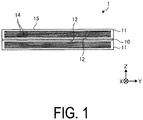
- a joined body 1 formed using the resistance fusing circuit 10 will be described with reference to FIG. 1 .
- FIG. 1 is a cross-sectional view schematically illustrating a joined body according to the first embodiment.
- the joined body 1 is configured to include the resistance fusing circuit 10 and two of the members 11 to be joined provided to both sides of the resistance fusing circuit 10 with the resistance fusing circuit 10 interposed therebetween.
- a thickness direction of the resistance fusing circuit 10 and the members 11 to be joined is defined as a Z direction
- a predetermined direction orthogonal to the thickness direction is defined as an X direction
- a direction orthogonal to the Z direction and the X direction is defined as a Y direction.
- the resistance fusing circuit 10 is a circuit of a thin film that extends along fusing surfaces 12 of the members 11 to be joined.
- the members 11 to be joined are each, for example, a composite material in which carbon fiber 14 is impregnated with a thermoplastic resin 15, i.e., a so-called carbon fiber reinforced thermoplastic (CFRTP).
- CFRTP carbon fiber reinforced thermoplastic
- the member used may be any member as long as the member contains a resin that melts by being heated, and is not particularly limited.
- the present invention may be applied to members to be joined containing a thermosetting resin, or may be applied to a composite material obtained by impregnating reinforcing fibers such as carbon fibers with a thermosetting resin, for example.
- the heating circuit for joining is a heating circuit used to thermally cure the members to be joined. That is, the heating circuit for joining may join the members 11 to be joined by heating and thermally curing the members to be joined (composite materials) in a semicured state.
- the members to be joined containing a thermosetting resin may be adhesive sheets composed of a thermosetting resin to be disposed between members.
- the resistance fusing circuit 10 is disposed between the fusing surfaces 12 of the two members 11 to be joined, thereby superimposing the members 11 to be joined and the resistance fusing circuit 10 in the Z direction. Subsequently, the resistance fusing circuit 10 is energized, causing the resistance fusing circuit 10 to generate heat. When the resistance fusing circuit 10 generates heat, the fusing surfaces 12 of the members 11 to be joined melt and, as a result, the members 11 to be joined are integrated with the resistance fusing circuit 10. Then, the members 11 to be joined are joined by cooling to form the joined body 1.
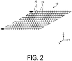
- FIG. 2 is a schematic diagram of the resistance fusing circuit according to the first embodiment.
- the resistance fusing circuit 10 includes a heating wire 21 and a plurality of projections 22 projecting from the heating wire.
- the heating wire 21 is a metal wire that generates heat by being energized, and forms a predetermined wire pattern in the XY plane.
- the heating wire 21 forms, for example, a wire pattern that zigzags in the X direction while reciprocating in the Y direction, and is formed into a substantially rectangular shape in the XY plane.
- the wire pattern is not particularly limited.
- a wire diameter of the heating wire 21 is a diameter that is suitable in accordance with melting conditions and the like of the members 11 to be joined and, similarly, an interval between the heating wires 21 adjacent to each other is an interval that is suitable in accordance with the melting conditions and the like of the members 11 to be joined.
- the plurality of projections 22 are formed projecting from the heating wire 21 in a facing direction in which the members 11 to be joined face each other, that is, in the Z direction.
- the projecting direction of the projections 22 in the Z direction is, for example, a direction orthogonal to the fusing surfaces 12 where the members 11 to be joined melt, but need not necessarily be orthogonal, and may be a direction that includes a component in a direction orthogonal to the fusing surfaces 12.
- the projections 22 may have a wedge shape that tapers toward a tip end in the projecting direction, or may have an inverted triangular shape in which a retainer extending toward the tip end in the projecting direction is formed, and is not particularly limited.
- Each length of the projections 22 in the projecting direction is not less than half a layer thickness of a fused layer obtained by the members 11 to be joined being melted.
- the fused layer is a layer obtained by the members 11 to be joined being melted by the resistance fusing circuit 10 and having a thickness in the Z direction, and is, for example, a layer from the fusing surface 12 to the carbon fiber.
- each length in the projecting direction of the projections 22 is short compared to the interval between the projections 22 adjacent to each other on the heating wire 21. In other words, the interval between the projections 22 adjacent to each other on the heating wire 21 is longer than each length of the projections 22 in the projecting direction.
- each length of the plurality of projections 22 in the projecting direction may be the same or may be different.
- the projections 22 may be configured using the same material as that of the heating wire 21, or may be configured using a different material. When a different material is used, the projections 22 use a material having higher thermal conductivity than the heating wire 21. Therefore, when the resistance fusing circuit 10 is energized, the heat generated by the heating wire 21 can be efficiently transferred to the projections 22.
- the resistance fusing circuit 10 may further include a protective film 23 (refer to FIG. 3 ) covering the heating wire 21 and the projections 22.
- a protective film 23 (refer to FIG. 3 ) covering the heating wire 21 and the projections 22.
- the protective film 23 may be a material different from the resin contained in the members 11 to be joined. In this case, the protective film 23 may be used while still in the attached state or the protective film 23 may be peeled off when the resistance fusing circuit 10 is energized.
- the resin contained in the members 11 to be joined is a thermoplastic resin
- the members 11 to be joined are made of a thermoplastic composite and a film-like adhesive composed of a thermosetting resin is used as the protective film 23
- the protective film 23 may be used while still in the attached state, thereby integrating the members 11 to be joined and the protective film 23.
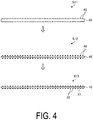
- FIG. 3 to FIG. 5 are explanatory views of an example related to the method of manufacturing the resistance fusing circuit according to the first embodiment.
- FIG. 6 is a plan view schematically illustrating the resistance fusing circuit formed by the method of manufacturing the resistance fusing circuit according to the first embodiment.
- the resistance fusing circuit 10 is formed using a modeling device 40 capable of ejecting conductive ink from an ink-jet head 42 and carrying out three-dimensional modeling.
- the modeling device 40 includes a modeling table 41, the ink-jet head 42, and a guide bar 43 that guides movement of the ink-jet head 42 in a scanning direction.
- Atop surface of the modeling table 41 facing the ink-jet head 42 is a flat surface, and ink droplets ejected from the ink-jet head 42 are adhered thereto.
- the resistance fusing circuit 10 is formed on the modeling table 41.
- the ink-jet head 42 ejects conductive ink and a resin ink containing a thermoplastic resin while being guided in the scanning direction by the guide bar 43.
- the ink-jet head 42 ejects the conductive ink and the resin ink to form a unit layer and layer the unit layers in the Z direction, and forms the resistance fusing circuit 10.
- the resistance fusing circuit 10 is formed using the above-described modeling device 40.
- the modeling device 40 uses unit layer data, which is data obtained by dividing the resistance fusing circuit 10 with the protective film 23 attached on a per unit layer basis in the Z direction.
- the modeling device 40 executes a modeling step of ejecting the conductive ink and the resin ink from the ink-jet head 42 onto the modeling table 41, and layering a plurality of the unit layers in order from a lower layer, thereby forming the resistance fusing circuit 10 composed of the plurality of projections 22 and the protective film 23.
- the heating wire 21 and the plurality of projections 22 are formed using the conductive ink
- the plurality of projections 22 may be formed by arranging the heating wire 21 prepared in advance on the modeling table 41 and ejecting the conductive ink onto this heating wire 21.
- the plurality of projections 22 thus formed may be made of a material having different physical properties from those of the heating wire 21.
- the physical properties of the projections 22 include a high coefficient of thermal conductivity compared to that of the heating wire 21, a high hardness compared to that of the heating wire 21, a high electrical conductivity compared to that of the heating wire 21, and the like.
- etching is performed to form the resistance fusing circuit 10.
- a resist 46 is applied to a base material 45, which is in a state before becoming the resistance fusing circuit 10, at positions where the plurality of projections 22 are to be formed (step S11: resist applying step).
- the base material 45 with the resist 46 applied thereto is subjected to an etching process (step S12: etching step).
- etching step wet etching using an etching solution may be performed, or dry etching using an etching gas may be performed, and the etching is not particularly limited.
- the resist 46 applied to the base material 45 after etching is removed (step S13: resist removal step) to form the resistance fusing circuit 10.
- the resistance fusing circuit 10 is formed using a pair of punch rollers 51.
- the pair of punch rollers 51 execute a punching process of punching a groove for forming the resistance fusing circuit 10 into a base material 48, which is in a state before becoming the resistance fusing circuit 10.
- the base material 48 with the groove punched therein by the pair of punch rollers 51 is, as an example, as illustrated in FIG. 6 , and is divided into a portion constituting the resistance fusing circuit 10 and a pair of areas 48a and 48b provided to both sides of the resistance fusing circuit 10 with the resistance fusing circuit 10 interposed therebetween and to be peeled from the resistance fusing circuit 10.
- a cutout portion for cutting out the heating wire 21 is formed in the base material 48, while a cutout portion is not formed at positions where the projections 22 are to be formed (non-cutout portion).
- the area 48a is guided toward a front surface side (upper side in FIG. 6 ) of the base material 48, and the area 48b is guided toward a back surface side (lower side in FIG. 6 ) of the base material 48, by a pair of guide rollers 52 provided on a downstream side in a transport direction.
- the area 48a that passes through the guide rollers 52 is transported by a transport roller 53 provided on the downstream side in the transport direction, and is thereby peeled from the base material 48.
- the area 48b that passes through the guide rollers 52 is transported by a transport roller 54 provided on the downstream side in the transport direction, and is thereby peeled from the base material 48.
- the pair of areas 48a and 48b are peeled from the base material 48, thereby forming the resistance fusing circuit 10.
- the heating wire 21 is separated from the base material 48, the non-cutout portion is torn away, thereby causing the projections 22 to project.
- the projections 22 serve as resistors against the members 11 to be joined thus melted, and thus the resistance fusing circuit 10 is less likely to flow, making it possible to suppress the occurrence of a short-circuit caused by contact between circuits. Further, because the projections 22 cut into the melted members 11 to be joined, a fusing strength (bonding strength) between the members 11 to be joined can be improved.
- each length of the projections 22 is set to a length not less than half the layer thickness of the fused layer, and thus the projections 22 can suitably cut into the fused layer, making it possible to suitably suppress the flow of the resistance fusing circuit 10 and suitably fuse the members 11 to be joined.
- the projections 22 are made using a material having high thermal conductivity compared to the heating wire 21, making it possible to appropriately melt the members 11 to be joined that come into contact with the projections 22.
- the interval between the projections 22 adjacent to each other is made longer than each length of the projections 22 in the projecting direction, even if the projections 22 are inclined, making it possible to suppress contact between the adjacent projections 22 and therefore the occurrence of a short-circuit caused by contact between the projections 22.
- the heating wire 21 and the projections 22 can be handled in a protected state, and therefore damage to the projections 22 can be alleviated.
- the heating wire 21 and the plurality of projections 22 are formed by the conductive ink ejected from the ink-jet head 42, making it possible to easily form the resistance fusing circuit 10.
- the resistance fusing circuit 10 is formed by etching, making it possible to form the shapes of the heating wire 21 and the plurality of projections 22 with high accuracy.
- the groove (cutout portion) is formed in the base material 48 by the punch roller 51 and the heating wire 21 is separated from the base material 48, making it possible to cause the plurality of projections 22 to project, and thus easily form the resistance fusing circuit 10.
- FIG. 7 is a schematic view of the resistance fusing circuit according to the second embodiment.
- the resistance fusing circuit 60 of the second embodiment includes a heating band 61 and an electrically conductive member 62.
- the heating band 61 is formed in a sheet shape extending in the lengthwise direction, and is formed in a three-dimensional shape by being twisted with the lengthwise direction serving as an axial direction.
- the electrically conductive member 62 connects end portions of the heating band 61, forming a series or parallel circuit from a plurality of the heating bands 61. Note that, in FIG. 7 , the plurality of heating bands 61 are connected by the electrically conductive member 62, forming a series circuit.
- the resistance fusing circuit 60 illustrated in FIG. 7 is manufactured, as an example, the resistance fusing circuit 60 is formed by cutting the heating band 61 having a sheet shape while twisting the heating band 61 with the lengthwise direction serving as the axial direction, arranging side-by-side a plurality of the heating bands 61 thus cut and having a spiral shape, and connecting the heating bands 62 by the electrically conductive members 62.
- the heating band 61 by twisting the heating band 61, it is possible to impart the heating band 61 with a three-dimensional shape.
- the heating band 61 having a three-dimensional shape makes flow less likely with respect to the melted members 11 to be joined, making it possible to suppress the occurrence of a short-circuit caused by contact between circuits. Further, the heating band 61 having a three-dimensional shape cuts into the melted members 11 to be joined, making it possible to improve the fusing strength between the members 11 to be joined.
- FIG. 8 is an explanatory view related to the joining method using the resistance fusing circuit according to the third embodiment.
- the resistance fusing circuit 10 is formed when the members 11 to be joined are joined. Note that, for the resistance fusing circuit 10 used in the joining method according to the third embodiment, the heating wire 21 on which projections 22 are formed and an electrically conductive member 65 are prepared separately. Note that the heating wire 21 and the projections 22 have the same configurations as those of the first embodiment, and thus descriptions thereof will be omitted.
- a plurality of the heating wires 21 are disposed on (the fusing surface 12) of one of the members 11 to be joined.
- the heating wires 21 are arranged with the projecting direction of the projections 22 of the heating wires 21 in the Z direction (step S21).
- the heating wires 21 are connected to each other by the electrically conductive members 65 to form the resistance fusing circuit 10 (step S22: circuit formation step).
- the other member 11 to be joined is arranged on the resistance fusing circuit 10 thus formed, thereby positioning the resistance fusing circuit 10 between the members 11 to be joined (step S23: arrangement step).
- the resistance fusing circuit 10 is energized to melt the members 11 to be joined (step S23: melting step), thereby joining the members 11 to be joined together with the resistance fusing circuit 10.
- the resistance fusing circuit 10 it is possible to form the resistance fusing circuit 10 on the member 11 to be joined, and subsequently join the members 11 to be joined.
- FIG. 9 is an explanatory view related to the joining method using the resistance fusing circuit according to the fourth embodiment.
- the resistance fusing circuit 10 is formed when the members 11 to be joined are joined.
- the heating wire 21 with the projections 22 formed thereon is arranged along a predetermined circuit pattern while being fed out, thereby forming the resistance fusing circuit 10. Note that the heating wire 21 and the projections 22 have the same configurations as those of the first embodiment, and thus descriptions thereof will be omitted.
- a feeding unit 70 configured to feed the heating wire 21, and a pressing roller 71 configured to press the heating wire 21 fed out from the feeding unit 70 onto (the fusing surface 12 of) one of the members 11 to be joined are used.
- a heater 72 is provided to the feeding unit 70, and the heating wire 21 and the projections 22 thus fed are heated by the heater 72.
- the pressing roller 71 is in rolling contact with (the fusing surface 12 of) one of the members 11 to be joined and draws the heating wire 21 and the projections 22 fed out from the feeding unit 70 between the pressing roller 71 and the member 11 to be joined. Then, the pressing roller 71 presses the heating wire 21 and the projections 22 thus drawn against the member 11 to be joined. At this time, a material that does not affect the projecting shape of the projections 22 is used for an outer circumferential surface of the pressing roller 71.
- the heating wire 21 on which the projections 22 are formed is heated and fed out from the above-described feeding unit 70, the heating wire 21 thus fed advances toward the area between the pressing roller 71 and the member 11 to be joined. Then, the heated wire 21 and the projections 22 are pressed against the member 11 to be joined by the pressing roller 71, thereby causing the projections 22 to cut into the member 11 to be joined. Then, the feeding unit 70 arranges the heating wire 21 along a predetermined circuit pattern while feeding the heating wire 21, thereby forming the resistance fusing circuit 10 (circuit formation step).
- the other member 11 to be joined is arranged on the resistance fusing circuit 10 thus formed, thereby positioning the resistance fusing circuit 10 between the members 11 to be joined (arrangement step). Then, the resistance fusing circuit 10 is energized to melt the members 11 to be joined (melting step), thereby joining the members 11 to be joined together with the resistance fusing circuit 10.
- the heating wire 21 is arranged on the member 11 to be joined while heating the heating wire 21 and the projections 22, making it possible for the projections 22 to appropriately cut into the members 11 to be joined. Therefore, the resistance fusing circuit 10 formed on the member 11 to be joined can appropriately join the members 11 to be joined.
- FIG. 10 is an explanatory view related to a joining method using the resistance fusing circuit according to the fifth embodiment.
- the resistance fusing circuit 10 is formed when the members 11 to be joined are joined.
- the heating wire 21 is arranged along a predetermined circuit pattern while being fed out, and the projections 22 are arranged on the heating wire 21 thus arranged, thereby forming the resistance fusing circuit 10.
- the heating wire 21 and the projections 22 have the same configurations as those of the first embodiment, and thus descriptions thereof will be omitted.
- a feeding unit 80 configured to feed out the heating wire 21, an injection unit 81 configured to inject the projections 22, and a pressing roller 82 configured to press the heating wire 21 fed out from the feeding unit 80 onto (the fusing surface 12 of) one of the members 11 to be joined are used.
- the feeding unit 80 feeds out the heating wire 21 between the pressing roller 82 and the member 11 to be joined.
- the injection unit 81 continuously injects the projections 22 toward the pressing roller 82 that is rotating. Therefore, the projections 22 injected from the injection unit 81 are arranged at a predetermined interval in a circumferential direction on an outer circumferential surface of the pressing roller 82.
- a heater 83 is provided to the pressing roller 82, and the projections 22 side by side on the outer circumferential surface are heated by the heater 83.
- the pressing roller 82 is in rolling contact with (the fusing surface 12 of) one of the members 11 to be joined and, on the member 11 to be joined, the projections 22 thus heated are arranged on the heating wire 21 taken in between the pressing roller 82 and the member 11 to be joined. At this time, a material that does not affect the projecting shape of the projections 22 is used for the outer circumferential surface of the pressing roller 82.
- the heating wire 21 when the heating wire 21 is fed out from the above-described feeding unit 80, the heating wire 21 thus fed advances toward the area between the pressing roller 82 and the member 11 to be joined.
- the projections 22 when the projections 22 are injected from the injection unit 81, the projections 22 thus injected pierce the outer circumferential surface of the pressing roller 82. Then, the heating wire 21 is pressed against the member 11 to be joined by the pressing roller 82, and the projections 22 heated by the heater 83 are arranged on the heating wire 21 by the pressing roller 82 and cut into the member 11 to be joined. Then, while feeding out the heating wire 21, the feeding unit 80 arranges the heating wire 21 along a predetermined circuit pattern (heating wire arrangement step).
- the injection unit 81 and the pressing roller 82 arrange the projections 22 on the heating wire 21, thereby forming the resistance fusing circuit 10 (circuit formation step).
- the other member 11 to be joined is arranged on the resistance fusing circuit 10 thus formed, thereby positioning the resistance fusing circuit 10 between the members 11 to be joined (arrangement step).
- the resistance fusing circuit 10 is energized to melt the members 11 to be joined (melting step), thereby joining the members 11 to be joined together with the resistance fusing circuit 10.
- the resistance fusing circuit 10 is formed on the member 11 to be joined while heating the projections 22, making it possible for the projections 22 to appropriately cut into the members 11 to be joined. Therefore, the resistance fusing circuit 10 formed on the member 11 to be joined can appropriately join the members 11 to be joined.
- FIG. 11 is an explanatory view related to the joining method using the resistance fusing circuit according to the sixth embodiment.
- the resistance fusing circuit 10 is formed when the members 11 to be joined are joined.
- the heating wire 21 is arranged along a predetermined circuit pattern while being fed out, and the projections 22 are arranged on the heating wire 21 thus arranged, thereby forming the resistance fusing circuit 10.
- the heating wire 21 and the projections 22 have the same configurations as those of the first embodiment, and thus descriptions thereof will be omitted.
- a feeding unit 90 configured to feed out the heating wire 21, an injection unit 91 configured to inject the projections 22, and a pressing roller 92 configured to press the heating wire 21 fed out from the feeding unit 90 onto (the fusing surface 12 of) one of the members 11 to be joined are used.
- the feeding unit 90 feeds out the heating wire 21 between the pressing roller 92 and the member 11 to be joined.
- the injection unit 91 injects the projections 22 toward the heating wire 21 arranged on the member 11 to be joined.
- a heater 93 is provided to the injection unit 91, and the projections 22 thus injected are heated by the heater 93. Therefore, the projections 22 thus injected from the injection unit 91 and heated are arranged on the heating wire 21 and pierced into the member 11 to be joined.
- the pressing roller 92 is in rolling contact with (the fusing surface 12 of) one of the members 11 to be joined, and the heating wire 21 taken in between the pressing roller 82 and the member 11 to be joined is pressed onto the member 11 to be joined.
- the heating wire 21 when the heating wire 21 is fed out from the above-described feeding unit 90, the heating wire 21 thus fed advances toward the area between the pressing roller 92 and the member 11 to be joined. Then, the heating wire 21 is pressed against the member 11 to be joined by the pressing roller 92, and thus arranged on the member 11 to be joined. Then, while feeding out the heating wire 21, the feeding unit 90 arranges the heating wire 21 along a predetermined circuit pattern (heating wire arrangement step). Next, when the projections 22 are injected from the injection unit 91 to the heating wire on the member 11 to be joined, the projections 22 thus injected are arranged on the heating wire 21 and cut into the member 11 to be joined, thereby forming the resistance fusing circuit 10 (circuit formation step).
- the other member 11 to be joined is arranged on the resistance fusing circuit 10 thus formed, thereby positioning the resistance fusing circuit 10 between the members 11 to be joined (arrangement step). Then, the resistance fusing circuit 10 is energized to melt the members 11 to be joined (melting step), thereby joining the members 11 to be joined together with the resistance fusing circuit 10.
- the resistance fusing circuit 10 is formed on the member 11 to be joined while heating the projections 22, making it possible for the projections 22 to appropriately cut into the members 11 to be joined. Therefore, the resistance fusing circuit 10 formed on the member 11 to be joined can appropriately join the members 11 to be joined.
- FIG. 12 is an explanatory view related to the joining method using the resistance fusing circuit according to the seventh embodiment.
- the resistance fusing circuit 10 is formed when the members 11 to be joined are joined.
- a conductive coating conductive material
- a conductive coating is used to draw a heating wire 101 having a predetermined circuit pattern
- a conductive coating is used to draw the projections 102 on the heating wire 101 thus drawn to form a resistance fusing circuit 100.
- the heating wire 101 is formed using, for example, a plating spray 105 that sprays the conductive coating, and is formed by a predetermined circuit pattern being drawn on the member 11 to be joined at a predetermined thickness using the conductive coating sprayed from the plating spray 105.
- the projections 102 are formed using a plating spray 106 that sprays a conductive coating, and is formed by being drawn in layers on the heating wire 101 of the member 11 to be joined using the conductive coating sprayed from the plating spray 106. Therefore, a first area having a thin thickness in the Z direction (facing direction) and a second area having a thick thickness compared to that of the first area are formed, and the second area is formed as the projections 22.
- the conductive coating is sprayed onto the member 11 to be joined using the plating spray 105 to form the heating wire 101 having a thickness of the first area and a circuit pattern. Subsequently, the conductive coating is sprayed onto the heating wire 101 formed on the member 11 to be joined using the plating spray 106, and a second area having a thickness greater than that of the heating wire 101 is formed as the projections 102 to form the resistance fusing circuit 100 (circuit formation step). Next, the other member 11 to be joined is arranged on the resistance fusing circuit 100 thus formed, thereby positioning the resistance fusing circuit 100 between the members 11 to be joined (arrangement step). Then, the resistance fusing circuit 100 is energized to melt the members 11 to be joined (melting step), thereby joining the members 11 to be joined together with the resistance fusing circuit 100.
- the thickness of the conductive material is increased, thereby making it possible to form the plurality of projections 102. Further, the conductive material is adhered to form the plurality of projections 102 on the heating wire 101, thereby making it possible for the resistance fusing circuit 100 formed on the member 11 to be joined to appropriately join the members 11 to be joined.
- one spray may be used to form the heating wire 101 and the projections 102. That is, one spray may be used to form the first area and the second area while varying the thickness of the conductive coating that adheres to the member 11 to be joined, thereby forming the heating wire 101 on which a plurality of projections 102 are formed.
Landscapes
- Engineering & Computer Science (AREA)
- Mechanical Engineering (AREA)
- Manufacturing & Machinery (AREA)
- Chemical & Material Sciences (AREA)
- Materials Engineering (AREA)
- Composite Materials (AREA)
- Lining Or Joining Of Plastics Or The Like (AREA)
- Resistance Heating (AREA)
- Surface Heating Bodies (AREA)
Applications Claiming Priority (2)
| Application Number | Priority Date | Filing Date | Title |
|---|---|---|---|
| JP2018173029A JP7171332B2 (ja) | 2018-09-14 | 2018-09-14 | 接合用発熱回路、接合体、接合用発熱回路の製造方法及び接合方法 |
| PCT/JP2019/028305 WO2020054215A1 (ja) | 2018-09-14 | 2019-07-18 | 接合用発熱回路、接合体、接合用発熱回路の製造方法及び接合方法 |
Publications (2)
| Publication Number | Publication Date |
|---|---|
| EP3836751A1 true EP3836751A1 (de) | 2021-06-16 |
| EP3836751A4 EP3836751A4 (de) | 2021-10-13 |
Family
ID=69777115
Family Applications (1)
| Application Number | Title | Priority Date | Filing Date |
|---|---|---|---|
| EP19860700.4A Withdrawn EP3836751A4 (de) | 2018-09-14 | 2019-07-18 | Verbindungsheizkreis, verbindungsstück, verfahren zur herstellung eines verbindungsheizkreises und verbindungsverfahren |
Country Status (4)
| Country | Link |
|---|---|
| US (1) | US20210331423A1 (de) |
| EP (1) | EP3836751A4 (de) |
| JP (1) | JP7171332B2 (de) |
| WO (1) | WO2020054215A1 (de) |
Families Citing this family (1)
| Publication number | Priority date | Publication date | Assignee | Title |
|---|---|---|---|---|
| JP2023008163A (ja) * | 2021-07-05 | 2023-01-19 | 豊田合成株式会社 | ワイヤー回路の形成方法 |
Family Cites Families (11)
| Publication number | Priority date | Publication date | Assignee | Title |
|---|---|---|---|---|
| DE4441681A1 (de) * | 1994-11-23 | 1996-05-30 | Teroson Gmbh | Verfahren zum Verbinden von Kunststoff-Formteilen |
| FR2742691B1 (fr) * | 1995-12-22 | 1998-01-23 | Etex De Rech Tech Soc | Element de raccord thermoplastique pour un assemblage de pieces par soudage selon une surface de jonction ouverte |
| JPH1016061A (ja) * | 1996-06-27 | 1998-01-20 | Tohoku Munekata Kk | 熱可塑性合成樹脂で成形された成形品を熱融着する方法及びこの方法に用いられる発熱体 |
| JP2933310B1 (ja) * | 1998-04-20 | 1999-08-09 | 東北ムネカタ株式会社 | 熱可塑性樹脂成形品の熱溶着に際して用いられる発熱体 |
| IL126851A (en) * | 1998-11-02 | 2002-02-10 | Plasson Ltd | Fusion bonding method and assembly produced in accordance with such method |
| JP2002046185A (ja) * | 2000-08-04 | 2002-02-12 | Hokuto:Kk | プラスチック材の溶着方法 |
| JP2010216512A (ja) | 2009-03-13 | 2010-09-30 | Onda Seisakusho:Kk | エレクトロフュージョン継手 |
| DE102009047671A1 (de) | 2009-12-08 | 2011-06-09 | Airbus Operations Gmbh | Verfahren zum Anbinden eines Faserverbundbauteils an ein Strukturbauteil eines Luft- und Raumfahrzeuges und eine entsprechende Anordnung |
| JP2012206492A (ja) | 2011-03-30 | 2012-10-25 | Keihin Corp | 樹脂成形品を熱溶着するための発熱体 |
| JP2013129159A (ja) * | 2011-12-22 | 2013-07-04 | Teijin Ltd | 接合体の製造方法 |
| JP6358818B2 (ja) | 2014-03-06 | 2018-07-18 | 学校法人近畿大学 | 繊維強化熱可塑性樹脂部材の融着方法 |
-
2018
- 2018-09-14 JP JP2018173029A patent/JP7171332B2/ja active Active
-
2019
- 2019-07-18 WO PCT/JP2019/028305 patent/WO2020054215A1/ja not_active Ceased
- 2019-07-18 US US17/268,297 patent/US20210331423A1/en not_active Abandoned
- 2019-07-18 EP EP19860700.4A patent/EP3836751A4/de not_active Withdrawn
Also Published As
| Publication number | Publication date |
|---|---|
| JP2020047393A (ja) | 2020-03-26 |
| WO2020054215A1 (ja) | 2020-03-19 |
| US20210331423A1 (en) | 2021-10-28 |
| EP3836751A4 (de) | 2021-10-13 |
| JP7171332B2 (ja) | 2022-11-15 |
Similar Documents
| Publication | Publication Date | Title |
|---|---|---|
| US20210221054A1 (en) | Methods for fiber reinforced additive manufacturing | |
| CN112078056B (zh) | 纤维增强树脂成型材料及其制造方法、连续碳纤维束及其分纤方法 | |
| JP2015519721A (ja) | 層板パケットおよびその製造方法 | |
| JP6575356B2 (ja) | 強化繊維シート製造装置 | |
| US10899076B2 (en) | Three-dimensional printing method, three-dimensional printing apparatus, and three-dimensional modeled object | |
| CN103213283A (zh) | 窄片复合纤维材料压缩制模 | |
| EP2226747A2 (de) | Schaltungsanordnung sowie Verfahren und Vorrichtung zur Erzeugung eines Schaltungsmusters auf einem Substrat | |
| EP3836751A1 (de) | Verbindungsheizkreis, verbindungsstück, verfahren zur herstellung eines verbindungsheizkreises und verbindungsverfahren | |
| CN110574255A (zh) | 用于将片材件连接为叠片组的设备和方法 | |
| CA2827396C (en) | Carbon-fiber-reinforced plastic structure and method for producing same | |
| JP2005327923A (ja) | 導電接合膜貼着方法および導電接合膜貼着装置 | |
| CN110114200A (zh) | 嵌入用薄膜的树脂层的厚度确定方法、带嵌入用薄膜的树脂成型品的制造方法及嵌入用薄膜 | |
| CN110014660B (zh) | 用于制造载具构件的方法、载具构件及具有载具构件的载具 | |
| JP5648466B2 (ja) | 金属箔張積層板の製造方法 | |
| CN111465999A (zh) | 电阻器的制造方法 | |
| JP6026366B2 (ja) | 補強方法及び補強装置 | |
| JP2018076620A (ja) | 繊維束の分割方法及び分割装置、並びに繊維強化樹脂材料の製造方法及び製造装置 | |
| CN111465998B (zh) | 电阻器的制造方法和电阻器 | |
| JP6650616B2 (ja) | 両面金属張積層板の製造方法 | |
| CN107820636B (zh) | 制造电容式电气装置的方法 | |
| JP2013110143A (ja) | 真空積層装置及びこれを用いた絶縁層の形成方法 | |
| CN111655810A (zh) | 构件连接方法和粘接带 | |
| US20230330972A1 (en) | Composite material fusion method | |
| US20200039204A1 (en) | Methods for making 3d parts using composite based additive manufacturing with perforated sheets and parts formed therefrom | |
| US10201960B2 (en) | Lamination device |
Legal Events
| Date | Code | Title | Description |
|---|---|---|---|
| STAA | Information on the status of an ep patent application or granted ep patent |
Free format text: STATUS: THE INTERNATIONAL PUBLICATION HAS BEEN MADE |
|
| PUAI | Public reference made under article 153(3) epc to a published international application that has entered the european phase |
Free format text: ORIGINAL CODE: 0009012 |
|
| STAA | Information on the status of an ep patent application or granted ep patent |
Free format text: STATUS: REQUEST FOR EXAMINATION WAS MADE |
|
| 17P | Request for examination filed |
Effective date: 20210210 |
|
| AK | Designated contracting states |
Kind code of ref document: A1 Designated state(s): AL AT BE BG CH CY CZ DE DK EE ES FI FR GB GR HR HU IE IS IT LI LT LU LV MC MK MT NL NO PL PT RO RS SE SI SK SM TR |
|
| A4 | Supplementary search report drawn up and despatched |
Effective date: 20210910 |
|
| RIC1 | Information provided on ipc code assigned before grant |
Ipc: B22F 10/10 20210101ALI20210906BHEP Ipc: B22F 7/08 20060101ALI20210906BHEP Ipc: B22F 7/06 20060101ALI20210906BHEP Ipc: B22F 5/12 20060101ALI20210906BHEP Ipc: B33Y 80/00 20150101ALI20210906BHEP Ipc: B33Y 10/00 20150101ALI20210906BHEP Ipc: B29C 65/34 20060101ALI20210906BHEP Ipc: B29C 64/245 20170101ALI20210906BHEP Ipc: B29C 64/112 20170101ALI20210906BHEP Ipc: H05B 3/34 20060101AFI20210906BHEP |
|
| DAV | Request for validation of the european patent (deleted) | ||
| DAX | Request for extension of the european patent (deleted) | ||
| STAA | Information on the status of an ep patent application or granted ep patent |
Free format text: STATUS: THE APPLICATION HAS BEEN WITHDRAWN |
|
| 18W | Application withdrawn |
Effective date: 20221025 |