EP3837708B1 - Elektrischer schalter - Google Patents
Elektrischer schalter Download PDFInfo
- Publication number
- EP3837708B1 EP3837708B1 EP20753351.4A EP20753351A EP3837708B1 EP 3837708 B1 EP3837708 B1 EP 3837708B1 EP 20753351 A EP20753351 A EP 20753351A EP 3837708 B1 EP3837708 B1 EP 3837708B1
- Authority
- EP
- European Patent Office
- Prior art keywords
- spring frame
- detent
- housing
- electrical switch
- spring
- Prior art date
- Legal status (The legal status is an assumption and is not a legal conclusion. Google has not performed a legal analysis and makes no representation as to the accuracy of the status listed.)
- Active
Links
Images

Classifications
-
- H—ELECTRICITY
- H01—ELECTRIC ELEMENTS
- H01H—ELECTRIC SWITCHES; RELAYS; SELECTORS; EMERGENCY PROTECTIVE DEVICES
- H01H19/00—Switches operated by an operating part which is rotatable about a longitudinal axis thereof and which is acted upon directly by a solid body external to the switch, e.g. by a hand
- H01H19/02—Details
- H01H19/10—Movable parts; Contacts mounted thereon
- H01H19/11—Movable parts; Contacts mounted thereon with indexing means
-
- H—ELECTRICITY
- H01—ELECTRIC ELEMENTS
- H01H—ELECTRIC SWITCHES; RELAYS; SELECTORS; EMERGENCY PROTECTIVE DEVICES
- H01H19/00—Switches operated by an operating part which is rotatable about a longitudinal axis thereof and which is acted upon directly by a solid body external to the switch, e.g. by a hand
- H01H19/02—Details
- H01H19/10—Movable parts; Contacts mounted thereon
- H01H19/11—Movable parts; Contacts mounted thereon with indexing means
- H01H19/115—Movable parts; Contacts mounted thereon with indexing means using molded elastic parts only
-
- H—ELECTRICITY
- H01—ELECTRIC ELEMENTS
- H01H—ELECTRIC SWITCHES; RELAYS; SELECTORS; EMERGENCY PROTECTIVE DEVICES
- H01H19/00—Switches operated by an operating part which is rotatable about a longitudinal axis thereof and which is acted upon directly by a solid body external to the switch, e.g. by a hand
- H01H19/54—Switches operated by an operating part which is rotatable about a longitudinal axis thereof and which is acted upon directly by a solid body external to the switch, e.g. by a hand the operating part having at least five or an unspecified number of operative positions
- H01H19/60—Angularly-movable actuating part carrying no contacts
- H01H19/62—Contacts actuated by radial cams
Definitions
- the invention is based on an electrical switch according to the preamble of patent claim 1.
- Such an electrical switch which can be operated like a rotary switch, can be used in electrical and household appliances such as washing machines, dishwashers, etc.
- the switch in these devices serves as a power and/or program selector.
- Such an electrical switch designed as a rotary switch, has a rotatable actuating element.
- a locking mechanism interacts with the actuating element, allowing the actuating element to be rotated into locking positions.
- the locking mechanism consists of a locking wheel, in particular one with an approximately star-shaped design, and at least one locking element that exerts an elastic force and interacts with the locking wheel.
- the locking element consists of a compression spring and a ball and/or a sleeve that engages with the locking wheel.
- Such a locking mechanism therefore comprises a large number of individual parts that are expensive to manufacture and assemble.
- the locking element in the switch often has to be greased before being inserted, which incurs additional costs and permanently contaminates the assembly areas.
- the invention is based on the object of further developing the electrical switch in such a way that the locking mechanism is simpler and more cost-effective.
- the locking element consists of a spring frame, with at least one cam engaging the locking wheel being arranged on the spring frame.
- the spring frame advantageously achieves cost savings in material and/or assembly effort. Further embodiments of the invention are the subject of the dependent claims.
- two cams each engaging the ratchet wheel, can be arranged opposite each other on the spring frame.
- a spring frame not according to the invention can be designed to be closed in a manner that is simple to manufacture. Furthermore, the spring frame can be mounted floatingly in the housing in a manner that is simple to assemble. The cam can expediently be integrated into the spring frame.
- the spring frame is not designed to be closed. Furthermore, two webs are arranged on the spring frame, approximately perpendicular to the spring frame. These webs can also deflect laterally when the shaft rotates, so that forces occurring between the cam and the ratchet wheel are absorbed by the resilient webs. This effectively prevents the spring frame from twisting in an undefined manner.
- the spring frame can be manufactured cost-effectively from plastic, particularly from a thermoplastic.
- the spring frame can expediently operate in the linear-elastic range of the material.
- the housing may also be advantageous for the housing to be made of plastic, particularly from a thermoplastic. In this case, the spring frame can be integrated into the housing in an even more cost-effective manner. The spring frame can be injected into the housing during production.
- the locking mechanism is improved in that the spring assembly is replaced by a closed spring frame, preferably made of plastic.
- the spring operates in the linear-elastic range of the material.
- the cam contour, which engages the spring is adapted to the friction pair of the spring.
- the advantages achieved by the invention are, in particular, that an exact and/or reproducible haptic can be generated for the electrical switch for a given switching function. Due to the special shape of the spring frame, it is self-centering, in particular due to the floating bearing in the housing, which reduces the influence of individual part tolerances. Likewise, the optimized friction pairing between the cam on the spring frame and the ratchet wheel eliminates the need for greasing. With the same force and/or ratchet torque ratio, the previously used number of two spring sleeves is reduced to a single spring frame in the form of a plastic spring, which results in cost savings in material and/or assembly effort.
- the closed design of the spring frame allows, depending on the switching task, either one or both cams to engage with the switching shaft. In particular, the invention allows for smaller switching angles than previously possible.
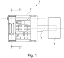
- Fig. 1 1 shows a closer look at an electrical switch 1 not according to the invention, designed as a rotary switch.
- the switch 1 has a housing 2 from which a shaft 3 protrudes.
- the shaft 3 interacts with a contact system located in the housing 2, not shown in detail, to switch the switch 1.
- An actuating element 4, which can be rotated by the user, is arranged on the shaft 3, so that the contact system can be switched into its switching positions by means of the actuating element 4.
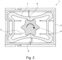
- a locking mechanism 5 interacts with the actuating member 4 in such a way that the actuating member 4 can be rotated into locking positions, the locking positions corresponding to the switching positions of the contact system correspond.
- the locking mechanism 5 consists of a ratchet wheel 6, in particular of an approximately star-shaped design, and at least one locking member 7 which exerts an elastic force and interacts with the ratchet wheel 6.
- the locking member 7 in this case consists of a spring frame. At least one cam 8 which engages in the ratchet wheel 6 is arranged on the spring frame 7.
- two cams 8, 8' each engaging in the ratchet wheel 6, are arranged opposite one another on the spring frame 7, so that the elastic ratchet force exerted by the spring frame 7 acts approximately symmetrically on the ratchet wheel 6.
- Ratchet wheels 6 are arranged, each of which interacts with a spring frame 7 as a locking mechanism 5.
- the spring frame 7 is made of plastic, in particular a thermoplastic.
- the spring frame 7 is operated in the linear-elastic range of the material.
- the housing 2 can also be made of plastic, in particular a thermoplastic.
- the base 2", the cover 2', the spring frame 7, and also the shaft 3 with ratchet wheel 6 and switching cam 9 can be manufactured by injection molding.
- the cam 8, 8' can be integrated into the spring frame 7 by injection molding during the production of the spring frame 7.
- the spring frame 7 is mounted in a floating manner in the housing 2.
- the spring frame 7 can also be integrated in the housing 2, in particular in the base 2", by injecting the spring frame 7 into the housing 2 by means of injection molding during the manufacture of the housing 2.
- Such an electrical switch 1 can be used not only as a rotary switch in household appliances, such as washing machines or dishwashers, but also in other electrical devices, such as power tools.
Landscapes
- Rotary Switch, Piano Key Switch, And Lever Switch (AREA)
Description
- Die Erfindung geht aus von einem elektrischen Schalter nach dem Oberbegriff des Patentanspruchs 1.
- Ein solcher, in der Art eines Drehschalters betätigbarer elektrischer Schalter kann in Elektro- sowie Hausgeräten, wie Waschmaschinen, Geschirrspülmaschinen o. dgl., eingesetzt sein. Beispielsweise dient der Schalter in diesen Geräten als Netz- und/oder Programmwahlschalter.
- Ein derartiger als Drehschalter ausgebildeter elektrischer Schalter besitzt ein drehbares Betätigungsorgan. Mit dem Betätigungsorgan wirkt eine Verrastung zusammen, so dass das Betätigungsorgan in Raststellungen drehbar ist. Die Verrastung besteht aus einem, insbesondere in etwa sternförmig ausgestalteten, Rastrad sowie wenigstens einem eine elastische Kraft ausübenden, mit dem Rastrad zusammenwirkenden Rastglied. Herkömmlicherweise besteht das Rastglied aus einer Druckfeder sowie einer Kugel und/oder einer Hülse, welche in das Rastrad eingreift. Eine derartige Verrastung umfasst somit eine größere Anzahl von Einzelteilen, die in der Herstellung sowie in der Montage teuer sind. Darüber hinaus muss das Rastglied im Schalter oft gefettet eingesetzt werden, was zusätzliche Kosten verursacht und die Montageplätze dauerhaft verschmutzt.
- Druckschriftlicher Stand der Technik im vorliegenden technischen Gebiet ist in den Dokumenten
US 5 589 671 A ,US 3 196 237 A ,DE 20 2008 002 959 U1 , -
DE 26 42 887 A1 undDE 10 2007 013 383 B3 offenbart. - Der Erfindung liegt die Aufgabe zugrunde, den elektrischen Schalter derart weiterzuentwickeln, dass die Verrastung einfacher und kostengünstiger ausgestaltet ist.
- Diese Aufgabe wird bei einem gattungsgemäßen elektrischen Schalter durch die kennzeichnenden Merkmale des Anspruchs 1 gelöst.
- Beim erfindungsgemäßen elektrischen Schalter besteht das Rastglied aus einem Federrahmen, wobei wenigstens ein in das Rastrad eingreifender Nocken am Federrahmen angeordnet ist. In vorteilhafter Weise wird durch den Federrahmen eine Kosteneinsparung beim Material und/oder beim Montageaufwand erzielt. Weitere Ausgestaltungen der Erfindung sind Gegenstand der Unteransprüche.
- In weiterer Ausgestaltung kann für den elektrischen Schalter ein Gehäuse vorgesehen sein. Das Rastrad kann in einfacher Art und Weise an einer, mit dem Betätigungsorgan in Wirkverbindung stehender Welle angeordnet sein. Zweckmäßigerweise kann die Welle drehbar im Gehäuse gelagert sein. Des Weiteren kann in üblicher Weise ein elektrisches Kontaktsystem im Gehäuse befindlich sein, wobei insbesondere das Kontaktsystem mittels eines an der Welle angeordneten Schaltnockens in zu den Raststellungen korrespondierenden Schaltstellungen schaltbar ist.
- Zwecks Erzielung einer besonders guten Drehhaptik für die Betätigung des Schalters können zwei, jeweils in das Rastrad eingreifende Nocken einander gegenüberliegend am Federrahmen angeordnet sein. Es kann jedoch auch genügen, lediglich einen einzigen Nocken am Federrahmen anzuordnen.
- Ein nicht erfindungsgemäßer Federrahmen kann in fertigungstechnisch einfacher Art und Weise geschlossen ausgestaltet sein. Des Weiteren kann der Federrahmen in montagetechnisch einfacher Art und Weise schwimmend im Gehäuse gelagert sein. Zweckmäßigerweise kann der Nocken in den Federrahmen integriert ausgebildet sein.
- Erfindungsgemäß ist der Federrahmen nicht geschlossen ausgestaltet. Des Weiteren sind zwei Stege, in etwa senkrecht zum Federrahmen stehend am Federrahmen angeordnet. Diese Stege können bei Drehung der Welle zusätzlich seitlich ausweichen, so dass zwischen dem Nocken und dem Rastrad auftretende Kräfte durch die federnden Stege aufgenommen werden. Dadurch ist wirksam verhindert, dass der Federrahmen sich undefiniert in sich selbst verwindet.
- In kostengünstiger Weise kann der Federrahmen aus Kunststoff, und zwar insbesondere aus einem thermoplastischen Kunststoff, gefertigt sein. Zweckmäßigerweise kann dabei der Federrahmen in dem linear-elastischen Bereich des Werkstoffes betrieben werden. Des Weiteren kann es sich auch anbieten, dass das Gehäuse aus Kunststoff, und zwar insbesondere aus einem thermoplastischen Kunststoff, besteht. Dann kann in weiterhin kostengünstiger Art und Weise der Federrahmen im Gehäuse integriert sein. Und zwar kann der Federrahmen bei der Herstellung des Gehäuses mittels Spritzgießen in das Gehäuse eingespritzt sein.
- Für eine besonders bevorzugte Ausgestaltung der Erfindung ist nachfolgendes festzustellen.
- Für Drehschalter wird oft eine haptische Rückmeldung gefordert. Dies wird meist durch eine Druckfeder in Kombination mit einer Kugel und/oder einer Hülse gelöst, welche in eine Art von Verzahnung oder in eine spezielle Nockenform eingreift. Diese Systeme gestalten sich zum einen komplex in der Montage und sind, bedingt durch die Anzahl der Einzelteile sowie deren Materialien und/oder Herstellung, meist teuer. Darüber hinaus muss dieses System im Schalter oft "gefettet" eingesetzt werden, was zusätzliche Kosten verursacht und die Montageplätze dauerhaft verschmutzt. Diese Federanordnung soll insbesondere für kostensensible Anwendungsfälle durch eine wirtschaftlichere Lösung ersetzt werden.
- Bei der Erfindung ist der Rastmechanismus dahingehend verbessert, dass die Federanordnung durch einen, vorzugsweise aus Kunststoff gefertigten, geschlossenen Federrahmen ersetzt ist. Die Feder wird in dem linear-elastischen Bereich des Werkstoffes betrieben. Weiterhin ist die Nockenkontur, welche in die Feder eingreift, an die Reibpaarung der Feder angepasst. Dadurch sind die erreichten Lebensdauerzyklen verglichen mit dem bisherigen System mindestens ebenbürtig.
- Es ist auch möglich, den Federrahmen durch eine geeignete Werkzeuganlage direkt im Gehäuse zu integrieren. Hierbei ist Bestandteil der Lösung, dass die Feder nicht nur in Ihrer Vorzugsrichtung ein linear-elastisches Verhalten zeigt. Sie ist vielmehr so gestaltet, dass die aus der Nockenbewegung abgeleitete Kraft normal zur Fläche durch zusätzliche federnde Elemente abgefangen werden kann und sich die Feder dadurch nicht undefiniert in sich selbst verwindet. Im vorliegenden Fall ist dies durch eine integrierte Feder mit zwei, senkrecht zur Hauptfeder stehenden Stegen gelöst, welche zusätzlich seitlich ausweichen können. Wie beim Federrahmen auch wird hier eine exakte und/oder reproduzierbare Haptik bei gegebener Schaltfunktion erzeugt.
- Geschaffen ist somit ein verbesserter Rastmechanismus, der insbesondere aus Kunststoff besteht, für die Drehhaptik eines elektrischen Schalters.
- Die mit der Erfindung erzielten Vorteile bestehen insbesondere darin, dass eine exakte und/oder reproduzierbare Haptik bei gegebener Schaltfunktion für den elektrischen Schalter erzeugbar ist. Aufgrund der speziellen Form des Federrahmens ist dieser selbstzentrierend, insbesondere durch die schwimmende Lagerung im Gehäuse, wodurch der Einfluss der Einzelteiltoleranzen verringert ist. Gleichfalls kann durch die optimierte Reibpaarung zwischen dem Nocken am Federrahmen und dem Rastrad auf ein Fetten verzichtet werden. Bei gleichem Kräfte- und/oder Rastmomentenverhältnis ist die bisher eingesetzte Anzahl von zwei Federhülsen auf einen einzigen Federrahmen in der Art einer Kunststofffeder reduziert, was eine Kosteneinsparung in Material und/oder im Montageaufwand zur Folge hat. Mit dem geschlossenen Aufbau des Federrahmens ist es je nach Schaltaufgabe möglich, sowohl nur eine als auch beide Nocken im Eingriff mit der Schaltwelle zu haben. Insbesondere können mit der Erfindung geringere Schaltdrehwinkel als bisher realisiert werden.
- Ausführungsbeispiele der Erfindung mit verschiedenen Weiterbildungen und Ausgestaltungen sind in den Zeichnungen dargestellt und werden im folgenden näher beschrieben. Es zeigen
- Fig. 1
- einen nicht-erfindungsgemäßen elektrischen Schalter in Seitenansicht,
- Fig. 2
- einen Schnitt entlang der Linie 2-2 in
Fig. 1 , - Fig. 3
- eine Explosionsdarstellung des nicht-erfindungsgemäßen Schalters aus
Fig. 1 , - Fig. 4
- einen Schnitt wie in
Fig. 2 für eine weitere Ausführung des Schalters und - Fig. 5
- eine Explosionsdarstellung wie in
Fig. 3 für die weitere Ausführung des Schalters. - In
Fig. 1 ist ein als Drehschalter ausgestalteter nicht-erfindungsgemäßer elektrischer Schalter 1 näher zu sehen. Der Schalter 1 weist ein Gehäuse 2 auf, aus dem eine Welle 3 herausragt. Die Welle 3 wirkt mit einem im Gehäuse 2 befindlichen, nicht näher gezeigten Kontaktsystem zum Schalten des Schalters 1 zusammen. An der Welle 3 ist ein vom Benutzer drehbares Betätigungsorgan 4 angeordnet, so dass das Kontaktsystem mittels des Betätigungsorgans 4 in dessen Schaltstellungen schaltbar ist. - Wie weiter in
Fig. 2 zu sehen ist, wirkt mit dem Betätigungsorgan 4 eine Verrastung 5 derart zusammen, dass das Betätigungsorgan 4 in Raststellungen drehbar ist, wobei die Raststellungen zu den Schaltstellungen des Kontaktsystems korrespondieren. Die Verrastung 5 besteht aus einem, insbesondere in etwa sternförmig ausgestalteten, Rastrad 6 sowie wenigstens einem eine elastische Kraft ausübenden, mit dem Rastrad 6 zusammenwirkenden Rastglied 7. Das Rastglied 7 besteht vorliegend aus einem Federrahmen. Am Federrahmen 7 ist wenigstens ein in das Rastrad 6 eingreifender Nocken 8 angeordnet. Bei der inFig. 2 gezeigten Ausführung des Schalters 1 sind zwei, jeweils in das Rastrad 6 eingreifende Nocken 8, 8' einander gegenüberliegend am Federrahmen 7 angeordnet, so dass die vom Federrahmen 7 ausgeübte elastische Rastkraft in etwa symmetrisch auf das Rastrad 6 einwirkt. - Wie näher in
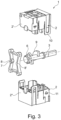
Fig. 3 gezeigt ist, ist das Rastrad 6 an der, mit dem Betätigungsorgan 4 in Wirkverbindung stehenden Welle 3 angeordnet. Die Welle 3 ist drehbar im Gehäuse 1 gelagert. Das Kontaktsystem ist mittels eines an der Welle 3 angeordneten Schaltnockens 9 in zu den Raststellungen korrespondierenden Schaltstellungen schaltbar. Selbstverständlich können auch mehrere Schaltnocken 9 für das Kontaktsystem an der Welle 3 befindlich sein. Der Federrahmen 7 ist geschlossen ausgestaltet und schwimmend im Gehäuse 2 gelagert. Das Gehäuse 2 besteht schließlich aus einem Sockel 2" und einem Deckel 2'. Der Deckel 2' ist mittels Laschen 10 an Rasthaken 11 des Sockels 2" verrastbar. - In
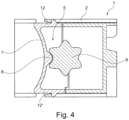
Fig. 4 ist der Schalter 1 gemäß einer weiteren Ausführung gezeigt, wobei hier der Federrahmen 7 nicht geschlossen ausgestaltet ist. Am Federrahmen 7 ist wenigstens ein Steg 12 in etwa senkrecht zum Federrahmen 7 stehend angeordnet. Der Federrahmen 7 ist mit zwei, einander gegenüberliegenden Stegen 12, 12' versehen. Die Stege 12, 12' sind so im Gehäuse 2 angeordnet, dass diese zusätzlich seitlich ausweichen können. Damit zeigt der Federrahmen 7 nicht nur in einer Vorzugsrichtung ein linear-elastisches Verhalten, vielmehr wird die aus der Bewegung des Nockens 8 resultierende Kraft normal zur Fläche des Federrahmens 7 durch die zusätzlichen federnden Stege 12, 12' abgefangen. Somit ist in wirksamer Weise verhindert, dass der Federrahmen 7 sich in undefinierter Weise in sich selbst verwindet. Wie weiter ausFig. 5 hervorgeht sind an der Welle 3 zwei - Rasträder 6 angeordnet, die jeweils mit einem Federrahmen 7 als Verrastung 5 zusammenwirken.
- Der Federrahmen 7 ist aus Kunststoff, und zwar insbesondere aus einem thermoplastischen Kunststoff, gefertigt. Dabei wird der Federrahmen 7 in dem linear-elastischen Bereich des Werkstoffes betrieben. Das Gehäuse 2 kann ebenfalls aus Kunststoff, und zwar insbesondere einem thermoplastischen Kunststoff, bestehen. Somit können der Sockel 2" sowie der Deckel 2' und der Federrahmen 7 sowie auch die Welle 3 mit Rastrad 6 und Schaltnocken 9 mittels Spritzgießen hergestellt werden. Der Nocken 8, 8' kann in den Federrahmen 7 durch Anspritzen bei der Herstellung des Federrahmens 7 integriert sein. Wie bereits erwähnt ist der Federrahmen 7 schwimmend im Gehäuse 2 gelagert.
- In einer Ausführung die nicht zur Erfindung gehört kann der Federrahmen 7 auch im Gehäuse 2, und zwar insbesondere im Sockel 2", integriert sein, indem der Federrahmen 7 bei der Herstellung des Gehäuses 2 mittels Spritzgießen in das Gehäuse 2 eingespritzt ist.
- Die Erfindung ist nicht auf das beschriebene und dargestellte Ausführungsbeispiel beschränkt. Sie umfasst vielmehr auch alle fachmännischen Weiterbildungen im Rahmen der durch die Patentansprüche definierten Erfindung. So kann ein solcher elektrischer Schalter 1 nicht nur als Drehschalter in Hausgeräten, wie Waschmaschinen oder Geschirrspülmaschinen, eingesetzt sein, sondern auch in sonstigen Elektrogeräten, wie Elektrowerkzeugen, Verwendung finden.
-
- 1:
- (elektrischer) Schalter
- 2:
- Gehäuse (von Schalter)
- 2':
- Deckel (von Gehäuse)
- 2":
- Sockel (von Gehäuse)
- 3:
- Welle
- 4:
- Betätigungsorgan
- 5:
- Verrastung
- 6:
- Rastrad
- 7:
- Rastglied / Federrahmen
- 8,8':
- Nocken (an Federrahmen)
- 9:
- Schaltnocken
- 10:
- Lasche
- 11:
- Rasthaken
- 12,12':
- Steg (an Federrahmen)
Claims (5)
- Elektrischer Schalter, insbesondere Drehschalter, mit einem Gehäuse (2), einem drehbaren Betätigungsorgan (4), mit einer derart mit dem Betätigungsorgan (4) zusammenwirkenden Verrastung (5), dass das Betätigungsorgan (4) in Raststellungen drehbar ist, wobei die Verrastung (5) aus einem, insbesondere in etwa sternförmig ausgestalteten, Rastrad (6) sowie wenigstens einem eine elastische Kraft ausübenden, mit dem Rastrad (6) zusammenwirkenden Rastglied (7) besteht, wobei das Rastglied (7) aus einem Federrahmen besteht, und dass wenigstens ein in das Rastrad (6) eingreifender Nocken (8) am Federrahmen (7) angeordnet ist, wobei der Federrahmen (7) nicht geschlossen ausgestaltet ist, und dass zwei Stege (12, 12'), in etwa senkrecht zum Federrahmen (7) stehend am Federrahmen (7) angeordnet sind, dadurch gekennzeichnet , dass der Federrahmen (7) schwimmend in dem Gehäuse (2) gelagert ist.
- Elektrischer Schalter nach Anspruch 1, dadurch gekennzeichnet, dass das Rastrad (6) an einer, mit dem Betätigungsorgan (4) in Wirkverbindung stehenden Welle (3) angeordnet ist, dass vorzugsweise die Welle (3) drehbar im Gehäuse (2) gelagert ist, dass weiter vorzugsweise ein elektrisches Kontaktsystem im Gehäuse (2) befindlich ist, wobei insbesondere das Kontaktsystem mittels eines an der Welle (3) angeordneten Schaltnockens (9) in zu den Raststellungen korrespondierenden Schaltstellungen schaltbar ist.
- Elektrischer Schalter nach Anspruch 1 oder 2, dadurch gekennzeichnet, dass zwei, jeweils in das Rastrad (6) eingreifende Nocken (8, 8') einander gegenüberliegend am Federrahmen (7) angeordnet sind.
- Elektrischer Schalter nach einem der Ansprüche 1 bis 3, dadurch gekennzeichnet, dass der Federrahmen (7) aus Kunststoff, insbesondere aus einem thermoplastischen Kunststoff, gefertigt ist, dass vorzugsweise der Federrahmen (7) in dem linear-elastischen Bereich des Werkstoffes betrieben wird, und dass weiter vorzugsweise der Nocken (8, 8') in den Federrahmen (7) integriert ausgebildet ist.
- Elektrischer Schalter nach einem der Ansprüche 1 bis 4, dadurch gekennzeichnet, dass das Gehäuse (2) aus Kunststoff, insbesondere aus einem thermoplastischen Kunststoff, besteht.
Applications Claiming Priority (2)
| Application Number | Priority Date | Filing Date | Title |
|---|---|---|---|
| DE102019006159.4A DE102019006159A1 (de) | 2019-09-02 | 2019-09-02 | Elektrischer Schalter |
| PCT/EP2020/072194 WO2021043529A1 (de) | 2019-09-02 | 2020-08-06 | Elektrischer schalter |
Publications (2)
| Publication Number | Publication Date |
|---|---|
| EP3837708A1 EP3837708A1 (de) | 2021-06-23 |
| EP3837708B1 true EP3837708B1 (de) | 2025-07-02 |
Family
ID=71994517
Family Applications (1)
| Application Number | Title | Priority Date | Filing Date |
|---|---|---|---|
| EP20753351.4A Active EP3837708B1 (de) | 2019-09-02 | 2020-08-06 | Elektrischer schalter |
Country Status (3)
| Country | Link |
|---|---|
| EP (1) | EP3837708B1 (de) |
| DE (1) | DE102019006159A1 (de) |
| WO (1) | WO2021043529A1 (de) |
Citations (1)
| Publication number | Priority date | Publication date | Assignee | Title |
|---|---|---|---|---|
| DE102007013383B3 (de) * | 2007-03-16 | 2008-09-04 | Preh Gmbh | Bedienelement mit mechanischer Rastung |
Family Cites Families (7)
| Publication number | Priority date | Publication date | Assignee | Title |
|---|---|---|---|---|
| US3196237A (en) * | 1962-07-11 | 1965-07-20 | Ark Les Switch Corp | Rotary switch using plastic cover with integral leaf springs as positioning means |
| US4034178A (en) * | 1975-10-09 | 1977-07-05 | Amp Incorporated | Rotary switch housing having integral flexible detenting walls and rotor mounting structure |
| US4894492A (en) * | 1988-09-01 | 1990-01-16 | Palumbo Nicholas R | Motor control variable speed reversing switch |
| DE4430018A1 (de) * | 1994-08-24 | 1996-02-29 | Siemens Ag | Elektrische Stelleinrichtung |
| US5589671A (en) * | 1995-08-22 | 1996-12-31 | Us Controls Corp. | Rotary switch with spring stabilized contact control rotor |
| DE202008002959U1 (de) * | 2008-03-01 | 2009-07-02 | Gira Giersiepen Gmbh & Co. Kg | Elektrische Installationsvorrichtung, wie Drehschalter oder Drehregler, insbesondere Rastpotentiometer |
| JP2017091603A (ja) * | 2015-11-02 | 2017-05-25 | 株式会社村田製作所 | 回転エンコーダ |
-
2019
- 2019-09-02 DE DE102019006159.4A patent/DE102019006159A1/de active Pending
-
2020
- 2020-08-06 WO PCT/EP2020/072194 patent/WO2021043529A1/de not_active Ceased
- 2020-08-06 EP EP20753351.4A patent/EP3837708B1/de active Active
Patent Citations (1)
| Publication number | Priority date | Publication date | Assignee | Title |
|---|---|---|---|---|
| DE102007013383B3 (de) * | 2007-03-16 | 2008-09-04 | Preh Gmbh | Bedienelement mit mechanischer Rastung |
Also Published As
| Publication number | Publication date |
|---|---|
| DE102019006159A1 (de) | 2021-03-04 |
| EP3837708A1 (de) | 2021-06-23 |
| WO2021043529A1 (de) | 2021-03-11 |
Similar Documents
| Publication | Publication Date | Title |
|---|---|---|
| DE2826721C2 (de) | ||
| EP0609672A2 (de) | Sicherheitsschalter | |
| DE102011087829A1 (de) | Rastvorrichtung für ein rotatorisch oder translatorisch bewegbares Bedienelement | |
| EP3837708B1 (de) | Elektrischer schalter | |
| EP1612103B1 (de) | Spieloptimierte Aufnahme für Schaltstück | |
| WO2011045214A1 (de) | Leistungsschalter, insbesondere für niederspannungen | |
| EP0936643B1 (de) | Drehschaltervorrichtung für elektrische Haushaltsgeräte | |
| DE60030934T2 (de) | Anordnung zur verstärkung des hubs eines betätigungsorgans eines schalters | |
| DE10037142B4 (de) | Elektrisches Schaltelement | |
| DE10025471C2 (de) | Wasserdichter Hebelschalter | |
| EP1482527B1 (de) | Tastenblock | |
| EP1960857A1 (de) | Mehrstufenschalter | |
| EP2972644B1 (de) | Eingabeeinheit für ein druck- und drehbetätigbares bedienelement | |
| EP0337927B1 (de) | Bereichsumschalter, insbesondere für ein elektronisches Zeitrelais | |
| DE4328030C2 (de) | Elektrischer Drehschalter | |
| EP0502394B1 (de) | Kontaktanordnung | |
| DE102024138996B3 (de) | Elektrisches Schaltgerät mit formgefedertem Druckstück | |
| DE29609204U1 (de) | Kraftfahrzeug-Türschloß o.dgl. mit Kunststoff-Gehäuseteil | |
| DE10321857B4 (de) | Elektrischer Schalter | |
| EP1686600A2 (de) | 2-poliger Umschalter | |
| DE102005018144B4 (de) | Elektrische Schalteranordnung | |
| DE102005013471A1 (de) | Verschluß für ein Hausgerät | |
| DE102017203810B4 (de) | Bedieneinrichtung für ein Elektrogerät und Elektrogerät | |
| EP4119848A1 (de) | Bedieneinrichtung eines haushaltsgeräts und haushaltsgerät | |
| DE102009005283B4 (de) | Druck- und drehbetätigbares Bedienelement für ein Kraftfahrzeug |
Legal Events
| Date | Code | Title | Description |
|---|---|---|---|
| STAA | Information on the status of an ep patent application or granted ep patent |
Free format text: STATUS: UNKNOWN |
|
| STAA | Information on the status of an ep patent application or granted ep patent |
Free format text: STATUS: THE INTERNATIONAL PUBLICATION HAS BEEN MADE |
|
| PUAI | Public reference made under article 153(3) epc to a published international application that has entered the european phase |
Free format text: ORIGINAL CODE: 0009012 |
|
| STAA | Information on the status of an ep patent application or granted ep patent |
Free format text: STATUS: REQUEST FOR EXAMINATION WAS MADE |
|
| 17P | Request for examination filed |
Effective date: 20210318 |
|
| AK | Designated contracting states |
Kind code of ref document: A1 Designated state(s): AL AT BE BG CH CY CZ DE DK EE ES FI FR GB GR HR HU IE IS IT LI LT LU LV MC MK MT NL NO PL PT RO RS SE SI SK SM TR |
|
| DAV | Request for validation of the european patent (deleted) | ||
| DAX | Request for extension of the european patent (deleted) | ||
| STAA | Information on the status of an ep patent application or granted ep patent |
Free format text: STATUS: EXAMINATION IS IN PROGRESS |
|
| 17Q | First examination report despatched |
Effective date: 20230714 |
|
| GRAP | Despatch of communication of intention to grant a patent |
Free format text: ORIGINAL CODE: EPIDOSNIGR1 |
|
| STAA | Information on the status of an ep patent application or granted ep patent |
Free format text: STATUS: GRANT OF PATENT IS INTENDED |
|
| INTG | Intention to grant announced |
Effective date: 20250408 |
|
| GRAS | Grant fee paid |
Free format text: ORIGINAL CODE: EPIDOSNIGR3 |
|
| GRAA | (expected) grant |
Free format text: ORIGINAL CODE: 0009210 |
|
| STAA | Information on the status of an ep patent application or granted ep patent |
Free format text: STATUS: THE PATENT HAS BEEN GRANTED |
|
| P01 | Opt-out of the competence of the unified patent court (upc) registered |
Free format text: CASE NUMBER: APP_20195/2025 Effective date: 20250428 |
|
| AK | Designated contracting states |
Kind code of ref document: B1 Designated state(s): AL AT BE BG CH CY CZ DE DK EE ES FI FR GB GR HR HU IE IS IT LI LT LU LV MC MK MT NL NO PL PT RO RS SE SI SK SM TR |
|
| REG | Reference to a national code |
Ref country code: GB Ref legal event code: FG4D Free format text: NOT ENGLISH |
|
| REG | Reference to a national code |
Ref country code: CH Ref legal event code: EP |
|
| REG | Reference to a national code |
Ref country code: DE Ref legal event code: R096 Ref document number: 502020011347 Country of ref document: DE |
|
| REG | Reference to a national code |
Ref country code: IE Ref legal event code: FG4D Free format text: LANGUAGE OF EP DOCUMENT: GERMAN |
|
| PGFP | Annual fee paid to national office [announced via postgrant information from national office to epo] |
Ref country code: GB Payment date: 20250820 Year of fee payment: 6 |
|
| PGFP | Annual fee paid to national office [announced via postgrant information from national office to epo] |
Ref country code: FR Payment date: 20250829 Year of fee payment: 6 |
|
| REG | Reference to a national code |
Ref country code: NL Ref legal event code: MP Effective date: 20250702 |
|
| PG25 | Lapsed in a contracting state [announced via postgrant information from national office to epo] |
Ref country code: PT Free format text: LAPSE BECAUSE OF FAILURE TO SUBMIT A TRANSLATION OF THE DESCRIPTION OR TO PAY THE FEE WITHIN THE PRESCRIBED TIME-LIMIT Effective date: 20251103 |
|
| PG25 | Lapsed in a contracting state [announced via postgrant information from national office to epo] |
Ref country code: NL Free format text: LAPSE BECAUSE OF FAILURE TO SUBMIT A TRANSLATION OF THE DESCRIPTION OR TO PAY THE FEE WITHIN THE PRESCRIBED TIME-LIMIT Effective date: 20250702 |
|
| PG25 | Lapsed in a contracting state [announced via postgrant information from national office to epo] |
Ref country code: IS Free format text: LAPSE BECAUSE OF FAILURE TO SUBMIT A TRANSLATION OF THE DESCRIPTION OR TO PAY THE FEE WITHIN THE PRESCRIBED TIME-LIMIT Effective date: 20251102 |
|
| PGFP | Annual fee paid to national office [announced via postgrant information from national office to epo] |
Ref country code: DE Payment date: 20251028 Year of fee payment: 6 |
|
| PG25 | Lapsed in a contracting state [announced via postgrant information from national office to epo] |
Ref country code: NO Free format text: LAPSE BECAUSE OF FAILURE TO SUBMIT A TRANSLATION OF THE DESCRIPTION OR TO PAY THE FEE WITHIN THE PRESCRIBED TIME-LIMIT Effective date: 20251002 |
|
| REG | Reference to a national code |
Ref country code: LT Ref legal event code: MG9D |
|
| PG25 | Lapsed in a contracting state [announced via postgrant information from national office to epo] |
Ref country code: FI Free format text: LAPSE BECAUSE OF FAILURE TO SUBMIT A TRANSLATION OF THE DESCRIPTION OR TO PAY THE FEE WITHIN THE PRESCRIBED TIME-LIMIT Effective date: 20250702 |
|
| PG25 | Lapsed in a contracting state [announced via postgrant information from national office to epo] |
Ref country code: HR Free format text: LAPSE BECAUSE OF FAILURE TO SUBMIT A TRANSLATION OF THE DESCRIPTION OR TO PAY THE FEE WITHIN THE PRESCRIBED TIME-LIMIT Effective date: 20250702 |
|
| PG25 | Lapsed in a contracting state [announced via postgrant information from national office to epo] |
Ref country code: GR Free format text: LAPSE BECAUSE OF FAILURE TO SUBMIT A TRANSLATION OF THE DESCRIPTION OR TO PAY THE FEE WITHIN THE PRESCRIBED TIME-LIMIT Effective date: 20251003 |
|
| PG25 | Lapsed in a contracting state [announced via postgrant information from national office to epo] |
Ref country code: CZ Free format text: LAPSE BECAUSE OF FAILURE TO SUBMIT A TRANSLATION OF THE DESCRIPTION OR TO PAY THE FEE WITHIN THE PRESCRIBED TIME-LIMIT Effective date: 20250702 Ref country code: SE Free format text: LAPSE BECAUSE OF FAILURE TO SUBMIT A TRANSLATION OF THE DESCRIPTION OR TO PAY THE FEE WITHIN THE PRESCRIBED TIME-LIMIT Effective date: 20250702 |
|
| PG25 | Lapsed in a contracting state [announced via postgrant information from national office to epo] |
Ref country code: LV Free format text: LAPSE BECAUSE OF FAILURE TO SUBMIT A TRANSLATION OF THE DESCRIPTION OR TO PAY THE FEE WITHIN THE PRESCRIBED TIME-LIMIT Effective date: 20250702 |
|
| PG25 | Lapsed in a contracting state [announced via postgrant information from national office to epo] |
Ref country code: PL Free format text: LAPSE BECAUSE OF FAILURE TO SUBMIT A TRANSLATION OF THE DESCRIPTION OR TO PAY THE FEE WITHIN THE PRESCRIBED TIME-LIMIT Effective date: 20250702 Ref country code: BG Free format text: LAPSE BECAUSE OF FAILURE TO SUBMIT A TRANSLATION OF THE DESCRIPTION OR TO PAY THE FEE WITHIN THE PRESCRIBED TIME-LIMIT Effective date: 20250702 |
|
| PG25 | Lapsed in a contracting state [announced via postgrant information from national office to epo] |
Ref country code: RS Free format text: LAPSE BECAUSE OF FAILURE TO SUBMIT A TRANSLATION OF THE DESCRIPTION OR TO PAY THE FEE WITHIN THE PRESCRIBED TIME-LIMIT Effective date: 20251002 |
|
| PG25 | Lapsed in a contracting state [announced via postgrant information from national office to epo] |
Ref country code: ES Free format text: LAPSE BECAUSE OF FAILURE TO SUBMIT A TRANSLATION OF THE DESCRIPTION OR TO PAY THE FEE WITHIN THE PRESCRIBED TIME-LIMIT Effective date: 20250702 |
|
| PG25 | Lapsed in a contracting state [announced via postgrant information from national office to epo] |
Ref country code: RO Free format text: LAPSE BECAUSE OF FAILURE TO SUBMIT A TRANSLATION OF THE DESCRIPTION OR TO PAY THE FEE WITHIN THE PRESCRIBED TIME-LIMIT Effective date: 20250702 |
|
| REG | Reference to a national code |
Ref country code: CH Ref legal event code: H13 Free format text: ST27 STATUS EVENT CODE: U-0-0-H10-H13 (AS PROVIDED BY THE NATIONAL OFFICE) Effective date: 20260324 |
|
| PG25 | Lapsed in a contracting state [announced via postgrant information from national office to epo] |
Ref country code: SM Free format text: LAPSE BECAUSE OF FAILURE TO SUBMIT A TRANSLATION OF THE DESCRIPTION OR TO PAY THE FEE WITHIN THE PRESCRIBED TIME-LIMIT Effective date: 20250702 |
|
| PG25 | Lapsed in a contracting state [announced via postgrant information from national office to epo] |
Ref country code: DK Free format text: LAPSE BECAUSE OF FAILURE TO SUBMIT A TRANSLATION OF THE DESCRIPTION OR TO PAY THE FEE WITHIN THE PRESCRIBED TIME-LIMIT Effective date: 20250702 |
|
| PG25 | Lapsed in a contracting state [announced via postgrant information from national office to epo] |
Ref country code: LU Free format text: LAPSE BECAUSE OF NON-PAYMENT OF DUE FEES Effective date: 20250806 Ref country code: IT Free format text: LAPSE BECAUSE OF FAILURE TO SUBMIT A TRANSLATION OF THE DESCRIPTION OR TO PAY THE FEE WITHIN THE PRESCRIBED TIME-LIMIT Effective date: 20250702 |
|
| PG25 | Lapsed in a contracting state [announced via postgrant information from national office to epo] |
Ref country code: CH Free format text: LAPSE BECAUSE OF NON-PAYMENT OF DUE FEES Effective date: 20250831 |
|
| PG25 | Lapsed in a contracting state [announced via postgrant information from national office to epo] |
Ref country code: EE Free format text: LAPSE BECAUSE OF FAILURE TO SUBMIT A TRANSLATION OF THE DESCRIPTION OR TO PAY THE FEE WITHIN THE PRESCRIBED TIME-LIMIT Effective date: 20250702 Ref country code: SK Free format text: LAPSE BECAUSE OF FAILURE TO SUBMIT A TRANSLATION OF THE DESCRIPTION OR TO PAY THE FEE WITHIN THE PRESCRIBED TIME-LIMIT Effective date: 20250702 |