EP3838455A1 - Système d'outil - Google Patents
Système d'outil Download PDFInfo
- Publication number
- EP3838455A1 EP3838455A1 EP19216972.0A EP19216972A EP3838455A1 EP 3838455 A1 EP3838455 A1 EP 3838455A1 EP 19216972 A EP19216972 A EP 19216972A EP 3838455 A1 EP3838455 A1 EP 3838455A1
- Authority
- EP
- European Patent Office
- Prior art keywords
- tool
- cutting
- tool holder
- side shaft
- longitudinal axis
- Prior art date
- Legal status (The legal status is an assumption and is not a legal conclusion. Google has not performed a legal analysis and makes no representation as to the accuracy of the status listed.)
- Pending
Links
Images




Classifications
-
- B—PERFORMING OPERATIONS; TRANSPORTING
- B23—MACHINE TOOLS; METAL-WORKING NOT OTHERWISE PROVIDED FOR
- B23B—TURNING; BORING
- B23B1/00—Methods for turning or working essentially requiring the use of turning-machines; Use of auxiliary equipment in connection with such methods
-
- B—PERFORMING OPERATIONS; TRANSPORTING
- B23—MACHINE TOOLS; METAL-WORKING NOT OTHERWISE PROVIDED FOR
- B23B—TURNING; BORING
- B23B27/00—Tools for turning or boring machines; Tools of a similar kind in general; Accessories therefor
- B23B27/14—Cutting tools of which the bits or tips or cutting inserts are of special material
- B23B27/16—Cutting tools of which the bits or tips or cutting inserts are of special material with exchangeable cutting bits or cutting inserts, e.g. able to be clamped
- B23B27/1603—Cutting tools of which the bits or tips or cutting inserts are of special material with exchangeable cutting bits or cutting inserts, e.g. able to be clamped with specially shaped plate-like exchangeable cutting inserts, e.g. chip-breaking groove
- B23B27/1611—Cutting tools of which the bits or tips or cutting inserts are of special material with exchangeable cutting bits or cutting inserts, e.g. able to be clamped with specially shaped plate-like exchangeable cutting inserts, e.g. chip-breaking groove characterised by having a special shape
-
- B—PERFORMING OPERATIONS; TRANSPORTING
- B23—MACHINE TOOLS; METAL-WORKING NOT OTHERWISE PROVIDED FOR
- B23B—TURNING; BORING
- B23B27/00—Tools for turning or boring machines; Tools of a similar kind in general; Accessories therefor
- B23B27/14—Cutting tools of which the bits or tips or cutting inserts are of special material
- B23B27/16—Cutting tools of which the bits or tips or cutting inserts are of special material with exchangeable cutting bits or cutting inserts, e.g. able to be clamped
- B23B27/1681—Adjustable position of the plate-like cutting inserts
-
- B—PERFORMING OPERATIONS; TRANSPORTING
- B23—MACHINE TOOLS; METAL-WORKING NOT OTHERWISE PROVIDED FOR
- B23B—TURNING; BORING
- B23B29/00—Holders for non-rotary cutting tools; Boring bars or boring heads; Accessories for tool holders
- B23B29/04—Tool holders for a single cutting tool
- B23B29/12—Special arrangements on tool holders
- B23B29/20—Special arrangements on tool holders for placing same by shanks in sleeves of a turret
- B23B29/205—Special arrangements on tool holders for placing same by shanks in sleeves of a turret the tools being adjustable
-
- B—PERFORMING OPERATIONS; TRANSPORTING
- B23—MACHINE TOOLS; METAL-WORKING NOT OTHERWISE PROVIDED FOR
- B23Q—DETAILS, COMPONENTS, OR ACCESSORIES FOR MACHINE TOOLS, e.g. ARRANGEMENTS FOR COPYING OR CONTROLLING; MACHINE TOOLS IN GENERAL CHARACTERISED BY THE CONSTRUCTION OF PARTICULAR DETAILS OR COMPONENTS; COMBINATIONS OR ASSOCIATIONS OF METAL-WORKING MACHINES, NOT DIRECTED TO A PARTICULAR RESULT
- B23Q5/00—Driving or feeding mechanisms; Control arrangements therefor
- B23Q5/02—Driving main working members
- B23Q5/04—Driving main working members rotary shafts, e.g. working-spindles
- B23Q5/043—Accessories for spindle drives
- B23Q5/048—Speed-changing devices
-
- B—PERFORMING OPERATIONS; TRANSPORTING
- B23—MACHINE TOOLS; METAL-WORKING NOT OTHERWISE PROVIDED FOR
- B23B—TURNING; BORING
- B23B2200/00—Details of cutting inserts
- B23B2200/04—Overall shape
- B23B2200/0423—Irregular
-
- B—PERFORMING OPERATIONS; TRANSPORTING
- B23—MACHINE TOOLS; METAL-WORKING NOT OTHERWISE PROVIDED FOR
- B23B—TURNING; BORING
- B23B2200/00—Details of cutting inserts
- B23B2200/16—Supporting or bottom surfaces
- B23B2200/161—Supporting or bottom surfaces with projections
-
- B—PERFORMING OPERATIONS; TRANSPORTING
- B23—MACHINE TOOLS; METAL-WORKING NOT OTHERWISE PROVIDED FOR
- B23B—TURNING; BORING
- B23B2205/00—Fixation of cutting inserts in holders
- B23B2205/18—Systems for indexing the cutting insert automatically
-
- B—PERFORMING OPERATIONS; TRANSPORTING
- B23—MACHINE TOOLS; METAL-WORKING NOT OTHERWISE PROVIDED FOR
- B23B—TURNING; BORING
- B23B2260/00—Details of constructional elements
- B23B2260/076—Harmonic drive gearboxes, i.e. reduction gearing including wave generator, flex spline and a circular spline
Definitions
- the present invention relates to a tool system for machining, in particular for turning, and a method for machining a workpiece.
- machining operations are required for complete machining of a workpiece, which differ at least with regard to an angle of attack and / or in terms of indexable inserts.
- further processing steps outside of a turning center of the workpiece are often required, such as face milling, longitudinal and transverse drilling, etc.
- Several tool changes may therefore be required for complete machining of a workpiece.
- the tools are arranged on a tool carrier with several tool stations.
- An example of such a tool holder is a tool turret (also called a turret tool holder).
- the tool currently required can be swiveled into an operating position by turning the turret disk.
- the object of the present invention is to overcome the disadvantages of the prior art discussed above.
- the tool system according to the invention creates the possibility of transferring a rotary movement of a driven tool holder to the tool-side shaft in a stepped manner in order to rotationally adjust the insert seat formed on the tool holder for receiving an exchangeable cutting insert.
- the reduction is carried out in such a way that a machine-side speed or an angular movement on the drive side is transferred to the tool-side shaft in a reduced manner.
- a high level of positioning accuracy is achieved through the reduction, because a rotary movement of a drive of the driven tool holder by a certain angle is reduced by the reduction factor and transmitted to the tool-side shaft.
- the gear reduction results in or at least promotes self-locking of the gear.
- a reverse torque flow i.e. from the tool in the direction of the drive, is thus suppressed.
- forces applied to the tool-side shank for example cutting forces, do not lead to undesired rotation.
- a rotary movement transmitted by the machine-side shaft is transmitted to the tool-side shaft with a reduction ratio between 50: 1 to 1000: 1, preferably between 75: 1 and 125: 1, more preferably about 100: 1.
- "About 100: 1" in the particularly preferred embodiment also includes deviations of +/- 10%, that is to say 90: 1 to 110: 1.
- a particularly high positioning accuracy is achieved through the preferably high degree of reduction.
- a reduction of preferably about 100: 1 also offers a good compromise between positioning accuracy and adjustment speed.
- Drives for driven tool holders typically have speeds of 4000 to 5000 rpm. With a reduction of 100: 1, this means speeds on the tool-side shaft of 40 - 50 rpm.
- the gear unit has a reduction ratio of 120: 1.
- a desired whole-number tool-side angle change can be programmed particularly easily: in the example mentioned of a preferred reduction of 120: 1, a machine-side rotation (i.e. 360 ° in degrees) causes a tool-side angle change of 3 ° (360 ° / 120).
- the tool system according to the invention makes it possible, for example, to move a tool arranged on the tool-side shaft, for example a cutting plate, into a different position, that is to say to adjust it.
- Another position can mean, among other things, an alignment of a cutting edge of a cutting insert.
- the same tool can be used for another machining step, which machining step differs from the previously selected setting of the tool with regard to the required cutting edge alignment.
- a change from longitudinal turning to face turning is an example.
- Another position can also mean providing another cutting edge of the cutting insert. This is particularly relevant in the case of cutting inserts which have several, sometimes differently designed, cutting edges.
- the tool system according to the invention for example, only a single place on a tool carrier is required for two or even more processing steps, for which two or even more different tools and thus places on the tool carrier would be required without the tool system according to the invention.
- the tool system according to the invention allows a tool to be used particularly economically, since the same tool can optionally be used for different machining steps.
- the transmission is designed to be free of play, or a play compensation can be provided. It is particularly advantageous if the transmission is designed to be self-locking. This means that a moment impressed on the tool side does not result in a Twisting leads. This is particularly advantageous in order not to lose the original position when changing turret positions, but rather to retain it for a subsequent use. In this context, it is particularly favorable if the transmission of a rotary movement can be coupled on the machine side. When changing a tool location, the original position can be used again after changing a tool location.
- the transmission can preferably be a stress wave transmission (also called wave transmission or sliding wedge transmission, also known as Harmonic Drive® transmission). This type of gear unit is characterized by its particular positioning accuracy and low play.
- the shank on the machine side is designed as a tool holder compatible with DIN 69880 / DIN ISO 10889 - a so-called VDI holder.
- VDI tool holders are designated according to the diameter of the tool holder, for example "VDI 40" for a cylinder diameter of the tool holder of 40 mm.
- the means for transmitting a rotary movement can for example consist of a shaft.
- the means for transmitting a rotary movement comprises an interface for coupling to a drive, which is designed to pick up a rotary movement of a driven tool holder.
- the interface consists of a toothing, for example a polygon toothing, which can be inserted into a corresponding counter-toothing of a tool carrier.
- the interface can be designed such that it can be coupled.
- a longitudinal axis of the machine-side shaft runs essentially parallel to a longitudinal axis of the tool-side shaft and / or of the tool holder.
- the longitudinal axis of the machine-side shaft runs essentially coaxially to the longitudinal axis of the tool-side shaft.
- This cranked arrangement is particularly advantageous for use of the tool system on a so-called star turret, that is to say a tool carrier with a circumferential (radial) arrangement of tool holders.
- the longitudinal axis of the tool holder runs parallel and laterally offset to the longitudinal axis of the tool-side shaft.
- the tool holder is not formed coaxially on the tool-side shaft. This arrangement has the effect that, during the rotary movement of the tool-side shaft, the tool holder executes a pivoting movement along a circular path about the longitudinal axis of the tool-side shaft.
- the longitudinal axis of the tool-side shaft and / or of the tool holder runs inclined to the longitudinal axis of the machine-side shaft. So there is an angular offset between the drive and the output.
- the angle can preferably be a right angle.
- An angled arrangement is particularly advantageous for use of the tool system on a so-called disk turret, that is to say a tool carrier with an end-face (axial) arrangement of the tool holders.
- An insert seat for receiving an exchangeable cutting insert is provided on the tool holder.
- the insert seat is oriented transversely to the tool holder, that is to say transversely to the longitudinal axis of the tool holder.
- the insert seat is preferably oriented essentially perpendicular to the longitudinal axis of the tool holder. In other words, this means that the plane normal of the insert seat runs essentially parallel to the longitudinal axis of the tool holder.
- an insert seat is often not designed as a flat surface. Rather, an insert seat usually has a surface design that is provided on an underside of an insert for receiving it in the insert seat The insert corresponds, so that the insert is also positively fixed in the insert seat.
- This surface design can be in the form of positioning elements, which can, for example, specify a correctly positioned installation of a cutting insert on the insert seat.
- positioning elements can, for example, specify a correctly positioned installation of a cutting insert on the insert seat.
- plane normals pointing in different directions on the surface of an insert seat.
- the reference plane is understood to be that plane to which the predominant action of a clamping force occurs.
- the clamping force is usually generated via a clamping screw or a clamping claw, by means of which clamping force a cutting insert is drawn into the insert seat.
- Orientation of the insert seat “transversely to the tool holder” means that the reference plane of the insert seat runs inclined to the longitudinal axis of the tool holder.
- the insert seat is aligned essentially perpendicular to the longitudinal axis of the tool holder. “Essentially” also includes deviations of several degrees, for example 10 °. However, it is particularly favorable if the insert seat is aligned perpendicular to the longitudinal axis of the tool holder.
- the insert seat is preferably designed to receive a cutting insert for turning.
- an exchangeable cutting insert comprising at least one cutting corner is also attached to the at least one insert seat an upper side designed as a rake face and an underside designed as a contact surface are arranged such that the upper side of the cutting insert extends essentially perpendicular to the longitudinal axis of the tool holder. “Essentially” also includes deviations of several degrees, for example 10 °. However, it is particularly favorable if the top of the cutting insert is aligned perpendicular to the longitudinal axis of the tool holder.
- the cutting plate is also preferably designed as a polygonal cutting plate. In this case, the cutting insert has cutting edges delimited by cutting corners.
- the cutting plate is particularly preferably designed as an essentially triangular plate with three cutting corners that can be used for machining.
- the cutting insert is arranged in such a way that at least one cutting corner and cutting edge sections adjoining it on both sides protrude beyond an outer circumference of the end face of the tool holder. More preferably, the entire outer circumference of the cutting insert protrudes beyond the outer circumference of the tool holder. This means that the cutting insert can in principle be used along its entire circumference.
- the cutting plate can, for example, have several similarly designed cutting edges or differently designed cutting edges can be provided.
- a cutting plate with a basic shape of an equilateral triangle is advantageous with regard to indexing of the cutting plate, which is particularly simple in this case, i.e. further turning of the cutting plate to the next cutting corner, which further turning can take place with the tool system according to the invention. This means that it is not necessary to remove the insert from the insert seat.
- the tool system is designed in such a way that the longitudinal axis of the tool-side shank and thus the axis of rotation of the tool-side shank runs through the cutting corner radius center, if the orientation of the cutting insert changes, a contour of the cutting corner in question is invariant with respect to the rotation.
- a radial distance between the cutting corner and the workpiece remains unchanged when the cutting insert rotates about said axis of rotation.
- the tool system allows, for example, a change in the angle of incidence of a cutting edge in that the rotary movement that can be tapped off by the driven tool holder is transmitted in a reduced manner to the tool-side shaft. This means that the same insert can be used for different Cutting operations are used that require different angles of attack.
- the cutting plate further preferably has at least two cutting edges that differ from one another.
- another cutting edge can be brought into a processing position for a next processing step by transferring the cutting edge from the driven tool holder to the tool holder.
- the tool system makes it possible to adjust the cutting plate in such a way that other cutting edges are brought into position for different machining operations by transferring the rotary movement that can be picked up by the driven tool holder to the tool-side shank.
- the tool system is particularly suitable for turning operations.
- the method for machining a workpiece is, in particular, turning.
- an alignment of a cutting insert is changed via a rotary movement that can be tapped off by a driven tool holder.
- the actual machining takes place by moving the rotating workpiece relative to the cutting plate.
- the rotary movement that can be tapped off by the driven tool holder is not used for an actual machining operation, as is known, for example, from tools driven by a driven tool holder, such as drills or milling cutters. According to the invention, however, the rotary movement that can be tapped off by the driven tool holder is used to change the orientation of the cutting insert. For this purpose, a drive of the driven tool holder is activated until the desired change in the alignment of the cutting plate has taken place.
- the duration of the transmission of the rotary movement can be determined by coupling and disengaging the means for transmitting the rotary movement.
- Alignment of a cutting insert includes the position of the cutting insert with regard to the setting angle of a cutting edge in relation to the workpiece surface to be machined.
- An alignment of a cutting insert can also or additionally be characterized by a selection of a cutting edge, which cutting edge is intended for a specific machining step.
- the alignment of the cutting plate is changed while the cutting plate is out of engagement with the workpiece.
- the tool is moved into a position in which the cutting insert is not in engagement with the workpiece (“in the cut”), and in this position an alignment of the cutting insert is changed.
- the tool can be brought back into a working position.
- Changing the direction of the Cutting plate can consist in adjusting an angle of incidence of the cutting edge provided for the subsequent machining step.
- the change in the orientation of the cutting insert can consist in bringing a different cutting edge into position for the subsequent machining step.
- the adjustment can also take place in the cut, i.e. in the working position.
- it is provided in particular to change the angle of incidence of a cutting edge which is in engagement.
- the working position means that the cutting insert is in engagement with the workpiece to be machined. Outside of a working position means that the insert is not in engagement ("in cut").
- the angle changes to be made on the tool holder to change the alignment of the cutting insert are generally small in terms of amount. If the change in the orientation of the cutting insert consists in changing an angle of incidence of the cutting edge provided for the subsequent machining step, the angular amounts are typically in the range of a few degrees, in particular when the angle of incidence in the cut is changed.
- the change in the orientation of the cutting insert consists in bringing another cutting edge into position for the subsequent machining step, then using the example of a triangular insert, this is typically rotated by 120 ° in order to switch to an adjacent cutting edge.
- a coordinated translational movement of the tool takes place with the change in the angle of attack.
- a translational movement coordinated with this rotation takes place in a plane parallel to a tool plane, such that a position of the cutting corner in engagement relative to the workpiece is maintained. Maintaining the position can mean, for example, that a depth of cut is kept constant when the angle of attack changes.
- the translational movement coordinated with the change in the angle of attack can be coordinated in such a way that a feed rate at the cutting corner which is in engagement is kept constant.
- an already provided feed rate of the tool parallel to the longitudinal axis of the workpiece is taken into account in the coordinated translational movement, so that a feed rate remains constant with respect to the workpiece surface.
- This is particularly relevant for maintaining a uniform workpiece surface: since a cutting corner draws a spiral path on the surface of the workpiece during turning operations, a translational movement of the cutting plate superimposed with the feed rate would, without such compensation, result in a changed surface profile due to a changed distance between the turning grooves to lead.
- the tool system 1 is described with the aid of the figures and the method for machining a workpiece W is discussed. Repeated entry of reference symbols for the same elements in the figures is partially omitted for the sake of clarity.
- FIG. 1 shows an embodiment of a tool system 1 according to the invention in a perspective view.
- the tool system 1 shown comprises a machine-side shaft 2 with a longitudinal axis L1, which can be introduced into a driven tool carrier (not shown).
- the tool carrier can be designed as a tool turret, for example.
- the machine-side shaft 2 forms an interface to the tool carrier.
- the shank 2 on the machine side can be designed as a VDI cylindrical shank in accordance with DIN 69880.
- the machine-side shaft 2 contains means 21 for transmitting a rotary movement D, which rotary movement D from the driven Tool carrier can be tapped.
- the means 21 for transmitting a rotary movement D can, for example, and as shown in this exemplary embodiment, consist of a shaft which, at its machine-side end, has an interface for coupling to a drive of the driven tool carrier.
- the interface typically includes a toothing, in the present example a polygon toothing, which can be inserted into a corresponding counter-toothing on the tool carrier.
- the machine-side shaft 2 is connected non-rotatably to the tool carrier.
- the rotary movement D of a driven tool carrier is transmitted via the means 21 for transmitting a rotary movement.
- the tool system 1 further comprises a tool-side shaft 3 which is rotatably connected to the gear 5.
- the gear 5 is designed in such a way that it transmits a rotary movement D, which can be picked up from the tool carrier via the means 21, to the tool-side shaft 3 in a stepped manner.
- the gear 5 is designed to perform the rotational movement D transmitted from the machine-side shaft 2, more precisely via the means 21, preferably with a reduction ratio between 50: 1 to 1000: 1, more preferably between 75: 1 and 125: 1, particularly preferably about 100: 1, to be transferred to the tool-side shaft 3.
- the drive-side rotary movement D causes a driven-side rotary movement D 'on the tool-side shaft 3.
- the tool system 1 creates the possibility of a rotary movement D, which can be tapped by a tool carrier, for a rotational adjustment of the tool-side shaft 3 and an associated one Tool holder 4 to use.
- a tool holder 4 is mounted on the tool-side shaft 3.
- the tool-side shaft 3 could be designed directly as a tool holder 4.
- the tool holder 4 can be designed in one piece with the tool-side shaft 3 or can be designed such that it can be dismantled.
- the tool holder 4 is arranged eccentrically on the tool-side shaft 3.
- a longitudinal axis L2 of the tool-side shaft 3 and a longitudinal axis L3 of the tool holder 4 do not coincide, but the longitudinal axes L2 and L3 are preferably parallel.
- a rotary movement D of the tool-side shaft 3, more precisely of the means 21 located therein causes a pivoting movement of the tool holder 4 along a circular path about the longitudinal axis L2 of the tool-side shaft 3.
- the rotary movement D causes the tool holder 4 to rotate about its longitudinal axis L3.
- a rotary movement D which can be picked up via the means 21 from a driven tool carrier and can be transmitted via the gear 5 to the tool-side shaft 3, can be used in this way to adjust the tool holder 4 and consequently the insert seat 6 formed thereon.
- the tool system 1 allows the use of a drive of a driven tool holder for an adjustment, in particular a fine adjustment of the insert seat 6 or a cutting insert 7 that can be fastened to the insert seat 6.
- the longitudinal axis L1 of the machine-side shaft 2, which longitudinal axis L1 coincides with a longitudinal axis of the means 21 for transmitting a rotary movement, is parallel to the longitudinal axis L2 of the tool-side shaft 3 in the exemplary embodiment.
- the longitudinal axes L1 and L2 are arranged in parallel.
- An angled arrangement from the machine-side shaft 2 to the tool-side shaft 3 is also conceivable.
- an insert seat 6 for receiving an exchangeable cutting insert 7 is formed on an end face of the tool holder 4 facing away from the gear 5 and extending transversely to the longitudinal axis L3 of the tool holder 4, an insert seat 6 for receiving an exchangeable cutting insert 7 is formed.
- a cutting insert 7 is non-rotatably mounted on the insert seat 6. The cutting insert 7 is tightened and secured on the insert seat 6 by means of a screw.
- the insert seat 6 is preferably arranged essentially at right angles to the longitudinal axis L3 of the tool holder 4.
- an exchangeable cutting tip 7 with an upper side 10 embodied as a rake face and an underside 11 embodied as a contact surface is arranged on the insert seat 6 in such a way that the upper side 10 of the cutting tip 7 extends essentially perpendicular to the longitudinal axis L3 of the tool holder 4.
- the term “essentially” includes angular deviations of several degrees, for example 10 °.
- a right-angled arrangement of the upper side 10 to the longitudinal axis L3 of the tool holder 4, that is to say an arrangement of 90 °, is preferred.
- a plane normal of the top 10 preferably runs parallel to the longitudinal axis L3 of the tool holder 4.
- the preferably right-angled arrangement of the upper side 10 to the longitudinal axis L3 of the tool holder 4 means that the insert seat 6 also runs at right angles to the longitudinal axis L3 of the tool holder 4.
- the insert seat 6 In the event that a cutting insert is to be used, the top 10 and bottom 11 of which are not plane-parallel, the insert seat 6 must be adapted accordingly to meet the preferred right-angled arrangement of the top 10 to the longitudinal axis L3 of the tool holder 4.
- FIG Figure 1 the tool system 1 in a machining situation with a workpiece W.
- the workpiece W rotates with a direction of rotation R about a workpiece longitudinal axis WL.
- the cutting tip 7 is preferably oriented in such a way that its upper side 10, designed as a rake face, runs normal to the longitudinal axis L3 of the tool holder 4.
- the tool system 1 is advanced in relation to the workpiece W in such a way that a cutting edge 9 of the cutting insert 7 is at least partially in engagement with the workpiece W and chips can run off the upper side 10 of the cutting insert 7, which is designed as a rake face.
- the arrangement has the effect that machining forces that occur act essentially axially in the direction of the longitudinal axis L3 of the tool holder 4 on the tool holder 4, while in conventional arrangements the machining forces exert a bending moment on a tool body carrying the cutting insert when turning.
- the preferred spatial relationships can be described as follows: the workpiece longitudinal axis WL runs parallel to the z-axis, the top 10 of the cutting plate 7 lies in a plane parallel to the yz-plane, the longitudinal axis L3 of the tool holder 4 is parallel to the x-axis.
- a feed takes place in a feed direction V parallel to the z-axis, here in the negative z-direction.
- a cutting edge 91 and an active cutting corner 81 are in engagement with the workpiece W in longitudinal turning, producing a shoulder on the workpiece W.
- Figure 2 shows the arrangement after Figure 1 in a side view.
- the longitudinal axis L3 of the tool holder 4 is aligned in this exemplary embodiment in such a way that it lies in a plane xy which runs perpendicular to the workpiece longitudinal axis WL.
- the longitudinal axis L3 of the tool holder 4 runs parallel to the x-axis and normal to the workpiece longitudinal axis WL.
- the upper side 10 of the cutting tip 7, which is designed as a rake face, lies in a plane which contains the longitudinal axis WL of the workpiece.
- the cutting tip 7 is preferably oriented in such a way that its upper side 10, designed as a rake face, runs normal to the longitudinal axis L3 of the tool holder 4.
- the top 10 is more preferably in a plane yz, which contains the workpiece longitudinal axis WL.
- the longitudinal axis L3 of the tool holder 4 is preferably aligned in a plane xy perpendicular to the workpiece longitudinal axis WL. Particularly preferably, the longitudinal axis L3 of the tool holder 4 runs parallel to the x-axis, and the workpiece longitudinal axis WL runs parallel to the z-axis.
- the upper side 10 of the cutting tip 7 is preferably located in a plane which contains the longitudinal axis WL of the workpiece. This depicts the preferred case in which the top 10 of the cutting tip 7, designed as a rake face, is oriented to the workpiece W in such a way that a tangential direction of the rotational movement R of the workpiece W is normal to the top 10 in the plane of engagement.
- a rotary movement that can be tapped off by a driven tool carrier is transmitted to the tool holder 4 via the means 21 for transmitting a rotary movement.
- This change in the orientation of the cutting plate 7 can either take place while the cutting plate 7 is outside of engagement with the workpiece W or it can be done in the cut, that is to say in a working position. According to the latter variant, provision is made in particular to change the setting angle of a cutting edge of the cutting plate 7 that is in engagement. For this purpose, a drive of the driven tool carrier is activated until the desired change in the alignment of the cutting plate 7 has been completed.
- a change in the alignment of the cutting tip 7 outside of engagement with the workpiece W takes place in such a way that the tool system 1 is first moved into a position outside of a working position.
- the tool system 1 is preferably moved in the xy plane or in a plane parallel thereto until the cutting plate 7 is in a position in which no collision with the workpiece W can occur.
- a drive of the driven tool carrier is now activated until the desired change in the alignment of the cutting tip 7 has been completed.
- the change in the alignment of the cutting tip 7 can consist in adjusting an angle of incidence of a cutting edge 9 provided for the subsequent machining step.
- the change in the orientation of the cutting tip 7 can consist in bringing a different cutting edge 9 into position for the subsequent machining step.
- the tool system 1 is moved back into a working position, that is to say the cutting tip 7 is brought into engagement with the workpiece W again.
- Figure 3 shows the tool system 1 of the previous drawings in a front view along the x-axis, normal to the end face of the tool holder 4 and the upper side 10 of the cutting tip 7, which is oriented normal to the longitudinal axis L3 of the tool holder 4.
- Figure 4a shows the detail A from enlarged Figure 3
- Figure 4b shows detail B from enlarged Figure 3
- the cutting tip 7 is located with the active cutting edge 91 and the active cutting corner 81 in engagement with the workpiece W.
- the cutting edge 91 is aligned at the angle of incidence ⁇ 1 to the workpiece longitudinal axis WL.
- the setting angle ⁇ 1 in the shown orientation of the cutting tip 7 is selected to be over 90 ° in such a way as to produce a shoulder on the workpiece W.
- the tool system 1 can be moved along a feed direction V parallel to the longitudinal axis WL of the workpiece.
- a longitudinal turning with the creation of a shoulder on the workpiece W is shown here.
- the feed can take place in the opposite direction.
- the tool system 1 according to the invention allows the alignment of the cutting insert 7 to be changed in that a rotary movement that can be picked up by a driven tool carrier is transmitted to the tool holder 4.
- the angle of incidence ⁇ can be reduced for longitudinal turning.
- the change in the orientation of the cutting tip 7 can take place in the section or in a position outside of a working position.
- Figure 5 a representation of the tool system 1 in the same view as in Figure 4a with an opposite Figures 3 and 4 changed alignment of the cutting tip 7.
- the cutting tip 7 was rotated about 60 ° clockwise compared to the alignment shown above.
- the cutting corner 82 now acts as the active cutting corner, and the cutting edge 92 acts as the active cutting edge.
- the setting angle ⁇ 2 of the cutting edge 92 in the orientation of the cutting tip 7 shown is smaller here than in FIG Figures 3 and 4 chosen as it was about for longitudinal turning with high feed rates and shallow depths of cut is typical.
- the change in the alignment of the cutting edge 91 shown here can be brought about with the tool system 1 according to the invention by transferring a rotary movement from the means 21 for transmitting the rotary movement via the gear 5 to the tool holder 4 carrying the cutting insert 7.
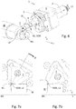
- Figure 6 shows a tool system 1 in a further embodiment.
- this embodiment it is set up that the longitudinal axis L2 of the tool-side shank 3 runs through a cutting corner radius center SEM of the active cutting corner 81 of the cutting tip 7.
- this embodiment has the particular advantage that when the tool-side shaft 3 is rotated, the cutting corner 81 cannot be changed with respect to its infeed relative to the workpiece W. There is therefore no need to compensate for the position of the cutting corner 81 by means of a translational movement of the tool system 1 coordinated with the rotation of the cutting plate 7 in or parallel to the yz plane.
- the longitudinal axis L2 of the tool-side shaft 3 coincides with the longitudinal axis L1 of the machine-side shaft 2.
- the longitudinal axis L2 of the tool-side shaft 3 coincides with the longitudinal axis L1 of the machine-side shaft 2.
- Figures 7a and 7b show an end view of the cutting insert 7 for a configuration according to FIG Figure 6 with two different orientations of the cutting tip 7 with regard to an angle of attack with respect to the workpiece W.
- the cutting corner 81 of the cutting tip 7 is in engagement with the workpiece W.
- the longitudinal axis L2 of the tool-side shaft 3 and thus its axis of rotation runs through the cutting corner radius center SEM of active cutting corner 81.
- the center of a rotary movement of the tool-side shank 3 lies in the cutting corner radius center SEM.
- Figures 8 to 10 show various representations of an exemplary cutting insert 7 which is particularly suitable for use with the tool system 1 according to the invention and for the method according to the invention for machining.
- the cutting tip 7 has the basic shape of an isosceles triangle with an additional corner.
- the cutting tip 7 is designed for one-sided use.
- Figure 8 shows a plan view of the cutting tip 7.
- the top 10 of the cutting tip 7 is designed as a rake face; chip breakers 16a, 16b are formed.
- the cutting insert 7 has three corners that can be used as cutting corners: cutting corners 81, 82, 83. Furthermore, a further corner 84 is formed.
- Cutting edges 91, 92 extend between the cutting corners 81, 82, 83.
- the cutting corners 82, 83 differ from the cutting corner 81, inter alia, in their point angle, that is to say the Angle formed by the cutting edges adjoining the cutting corner.
- the further corner 84 has the effect that the point angle of the cutting corners 81, 82 is enlarged compared to a linear course of a cutting edge 93 between the cutting corners 81, 82.
- different chip breaker steps 16b are formed on the cutting corners 82, 83 as chip breaker steps 16a on the cutting corner 81.
- the cutting corners 82, 83 differ from the cutting corner 81 in their corner radius.
- the cutting insert 7 has a through hole 13 for receiving a clamping screw for fastening in the insert seat.
- Figure 9 shows the cutting tip 7 in a view of the underside 11.
- the underside 11 is designed as a contact surface for a non-rotatable receptacle in an insert seat.
- the top 10 and the bottom 11 are parallel to each other.
- Figure 10 shows the cutting insert 7 of this example in a perspective view.
- various machining operations of a turning machining can be advantageously carried out.
- the cutting insert 7 discussed here is particularly advantageous when machining operations require different forms of cutting corners. For example, it is advantageous to use a cutting corner with a different, preferably smaller tip angle for finishing machining than for coarser machining.
- a special chip breaker step and a different, in particular smaller, corner radius are provided for the cutting corner provided for finishing machining.
- the cutting corner 81 is particularly suitable for finishing machining.
- the cutting corner 81 has a smaller tip angle than the cutting corners 82, 83.
- the cutting corner 81 also has a smaller corner radius than the cutting corners 82, 83, that is to say it is more pointed.
- a chip breaker step 16a assigned to the cutting corner 81 is designed especially for finishing machining: it is more narrowly shaped than, for example, those assigned to the cutting corners 82, 83 Chip breaker 16b. In this way, sufficient chip deformation is achieved even with shallow depths of cut when finishing.
- FIG 11 shows a detail of the tool system 1.
- the tool holder 4 of the tool system 1 is shown with an insert seat 6 formed on the tool holder 4 for receiving an exchangeable cutting insert 7, which insert seat 6 is formed on an end face of the tool holder 4 extending transversely to a longitudinal axis L3 of the tool holder 4 is.
- the cutting insert 7 is fixed in the insert seat by means of a clamping screw 14.
- a clamping force exerted by the clamping screw 14 acts predominantly along the longitudinal axis L3 of the tool holder.
- the top 10 of the cutting tip 7 runs transversely to the longitudinal axis L3 of the tool holder 4.
- the top 10 is perpendicular to the longitudinal axis L3.
- the arrangement shown, according to which the insert seat 6 and the inserted cutting insert 7 are arranged such that the top 10 of the cutting insert 7 runs perpendicular to the longitudinal axis L3 of the tool holder 4, is particularly advantageous.
- the cutting plate 7 and the tool holder 4 are dimensioned and arranged in such a way that at least one cutting corner 8 and cutting edges 9 adjoining it on both sides protrude at least in sections over an outer circumference of the end face of the tool holder 4. More preferably, and as shown in this example, the entire outer circumference of the cutting tip 7 formed by cutting edges 9 protrudes beyond the outer circumference of the tool holder 4. In other words, the cutting insert 7 projects beyond the insert seat 6 along its entire circumference.
- the cutting insert 7 can in principle be used along its entire circumference. In this way, the cutting insert 7 can be left in one and the same assembly situation on the insert seat 6 if, by actuating the tool system 1, other cutting corners 8 and / or cutting edges 9 are to be used for a next machining step.
- Figure 12 shows a tool system 1 in one embodiment in which the longitudinal axis L1 of the machine-side shaft 2 runs essentially perpendicular to the longitudinal axis L2 of the tool-side shaft 3.
- This embodiment of the tool system 1 is particularly advantageous for use with a frontal, that is to say axial, arrangement on a tool carrier, for example on a tool turret with frontal tool holders, a so-called disk turret.
- Figure 13 shows a tool system 1 in an alternative embodiment, in which the longitudinal axis L1 of the machine-side shaft 2 runs parallel and with a lateral offset 15 to the longitudinal axis L2 of the tool-side shaft 3.
- This embodiment of the tool system 1 is particularly advantageous for use with a circumferential, that is, radial arrangement on a tool carrier, for example on a tool turret with radially arranged tool holders, a so-called star turret.
- a cranked configuration can be advantageous in cases in which a travel path of the tool holder in the y-direction is limited.
- the tool system 1 can then initially travel to a stop in the negative y-direction and then double the travel path is available in the positive y-direction. This allows greater leeway with regard to the maximum permissible workpiece diameter.
- a longitudinal axis of the means 21 for transmitting a rotary movement that can be tapped off by the driven tool holder coincides with the longitudinal axis L1 of the machine-side shaft 2.
- Figure 14 shows a tool carrier 12 with several tool holders. According to the explanations above, a distinction is made between radial and axial arrangements on a tool carrier.
- the tool carrier is designed here as a tool turret 12 with radially arranged tool stations. In this case one speaks of a star turret.
- the tool currently required can be swiveled into an operating position by turning the turret disk.
- the tool system 1 according to the invention is arranged on the circumference of the tool turret 12, that is to say radially.
- the tool system 1 is preferably according to the in Figure 13 described embodiment configured.
- the tool turret 12 is designed as a driven tool holder, the drive of which can be used by the tool system 1 to adjust the alignment of the cutting plate 7 attached to it, as described above.
- a tool turret is designed for a frontal, that is to say axial, mounting of tools, it is referred to as a disk turret (not shown here).
- a disk turret (not shown here).
- an embodiment of the tool system 1 is based on the Figure 12 described embodiment particularly advantageous.
- Figures 15a and 15b show an embodiment of the tool system 1 with a cutting insert 7 in a further alternative.
- the cutting tip 7 has the basic shape of an equilateral triangle.
- a basic shape of an equilateral triangle allows, for example, indexing of the cutting tip 7 by a rotation of 120 °, the geometric relationships remaining unchanged due to the three-fold symmetry.
- the tool system 1 according to the invention makes it particularly easy to change from one cutting corner 8 to another, for example unused cutting corner 8, without the cutting insert 7 having to be detached from the insert seat 6.
- Figures 16a to 16d show the cutting insert 7 of Figures 15a and 15b in detail.
- Figure 16a shows a plan view of the top 10, Figure 16b a view from below of the underside 11,
- Figure 16c a perspective view with a view of the top 10,
- Figure 16d a perspective view with a view of the underside 11.
- the top 10 is designed as a rake face
- the bottom 11 is designed as a contact surface for attachment to the insert seat 6.
- the top 10 and the bottom 11 are parallel to each other.
- the cutting plate 7 tapers from the top 10 to the bottom 11, which results in a clearly positive geometry of the cutting edges 9 and cutting corners 8.
- the cutting tip 7 has a three-fold symmetry.
- the cutting insert 7 can be rotated to a next cutting corner 8 by rotating it through 120 °.
- the cutting edges are designed to be concave with respect to a top view of an upper side 10. That is, the cutting edges 9 are drawn in radially towards the center of the cutting tip 7. This enables a particularly small point angle ⁇ to be formed on a cutting corner 8, which is favorable for copy turning. This configuration is very advantageous for copying operations or for finishing and working in narrow grooves.
- corner radii of different sizes can also be provided at different cutting corners 8.
Landscapes
- Engineering & Computer Science (AREA)
- Mechanical Engineering (AREA)
- Cutting Tools, Boring Holders, And Turrets (AREA)
- Turning (AREA)
Priority Applications (4)
| Application Number | Priority Date | Filing Date | Title |
|---|---|---|---|
| EP19216972.0A EP3838455A1 (fr) | 2019-12-17 | 2019-12-17 | Système d'outil |
| US17/786,700 US12397354B2 (en) | 2019-12-17 | 2020-11-10 | Tool system |
| JP2022535873A JP7554266B2 (ja) | 2019-12-17 | 2020-11-10 | ツールシステム |
| PCT/EP2020/081586 WO2021121783A1 (fr) | 2019-12-17 | 2020-11-10 | Système d'outil |
Applications Claiming Priority (1)
| Application Number | Priority Date | Filing Date | Title |
|---|---|---|---|
| EP19216972.0A EP3838455A1 (fr) | 2019-12-17 | 2019-12-17 | Système d'outil |
Publications (1)
| Publication Number | Publication Date |
|---|---|
| EP3838455A1 true EP3838455A1 (fr) | 2021-06-23 |
Family
ID=68944211
Family Applications (1)
| Application Number | Title | Priority Date | Filing Date |
|---|---|---|---|
| EP19216972.0A Pending EP3838455A1 (fr) | 2019-12-17 | 2019-12-17 | Système d'outil |
Country Status (4)
| Country | Link |
|---|---|
| US (1) | US12397354B2 (fr) |
| EP (1) | EP3838455A1 (fr) |
| JP (1) | JP7554266B2 (fr) |
| WO (1) | WO2021121783A1 (fr) |
Cited By (1)
| Publication number | Priority date | Publication date | Assignee | Title |
|---|---|---|---|---|
| EP4286079A1 (fr) * | 2022-06-02 | 2023-12-06 | CERATIZIT Austria Gesellschaft m.b.H. | Système d'outil et procédé pour l'usinage d'une pièce utilisant ce système |
Families Citing this family (1)
| Publication number | Priority date | Publication date | Assignee | Title |
|---|---|---|---|---|
| ES2815542T3 (es) * | 2017-12-22 | 2021-03-30 | Ceratizit Austria Gmbh | Sistema de herramientas y procedimiento de torneado |
Citations (8)
| Publication number | Priority date | Publication date | Assignee | Title |
|---|---|---|---|---|
| US4785513A (en) * | 1986-12-16 | 1988-11-22 | Hardinge Brothers | Turret having rotating and non-rotating tooling |
| DE19940330A1 (de) * | 1999-08-25 | 2001-03-15 | Esa Eppinger Gmbh | Werkzeugspanneinrichtung |
| DE19958461C1 (de) * | 1999-12-03 | 2001-03-15 | Esa Eppinger Gmbh | Werkzeugspanneinrichtung, beispielsweise für Dreh- und Fräsmaschinen |
| WO2004022270A1 (fr) * | 2002-09-03 | 2004-03-18 | Kennametal Inc. | Porte-outil |
| DE10306845A1 (de) * | 2003-02-18 | 2004-09-02 | Universität Bremen | Werkzeug für die spanende Bearbeitung, insbesondere Reibwerkzeug |
| WO2011029944A1 (fr) * | 2009-09-14 | 2011-03-17 | Index-Werke Gmbh & Co. Kg Hahn & Tessky | Unité d'usinage, machine-outil comprenant une telle unité d'usinage et procédé de tournage d'une pièce en rotation |
| EP3246125A1 (fr) * | 2016-05-17 | 2017-11-22 | Vandurit GmbH Hartmetall und Diamantwerkzeuge | Module orientable pour outil pour une machine rotative |
| EP3501701A1 (fr) * | 2017-12-22 | 2019-06-26 | Ceratizit Austria Gesellschaft m.b.H. | Système d'outillage et procédé d'usinage par tournage |
Family Cites Families (16)
| Publication number | Priority date | Publication date | Assignee | Title |
|---|---|---|---|---|
| JPS60167602U (ja) | 1984-04-13 | 1985-11-07 | トヨタ自動車株式会社 | 旋削用切刃中心回転型刃物台 |
| WO1994023874A1 (fr) * | 1993-04-14 | 1994-10-27 | Zettl GmbH CNC Präzisions- und Sonderwerkzeuge | Outil de coupe |
| DE19702219A1 (de) | 1997-01-23 | 1998-07-30 | Komet Stahlhalter Werkzeug | Werkzeugkopf für den Einsatz in Werkzeugmaschinen |
| AT5009U1 (de) * | 2001-05-18 | 2002-02-25 | Plansee Tizit Ag | Verfahren zur drehbearbeitung |
| JP2003039229A (ja) | 2001-07-30 | 2003-02-12 | Nagase Integrex Co Ltd | 研削盤、その研削盤に装着されるワーク切削用アタッチメント及びワークの切削方法 |
| AU2003264104A1 (en) * | 2002-09-09 | 2004-04-30 | Komet Group Holding Gmbh | Drilling tool with alternating cutting plates and alternating cutting plates for said drilling tool |
| SE526480C2 (sv) * | 2002-10-31 | 2005-09-20 | Sandvik Intellectual Property | Verktyg för spånavskiljande bearbetning |
| AT505069B1 (de) | 2007-04-12 | 2009-12-15 | Emco Maier Gmbh | Werkzeugrevolver |
| DE102008036562A1 (de) * | 2008-07-30 | 2010-02-04 | Hartmetall-Werkzeugfabrik Paul Horn Gmbh | Werkzeug für spanende Bearbeitung eines Werkstücks |
| US20110182680A1 (en) * | 2010-01-22 | 2011-07-28 | Ilan Cohen | Cutter and insert |
| DE102010054392A1 (de) * | 2010-12-07 | 2012-06-14 | Hartmetall-Werkzeugfabrik Paul Horn Gmbh | Schneidwerkzeug zur spanenden Bearbeitung eines Werkzeugs |
| IL211113A (en) * | 2011-02-08 | 2015-09-24 | Iscar Ltd | Cutting tools and a tool for him |
| WO2017136429A1 (fr) * | 2016-02-01 | 2017-08-10 | AM Networks LLC | Bras robotique de plan de travail muni d'effecteurs d'extrémité interchangeables |
| EP3536428B2 (fr) * | 2018-03-08 | 2026-03-25 | AB Sandvik Coromant | Procédé de tournage pour tour commandée par ordinateur et outil de tournage |
| EP3536427B1 (fr) * | 2018-03-08 | 2022-08-17 | AB Sandvik Coromant | Procédé de tournage et outil de tournage pour machines cnc |
| EP3863786B1 (fr) * | 2018-10-10 | 2025-06-18 | Sumitomo Electric Hardmetal Corp. | Plaquette de coupe et outil de coupe |
-
2019
- 2019-12-17 EP EP19216972.0A patent/EP3838455A1/fr active Pending
-
2020
- 2020-11-10 JP JP2022535873A patent/JP7554266B2/ja active Active
- 2020-11-10 US US17/786,700 patent/US12397354B2/en active Active
- 2020-11-10 WO PCT/EP2020/081586 patent/WO2021121783A1/fr not_active Ceased
Patent Citations (8)
| Publication number | Priority date | Publication date | Assignee | Title |
|---|---|---|---|---|
| US4785513A (en) * | 1986-12-16 | 1988-11-22 | Hardinge Brothers | Turret having rotating and non-rotating tooling |
| DE19940330A1 (de) * | 1999-08-25 | 2001-03-15 | Esa Eppinger Gmbh | Werkzeugspanneinrichtung |
| DE19958461C1 (de) * | 1999-12-03 | 2001-03-15 | Esa Eppinger Gmbh | Werkzeugspanneinrichtung, beispielsweise für Dreh- und Fräsmaschinen |
| WO2004022270A1 (fr) * | 2002-09-03 | 2004-03-18 | Kennametal Inc. | Porte-outil |
| DE10306845A1 (de) * | 2003-02-18 | 2004-09-02 | Universität Bremen | Werkzeug für die spanende Bearbeitung, insbesondere Reibwerkzeug |
| WO2011029944A1 (fr) * | 2009-09-14 | 2011-03-17 | Index-Werke Gmbh & Co. Kg Hahn & Tessky | Unité d'usinage, machine-outil comprenant une telle unité d'usinage et procédé de tournage d'une pièce en rotation |
| EP3246125A1 (fr) * | 2016-05-17 | 2017-11-22 | Vandurit GmbH Hartmetall und Diamantwerkzeuge | Module orientable pour outil pour une machine rotative |
| EP3501701A1 (fr) * | 2017-12-22 | 2019-06-26 | Ceratizit Austria Gesellschaft m.b.H. | Système d'outillage et procédé d'usinage par tournage |
Cited By (1)
| Publication number | Priority date | Publication date | Assignee | Title |
|---|---|---|---|---|
| EP4286079A1 (fr) * | 2022-06-02 | 2023-12-06 | CERATIZIT Austria Gesellschaft m.b.H. | Système d'outil et procédé pour l'usinage d'une pièce utilisant ce système |
Also Published As
| Publication number | Publication date |
|---|---|
| WO2021121783A1 (fr) | 2021-06-24 |
| JP2023508849A (ja) | 2023-03-06 |
| US12397354B2 (en) | 2025-08-26 |
| JP7554266B2 (ja) | 2024-09-19 |
| US20230015428A1 (en) | 2023-01-19 |
Similar Documents
| Publication | Publication Date | Title |
|---|---|---|
| DE3610016C2 (fr) | ||
| EP1321210B1 (fr) | Outil de chanfreinage | |
| EP3758876B1 (fr) | Outil de chanfreinage, système de chanfreinage, machine à tailler des dentures et procédé servant à chanfreiner des dentures | |
| EP1750879B1 (fr) | Procede et dispositif pour usiner, par enlevement de matiere, des surfaces a symetrie de revolution d'une piece | |
| DE102016102651A1 (de) | Vorrichtung und Verfahren zur spanenden Bearbeitung eines rotierenden Werkstücks | |
| DE102015220777B4 (de) | Werkzeugkupplung zwischen zwei Kupplungsteilen sowie Kupplungsteil für eine solche Werkzeugkupplung | |
| DE68923131T2 (de) | Bohrer, Schleifverfahren und Schleifvorrichtung. | |
| EP4178749A1 (fr) | Dispositif et procédé pour produire des chanfreins sur des flancs de dents d'engrenages et outil de coupe, plaque de coupe et programme de commande associé | |
| DE102020109035B4 (de) | Verfahren und Gewindebohr-Werkzeug zur Erzeugung einer Werkstück-Gewindebohrung | |
| EP3523089A1 (fr) | Dispositif d'alésage-fraisage comportant un dispositif d'égalisation du couple et de la vitesse de la broche | |
| EP1641585A1 (fr) | Plaquette de coupe | |
| EP3784430A1 (fr) | Outil de taraudage et procédé de production d'un trou taraudé | |
| DE4021090C2 (de) | Bearbeitungsvorrichtung mit Mitteln zur Änderung der radialen Position von Schneidwerkzeugen | |
| WO2021121783A1 (fr) | Système d'outil | |
| EP0296460A1 (fr) | Outil pour l'usinage circonferentiel de pièces, en particulier pour le forage | |
| DE102016222595B4 (de) | Verfahren und Fräswerkzeug zur Herstellung einer Kavität in einem Werkstück für die Aufnahme einer Zentrierspitze | |
| DE102017105032A1 (de) | Werkzeug, Maschine und Verfahren zum Erzeugen von dachfirstartigen Anspitzungen an Zähnen eines innen- und außenverzahnten Zahnrads | |
| DE102010010135B3 (de) | Werkzeug und Verfahren zum Herstellen einer Welle | |
| DE4039489A1 (de) | Formbohrer | |
| EP3246125A1 (fr) | Module orientable pour outil pour une machine rotative | |
| EP2477770A1 (fr) | Unité d'usinage, machine-outil comprenant une telle unité d'usinage et procédé de tournage d'une pièce en rotation | |
| DE10127973C2 (de) | Vorrichtung zum Fräsen von Rastnuten und Schaltanschlägen an den Zahnflanken einzelner Zähne von Schiebemuffen für Schaltgetriebe | |
| DE3909643C2 (de) | Mehrschneidenwerkzeugkopf zur spanabhebenden Vor- und Feinbearbeitung mit kreisförmiger Schnittbewegung | |
| DE10333621A1 (de) | Schneideinsatz | |
| EP3908420B1 (fr) | Taraudeuse de production d'un trou fileté |
Legal Events
| Date | Code | Title | Description |
|---|---|---|---|
| PUAI | Public reference made under article 153(3) epc to a published international application that has entered the european phase |
Free format text: ORIGINAL CODE: 0009012 |
|
| STAA | Information on the status of an ep patent application or granted ep patent |
Free format text: STATUS: THE APPLICATION HAS BEEN PUBLISHED |
|
| AK | Designated contracting states |
Kind code of ref document: A1 Designated state(s): AL AT BE BG CH CY CZ DE DK EE ES FI FR GB GR HR HU IE IS IT LI LT LU LV MC MK MT NL NO PL PT RO RS SE SI SK SM TR |
|
| STAA | Information on the status of an ep patent application or granted ep patent |
Free format text: STATUS: REQUEST FOR EXAMINATION WAS MADE |
|
| 17P | Request for examination filed |
Effective date: 20211217 |
|
| RBV | Designated contracting states (corrected) |
Designated state(s): AL AT BE BG CH CY CZ DE DK EE ES FI FR GB GR HR HU IE IS IT LI LT LU LV MC MK MT NL NO PL PT RO RS SE SI SK SM TR |