EP3838541A1 - Moule fabriqué à partir d'une technologie de fabrication additive - Google Patents
Moule fabriqué à partir d'une technologie de fabrication additive Download PDFInfo
- Publication number
- EP3838541A1 EP3838541A1 EP20214832.6A EP20214832A EP3838541A1 EP 3838541 A1 EP3838541 A1 EP 3838541A1 EP 20214832 A EP20214832 A EP 20214832A EP 3838541 A1 EP3838541 A1 EP 3838541A1
- Authority
- EP
- European Patent Office
- Prior art keywords
- edge
- mold
- molding surface
- overlapping interface
- support
- Prior art date
- Legal status (The legal status is an assumption and is not a legal conclusion. Google has not performed a legal analysis and makes no representation as to the accuracy of the status listed.)
- Granted
Links
Images


Classifications
-
- B—PERFORMING OPERATIONS; TRANSPORTING
- B29—WORKING OF PLASTICS; WORKING OF SUBSTANCES IN A PLASTIC STATE IN GENERAL
- B29C—SHAPING OR JOINING OF PLASTICS; SHAPING OF MATERIAL IN A PLASTIC STATE, NOT OTHERWISE PROVIDED FOR; AFTER-TREATMENT OF THE SHAPED PRODUCTS, e.g. REPAIRING
- B29C64/00—Additive manufacturing, i.e. manufacturing of three-dimensional [3D] objects by additive deposition, additive agglomeration or additive layering, e.g. by 3D printing, stereolithography or selective laser sintering
- B29C64/10—Processes of additive manufacturing
- B29C64/106—Processes of additive manufacturing using only liquids or viscous materials, e.g. depositing a continuous bead of viscous material
- B29C64/118—Processes of additive manufacturing using only liquids or viscous materials, e.g. depositing a continuous bead of viscous material using filamentary material being melted, e.g. fused deposition modelling [FDM]
-
- B—PERFORMING OPERATIONS; TRANSPORTING
- B22—CASTING; POWDER METALLURGY
- B22F—WORKING METALLIC POWDER; MANUFACTURE OF ARTICLES FROM METALLIC POWDER; MAKING METALLIC POWDER; APPARATUS OR DEVICES SPECIALLY ADAPTED FOR METALLIC POWDER
- B22F5/00—Manufacture of workpieces or articles from metallic powder characterised by the special shape of the product
- B22F5/007—Manufacture of workpieces or articles from metallic powder characterised by the special shape of the product of moulds
-
- B—PERFORMING OPERATIONS; TRANSPORTING
- B22—CASTING; POWDER METALLURGY
- B22F—WORKING METALLIC POWDER; MANUFACTURE OF ARTICLES FROM METALLIC POWDER; MAKING METALLIC POWDER; APPARATUS OR DEVICES SPECIALLY ADAPTED FOR METALLIC POWDER
- B22F7/00—Manufacture of composite layers, workpieces, or articles, comprising metallic powder, by sintering the powder, with or without compacting wherein at least one part is obtained by sintering or compression
- B22F7/06—Manufacture of composite layers, workpieces, or articles, comprising metallic powder, by sintering the powder, with or without compacting wherein at least one part is obtained by sintering or compression of composite workpieces or articles from parts, e.g. to form tipped tools
- B22F7/062—Manufacture of composite layers, workpieces, or articles, comprising metallic powder, by sintering the powder, with or without compacting wherein at least one part is obtained by sintering or compression of composite workpieces or articles from parts, e.g. to form tipped tools involving the connection or repairing of preformed parts
-
- B—PERFORMING OPERATIONS; TRANSPORTING
- B29—WORKING OF PLASTICS; WORKING OF SUBSTANCES IN A PLASTIC STATE IN GENERAL
- B29C—SHAPING OR JOINING OF PLASTICS; SHAPING OF MATERIAL IN A PLASTIC STATE, NOT OTHERWISE PROVIDED FOR; AFTER-TREATMENT OF THE SHAPED PRODUCTS, e.g. REPAIRING
- B29C33/00—Moulds or cores; Details thereof or accessories therefor
- B29C33/30—Mounting, exchanging or centering
- B29C33/301—Modular mould systems [MMS], i.e. moulds built up by stacking mould elements, e.g. plates, blocks, rods
- B29C33/302—Assembling a large number of mould elements to constitute one cavity
-
- B—PERFORMING OPERATIONS; TRANSPORTING
- B29—WORKING OF PLASTICS; WORKING OF SUBSTANCES IN A PLASTIC STATE IN GENERAL
- B29C—SHAPING OR JOINING OF PLASTICS; SHAPING OF MATERIAL IN A PLASTIC STATE, NOT OTHERWISE PROVIDED FOR; AFTER-TREATMENT OF THE SHAPED PRODUCTS, e.g. REPAIRING
- B29C33/00—Moulds or cores; Details thereof or accessories therefor
- B29C33/38—Moulds or cores; Details thereof or accessories therefor characterised by the material or the manufacturing process
- B29C33/3842—Manufacturing moulds, e.g. shaping the mould surface by machining
-
- B—PERFORMING OPERATIONS; TRANSPORTING
- B29—WORKING OF PLASTICS; WORKING OF SUBSTANCES IN A PLASTIC STATE IN GENERAL
- B29C—SHAPING OR JOINING OF PLASTICS; SHAPING OF MATERIAL IN A PLASTIC STATE, NOT OTHERWISE PROVIDED FOR; AFTER-TREATMENT OF THE SHAPED PRODUCTS, e.g. REPAIRING
- B29C70/00—Shaping composites, i.e. plastics material comprising reinforcements, fillers or preformed parts, e.g. inserts
- B29C70/04—Shaping composites, i.e. plastics material comprising reinforcements, fillers or preformed parts, e.g. inserts comprising reinforcements only, e.g. self-reinforcing plastics
- B29C70/28—Shaping operations therefor
- B29C70/40—Shaping or impregnating by compression not applied
- B29C70/42—Shaping or impregnating by compression not applied for producing articles of definite length, i.e. discrete articles
- B29C70/46—Shaping or impregnating by compression not applied for producing articles of definite length, i.e. discrete articles using matched moulds, e.g. for deforming sheet moulding compounds [SMC] or prepregs
-
- B—PERFORMING OPERATIONS; TRANSPORTING
- B33—ADDITIVE MANUFACTURING TECHNOLOGY
- B33Y—ADDITIVE MANUFACTURING, i.e. MANUFACTURING OF THREE-DIMENSIONAL [3D] OBJECTS BY ADDITIVE DEPOSITION, ADDITIVE AGGLOMERATION OR ADDITIVE LAYERING, e.g. BY 3D PRINTING, STEREOLITHOGRAPHY OR SELECTIVE LASER SINTERING
- B33Y10/00—Processes of additive manufacturing
-
- B—PERFORMING OPERATIONS; TRANSPORTING
- B33—ADDITIVE MANUFACTURING TECHNOLOGY
- B33Y—ADDITIVE MANUFACTURING, i.e. MANUFACTURING OF THREE-DIMENSIONAL [3D] OBJECTS BY ADDITIVE DEPOSITION, ADDITIVE AGGLOMERATION OR ADDITIVE LAYERING, e.g. BY 3D PRINTING, STEREOLITHOGRAPHY OR SELECTIVE LASER SINTERING
- B33Y80/00—Products made by additive manufacturing
Definitions
- the present invention generally relates to the field of molds for the production of molded parts which can be made of composite materials for example. More specifically, the invention relates to a mold made using an additive manufacturing technology and to a method of producing such a mold.
- Molds used in the production of components made from composite materials using a reinforcing fabric in a matrix are typically themselves made out of composite materials.
- Current mold technology first requires the production of a plug, which is an intermediate component representing the surface of the composite material component that is to be ultimately molded in the mold.
- the plug is then polished to a smooth finish.
- the mold, itself made from layered composite materials, is then molded over the plug. Only then can the mold be used to produce components made from layered composite materials. The mold manufacturing process is rather long, tedious, and expensive.
- additive manufacturing technologies also known as 3D printing techniques, which may directly produce finished components, thereby saving time and money.
- additive manufacturing technologies have been used to produce molds for the production of components made of layered composite materials. These printed molds are however limited to the size of the additive manufacturing machine used to print them. This is a problem when the production of large composite components requires a mold exceeding the capacity of the additive manufacturing machine.
- StratasysTM For molds larger than the build chamber of the additive manufacturing machine, StratasysTM, a manufacturer of additive manufacturing machines, published in its Design Guide that molds may be segmented. The different segments of the mold may then by joined with secondary operations, such as thermal welding or structural bonding. To assist in assembly, StratasysTM suggests using joint features incorporated into the mold design to ensure proper fit and alignment. Common assembly joining techniques such as tongue and groove, dovetails, and saw-tooth patterns are recommended.
- the invention provides the advantages of precisely locating the surfaces of adjacent mold segments so as to create a continuous molding surface from one segment to another. Moreover, the bonding area between segments is improved and the sealing of the molding surface is also improved.
- an open mold for producing components made of a moldable material such as layered composite materials comprising a first mold segment and a second mold segment both made from an additive manufacturing technology.
- the first mold segment comprises:
- the first overlapping interface overlaps the second overlapping interface.
- the second overlapping interface abuts against the first overlapping interface in a direction normal to the interlocking plane so that the first edge is juxtaposed with the second edge and so that the first molding surface is juxtaposed with the second molding surface.
- the term "juxtaposed” here is understood to mean “placed side by side” and not “contrasted” or "compared”.
- the first interlocking element may be a male interlocking element.
- the second interlocking element is a female interlocking element and vice-versa.
- the first interlocking element is located remotely from the first edge and at a second predetermined distance from the first edge while the second interlocking element is also located remotely from the second edge and at the same second predetermined distance from the second edge.
- the predetermined distance is measured in the interlocking plane which, preferably, is parallel to the support plane.
- the first mold segment may further comprise a sealing zone in the first overlapping interface.
- the sealing zone is located between the first edge and the first interlocking element.
- the second mold segment then comprises a depression in the second overlapping interface. The depression contains an adhesive contacting the sealing zone.
- the second mold segment may be the one comprising the sealing zone which is then located in the second overlapping interface.
- the sealing zone is located between the second edge and the second interlocking element.
- the first mold segment then comprises a depression in the first overlapping interface. The depression contains the adhesive which contacts the sealing zone.
- the first edge and the second edge may be parallel.
- the first molding surface and the second molding surface may be tangent to each other in a plane that is normal to the first edge.
- the second mold segment is welded to the first mold segment along the first edge and a finishing layer is applied on the first molding surface and on the second molding surface.
- first support and the second support partially overlap each other in a second overlapping interface.
- An adhesive may also be applied in this second overlapping interface.
- a method for manufacturing an open mold adapted to produce components made of a moldable material such as layered composite materials comprises:
- the molding surface may be tangent to the first molding surface in a plane normal to the first edge.
- the interlocking may further comprise interlocking in a plane parallel to a common support plane defined by the first support and the second support, the common support plane being coplanar with the first support plane and second support plane.
- the method may further comprise applying an adhesive in a depression of one of the first and the second overlapping interfaces and then pressing the first and the second mold segments against each other so as to wet a sealing zone of the other one of the first and the second overlapping interfaces with the adhesive.
- the method may also comprise welding the second mold segment to the first mold segment along the first edge.
- the method may further comprise polishing the first molding surface and the second molding surface. It may also include applying a finishing layer on the first molding surface and on the second molding surface.
- the method may further comprise overlapping the first support with the second support, thereby defining a second overlapping interface. It may also include applying an adhesive on the second overlapping interface.
- the present invention relates to an open mold for layered composite materials and a method for manufacturing such a mold where the mold is made of segments which interlock and abut precisely with each other to generate a continuous molding surface.
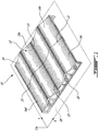
- Figure 1 shows a mold 10 and its molding surface 12.
- the mold 10 as shown only stretches to the limits of a part to be molded and does not include trimming extensions to the molding surface 12 which are typically added to provide a neat cutting surface.
- the mold 10 is of the open type and is adapted to receive a moldable material, such as reinforced layered composite materials, in order to produce components made of this moldable material.
- the mold 10 is made from an additive manufacturing technology, such as VAT Photopolymerization, Material Jetting, Binder Jetting, Material Extrusion (commonly known as Fuse Deposition Modelling (FDM) or 3D Printing), Powder Bed Fusion, Sheet Lamination or Directed Energy Deposition or any other adequate additive manufacturing technology. Guidelines for to the selection of the right process as well as for the selection of a suitable mold material are already documented in reference documents such as Stratasys® Design Guide for composite tooling. These will therefore not be further described here.
- VAT Photopolymerization Material Jetting, Binder Jetting, Material Extrusion (commonly
- the mold 10 is split in at least two segments 14.
- the mold 10 is split in four segments 14a, 14b, 14c and 14d, although in a more general case, the mold 10 may be made of any number of segments 14 greater or equal to two. These segments 14 may be manufactured sequentially on the same machine and then assembled together.
- the mold 10 also comprises a support 16 made to rest on a horizontal surface, and which thereby defines a supporting plane 18.
- the supporting plane 18 is here defined as being in the X-Y plane. A Z axis is therefore normal to the supporting plane 18.
- the molding surface 12 rests on the support 16.
- the support 16 is best shown in Figure 2 , now concurrently referred to.
- the supporting plane 18 corresponds to the underside of the support 16 and is coplanar for all segments 14.
- the support 16 of a given segment 14 is made to overlap that of an adjacent segment 14 at a support overlapping interface 20.
- the segments 14 may be detachably or permanently attached to one another by attaching together adjacent supports 16 at their common support overlapping interface 20 using an adhesive, plastic welding, fasteners, or any other adequate joining technique.
- Each mold segment 14 comprises its own portion of molding surface 12 bordered by at least one edge 22, at least one overlapping interface 24 and at least one interlocking element 26.
- each mold segment 14 comprises at least one edge 22, at least one overlapping interface 24 and at least one interlocking element 26 for each other adjacent mold segment 14 to which it is connected.
- edge 22 and overlapping interface 24 may each be continuous so that only a portion of them interfaces with an adjacent segment 14.
- edge 22 and the overlapping interface 24 do not have necessarily to be rectilinear. For example, they could be curved.
- edges 22a, 22b of the two adjacent mold segments 14a, 14b are designed to match closely together once assembled since a minimum gap between each adjacent molding surface 12a, 12b is desired.
- edges 22a and 22b, respectively of mold segments 14a and 14b are designed to end up parallel and as close as possible once the segments 14a, 14b are assembled together, while still providing sufficient fit tolerance to easily assemble the adjacent segments 14a, 14b.
- Molding surfaces 12a, 12b may be designed to end up being tangent to each other in a plane that is normal to the edge 22 (either 22a or 22b) once assembled. Although such tangency between adjacent surfaces 12 is usual, it may not be absolutely required if, for example, there is a discontinuity in the molding surface 12. It is however the case when the component to be molded has a continuous surface but requires a mold that is too large for the capacity of the additive manufacturing machine.
- the overlapping interface 24 is located at a predetermined distance D from the edge 22, anywhere between the support plane 18, best shown in Figure 4 , now concurrently referred to, and edge 22.
- the predetermined distance D is measured in the Z direction, that is normal to the supporting plane 18.
- a point Pa on the overlapping interface 24a is located at the same predetermined distance D as a corresponding point Pb located on the overlapping interface 24b.
- the overlapping interface 24 be located in close proximity to the molding surface 12 so as to minimize dimensional variance caused by manufacturing tolerances.
- the overlapping interface 24 may be parallel to the supporting plane 18 while always remaining below the molding surface 12, or it may follow the molding surface 12 by being offset underneath the molding surface 12 by the predetermined distance D.
- the predetermined distance D of corresponding points on each overlapping interface 24 must be the same for both mold segments 14. This is the case in the example illustrated with points Pa and Pb of mold segments 14a and 14b.
- overlapping interface 24a of mold segment 14a is designed to extend beyond its edge 22a by a predetermined distance W while the overlapping interface 24b of adjacent mold segment 14b is made to extend behind, or is set back from, its edge 22b, by at least an equivalent predetermined distance W.
- the overlapping interface 24 is designed to be sufficiently wide (width being understood as extending in the direction of the adjacent mold segment) so as to provide a large overlapping area to attach together adjacent mold segments 14a, 14b, preferably using an adhesive.
- depressions 28 in which the adhesive is contained may be located in either one or both of the overlapping interfaces 24a and 24b. These depressions 28 may take different shapes. In fact, depressions 28 may be so broad so as to occupy most of the surface of the overlapping interface 24, only leaving small abutting areas, or posts, scattered on the overlapping interface 24, and with which the predetermined distance D is controlled. Alternatively, a single depression 28 could be used, defined by a ridge all around the overlapping interface 24.
- supports 16a and 16b are provided with their own support overlapping interface 20a, 20b.
- An adhesive may also be applied to the support overlapping interfaces 20a, 20b to further rigidify mold 10.
- At least one set of compatible interlocking elements 26 is provided.
- the compatible interlocking elements 26 are located in or proximate the overlapping interfaces 24 of each mold segment 14a, 14b intended to overlap one another.
- the interlocking elements 26 are positioned at a predetermined distance L from the respective edge 22 of their mold segment 14. In other words, the point Pa on interlocking element 26a is located at the same predetermined distance L as the corresponding point Pb on the interlocking element 26b of mold segment 14b.
- the interlocking plane is parallel to the supporting plane 18. This means that the locking of compatible interlocking elements 26 occurs in interlocking direction 30 which is normal to the supporting plane 18 and along the Z axis. This also means that the predetermined distance D is measured in the same interlocking direction 30, or normal to the interlocking plane.
- the edges 22 on the mold surfaces 12 may adopt a shape that is different from the shape of both the overlapping interface 24 and of the interlocking element 26.
- the interlocking elements 26 are offset both laterally from edge 22 and vertically underneath the molding surface 12, thereby creating a sealing zone 29.
- This sealing zone 29 provides a space between the top molding surface 12 and an underside 32 of the mold segment 14 which can be filled with adhesive.
- the sealing zone 29 is located between the edge 22 and the interlocking elements 26. This space contributes to sealing the top molding surface 12 from air infiltrations through joints and interstices on the underside 32, especially around the interlocking elements 26 which may have discontinuous shapes that are difficult to seal.
- the sealing zone 29 of one mold segment 14, for example mold segment 14b is preferably flat so as to be easily sealed by the adhesive contained in the one or more depressions 28 located in an area of the overlapping interface 24a of the interlocked mold segment 14a which ends up being directly in contact with the sealing zone 29.
- a first interlocking element in mold segment 14a may be of a female type while a second interlocking element in mold segment 14b may be of a male type, or vice-versa.
- the set of compatible interlocking elements 26a, 26b of the two adjacent mold segments 14a, 14b may define a dovetail assembly. Note that the compatibility of each male-female interlocking elements 26 between each adjacent mold segment 14 is independent.
- a first mold segment 14a could have a male set of interlocking elements 26 for interlocking with a second mold segment 14b and a female set of interlocking elements 26 for interlocking with a third mold segment 14c.
- the mold segments 14a, 14b are assembled by aligning the corresponding compatible interlocking elements 26a, 26b and bringing together both mold segments 14a, 14b along the Z axis until the overlapping interfaces 24a, 24b abut against each other.
- the compatible interlocking elements 26a, 26b precisely locate edges 22a and 22b beside each other, and most importantly precisely juxtapose molding surfaces 12a, 12b with respect to each other so as to create, when required, a continuous molding surface 12.
- combining the compatible interlocking elements 26a, 26b with the overlapping interfaces 24a, 24b allows holding captive in 5 directions both mold segments 14a, 14b with respect to each other.
- the compatible interlocking elements 26a, 26b hold captive the mold segments 14a, 14b in the X-Y plane while the overlapping interfaces 24a, 24b prevent both mold segments 14a, 14b from moving in one of Z+ or Z- direction, depending which mold segment is used as a reference.
- the adhesive applied to the overlapping interfaces 24a, 24b prevents the mold segments 14a, 14b from moving with respect to each other in the opposite Z- or Z+ direction, thereby completely securing both mold segments 14a, 14b together.
- the mold segments 14a, 14b may be welded together along their parallel edges 22a, 22b. Although not absolutely necessary when the mold segments 14a, 14b are already bonded together at their overlapping interface 24, welding along edges 22 allow filling an eventual small assembly gap. Filler material made of either plastic or metal (depending as to whether the mold 10 has been manufactured respectively out of plastic or metal) may therefore be used during welding to better fill this assembly gap.
- the molding surface 12 may be abraded to smooth out perceptible build lines, and then sealed. The molding surface 12 may then undergo a final polish, resulting in surface finishes consistent with typical industry requirements. Sealing can be performed using a range of materials depending on specific application. The most common materials used are high-temperature, two-part epoxy adhesives. Epoxy film adhesives, adhesive-backed FEP films and similar products have also been used.
- common mold-release agents may be applied in preparation for laying up the molded part.
- the mold segment 14 may be manufactured by gradually building the molding surface 12 in a cross-flow direction 35, that is a direction normal to a printing bed 34 of the additive manufacturing machine.
- a first portion 36 of the support 16 is printed in a flow direction, that is in a plan parallel to the printing bed 34 while a second portion 38 of the support 16 is printed in the cross-flow direction.
- the second portion 38 of the support 16 may have openings 40.
- the openings 40 may have sides printed at substantially 45 degrees from the cross-flow direction.
- sides of the interlocking elements 26 may be printed at angles ranging from 1 to 45 degrees from the printing bed 34 to provide interlocking faces 42 of the interlocking element 26, while using the capacity of the additive manufacturing machine to print at such angles without recourse to a detachable printed supporting structure.
- the method of manufacturing the mold 10 comprises manufacturing at least a first and a second mold segments 14 using an additive manufacturing technology.
- Manufacturing the first mold segment 14 comprises:
- the method comprises manufacturing a second mold segment 14b also using the additive manufacturing technology.
- the manufacturing the second mold segment 14b comprises:
- first and the second mold segments 14a, 14b can be assembled by interlocking the second interlocking element 26b with the first interlocking element 26a at 300. This compatibly interlocks the first mold segment 14a with the second mold segment 14b in the interlocking plane parallel to the supporting plane 18. Finally, a step of abutting or pressing the second overlapping interface 24b against the first overlapping interface 24a in a direction normal to the interlocking plane so as to juxtapose the second edge 22b with the first edge 22a, the second molding surface 12b with the first molding surface 12a and the first overlapping interface 24a with the second overlapping interface 24b.
- the adhesive may be applied in one of the overlapping interfaces 24a, 24b, preferably in the depressions 28, prior to the step of abutting, so as to permanently bond both mold segments 14a, 14b together.
- Surfaces 12a, 12b may be welded together.
Landscapes
- Engineering & Computer Science (AREA)
- Manufacturing & Machinery (AREA)
- Mechanical Engineering (AREA)
- Chemical & Material Sciences (AREA)
- Materials Engineering (AREA)
- Composite Materials (AREA)
- Physics & Mathematics (AREA)
- Optics & Photonics (AREA)
- Moulds For Moulding Plastics Or The Like (AREA)
Applications Claiming Priority (1)
| Application Number | Priority Date | Filing Date | Title |
|---|---|---|---|
| CA3065462A CA3065462C (fr) | 2019-12-18 | 2019-12-18 | Moule fabrique au moyen d`une technologie de fabrication additive |
Publications (2)
| Publication Number | Publication Date |
|---|---|
| EP3838541A1 true EP3838541A1 (fr) | 2021-06-23 |
| EP3838541B1 EP3838541B1 (fr) | 2023-08-09 |
Family
ID=69891493
Family Applications (1)
| Application Number | Title | Priority Date | Filing Date |
|---|---|---|---|
| EP20214832.6A Active EP3838541B1 (fr) | 2019-12-18 | 2020-12-17 | Moule fabriqué à partir d'une technologie de fabrication additive |
Country Status (4)
| Country | Link |
|---|---|
| US (1) | US11040467B1 (fr) |
| EP (1) | EP3838541B1 (fr) |
| CN (1) | CN113001964B (fr) |
| CA (1) | CA3065462C (fr) |
Families Citing this family (6)
| Publication number | Priority date | Publication date | Assignee | Title |
|---|---|---|---|---|
| US11179797B2 (en) | 2020-04-10 | 2021-11-23 | The Boeing Company | Article comprising additively manufactured metal portions |
| CN111958888A (zh) * | 2020-08-10 | 2020-11-20 | 泉州市超捷三维科技有限公司 | 一种利用3d打印技术打印轮胎模具的方法 |
| US12583033B2 (en) * | 2021-08-13 | 2026-03-24 | Divergent Technologies, Inc. | Integrating additively-manufactured components |
| US11801619B2 (en) * | 2021-10-05 | 2023-10-31 | The Boeing Company | Rapid tooling layup mandrel |
| CN113910506B (zh) * | 2021-10-07 | 2024-05-14 | 浙江抟原复合材料有限公司 | 一种3d打印技术制备大型复合材料模具的方法 |
| CN114248377A (zh) * | 2021-11-09 | 2022-03-29 | 浙江抟原复合材料有限公司 | 一种复合材料rtm模具制备方法 |
Citations (4)
| Publication number | Priority date | Publication date | Assignee | Title |
|---|---|---|---|---|
| US20060257511A1 (en) * | 2002-11-01 | 2006-11-16 | Kabushiki Kaisha Bridgestone | Method for producing tire vulcanizing mold and tire vulcanizing mold |
| US20110304082A1 (en) * | 2008-12-17 | 2011-12-15 | Michelin Recherche Et Technique S.A. | Mould lining comprising a sacrificial connecting element |
| US20180222081A1 (en) * | 2017-02-03 | 2018-08-09 | Gouda-Torgerson Building Systems Llc | Modular mold sets and methods for manufacturing construction blocks |
| EP3590692A2 (fr) * | 2018-06-14 | 2020-01-08 | The Boeing Company | Ensemble d'outils pour fabrication de pièces composites |
Family Cites Families (7)
| Publication number | Priority date | Publication date | Assignee | Title |
|---|---|---|---|---|
| FR2856333B1 (fr) * | 2003-06-19 | 2005-08-26 | Sidel Sa | Dispositif de moulage pour la fabrication de recipients en materiau thermoplastique |
| DE202011003443U1 (de) * | 2011-03-02 | 2011-12-23 | Bego Medical Gmbh | Vorrichtung zur generativen Herstellung dreidimensionaler Bauteile |
| WO2015054446A1 (fr) * | 2013-10-10 | 2015-04-16 | Option 3 Solutions, Inc. | Système et procédé de moulage de morceaux consécutifs |
| US9943991B2 (en) * | 2014-05-21 | 2018-04-17 | Align Technology, Inc. | Mold with separable features |
| US10983504B2 (en) * | 2015-09-30 | 2021-04-20 | Renishaw Plc | Control of a chain of machines, including an additive manufacturing machine, in the manufacture of a workpiece |
| DE102017214340A1 (de) * | 2017-08-17 | 2019-02-21 | Airbus Operations Gmbh | Verfahren zur Herstellung eines Sandwichbauteils, Kern für ein Sandwichbauteil sowie Sandwichbauteil |
| CN110328811B (zh) * | 2019-08-26 | 2021-06-04 | 余江县富昌模具配件有限公司 | 一种半溢式注射模的伞架司筒顶针脱模的新型注塑模具 |
-
2019
- 2019-12-18 CA CA3065462A patent/CA3065462C/fr active Active
-
2020
- 2020-11-12 CN CN202011261150.XA patent/CN113001964B/zh not_active Expired - Fee Related
- 2020-12-17 US US17/124,566 patent/US11040467B1/en not_active Expired - Fee Related
- 2020-12-17 EP EP20214832.6A patent/EP3838541B1/fr active Active
Patent Citations (4)
| Publication number | Priority date | Publication date | Assignee | Title |
|---|---|---|---|---|
| US20060257511A1 (en) * | 2002-11-01 | 2006-11-16 | Kabushiki Kaisha Bridgestone | Method for producing tire vulcanizing mold and tire vulcanizing mold |
| US20110304082A1 (en) * | 2008-12-17 | 2011-12-15 | Michelin Recherche Et Technique S.A. | Mould lining comprising a sacrificial connecting element |
| US20180222081A1 (en) * | 2017-02-03 | 2018-08-09 | Gouda-Torgerson Building Systems Llc | Modular mold sets and methods for manufacturing construction blocks |
| EP3590692A2 (fr) * | 2018-06-14 | 2020-01-08 | The Boeing Company | Ensemble d'outils pour fabrication de pièces composites |
Also Published As
| Publication number | Publication date |
|---|---|
| EP3838541B1 (fr) | 2023-08-09 |
| US20210187792A1 (en) | 2021-06-24 |
| CA3065462C (fr) | 2021-01-19 |
| CA3065462A1 (fr) | 2020-03-18 |
| US11040467B1 (en) | 2021-06-22 |
| CN113001964A (zh) | 2021-06-22 |
| CN113001964B (zh) | 2023-08-04 |
Similar Documents
| Publication | Publication Date | Title |
|---|---|---|
| EP3838541B1 (fr) | Moule fabriqué à partir d'une technologie de fabrication additive | |
| EP4019220B1 (fr) | Procédé de fabrication de structure préformée assemblée et procédé de fabrication de structure de panneau mural | |
| US20120055619A1 (en) | Systems and Methods for Fabricating Composite Fiberglass Laminate Articles | |
| CN105856592A (zh) | 一种多梁多筋复合材料壁板的成型方法 | |
| CN109228394B (zh) | 一种复合材料机身加强筋的快速成型方法 | |
| JP7193377B2 (ja) | 接合部材 | |
| CN113002012B (zh) | 一种正六边形复合材料开口壳体的铺层方法 | |
| CN117401148A (zh) | 一种用于飞机的牺牲层及铺贴方法 | |
| JP6133463B1 (ja) | ラッピング化粧板及びその製造方法 | |
| JP2017052286A (ja) | ラッピング化粧板の製造方法 | |
| CN105690794B (zh) | 汽车外覆盖件和汽车以及汽车外覆盖件的制作方法 | |
| CN109228395B (zh) | 一种复合材料机身加强筋的成型方法 | |
| JP4213443B2 (ja) | 複合材補強パネルの製造方法 | |
| JPH02233234A (ja) | スラッシュ成形部材の接合方法 | |
| JPH071421Y2 (ja) | 直貼り用床部材 | |
| JP6200538B1 (ja) | ラッピング化粧板及びその製造方法 | |
| RU2358876C2 (ru) | Способ получения слоистого материала с взаимно смещенными слоями | |
| JP2982002B2 (ja) | ハニカムパネルの製造方法 | |
| CN120506416A (zh) | 一种复合材料车顶粘接定位工装及方法 | |
| JPH01280535A (ja) | 自動車用ドアトリムの製造方法 | |
| ITUB20156097A1 (it) | Metodo per la realizzazione di un pannello multistrato in materiale composito | |
| JPS5955726A (ja) | フエアリングの製造方法 | |
| JPH0617949Y2 (ja) | 床 材 | |
| JPS6332615B2 (fr) | ||
| WO2018216097A1 (fr) | Panneau décoratif recouvert et son procédé de production |
Legal Events
| Date | Code | Title | Description |
|---|---|---|---|
| PUAI | Public reference made under article 153(3) epc to a published international application that has entered the european phase |
Free format text: ORIGINAL CODE: 0009012 |
|
| STAA | Information on the status of an ep patent application or granted ep patent |
Free format text: STATUS: THE APPLICATION HAS BEEN PUBLISHED |
|
| AK | Designated contracting states |
Kind code of ref document: A1 Designated state(s): AL AT BE BG CH CY CZ DE DK EE ES FI FR GB GR HR HU IE IS IT LI LT LU LV MC MK MT NL NO PL PT RO RS SE SI SK SM TR |
|
| STAA | Information on the status of an ep patent application or granted ep patent |
Free format text: STATUS: REQUEST FOR EXAMINATION WAS MADE |
|
| 17P | Request for examination filed |
Effective date: 20211222 |
|
| RBV | Designated contracting states (corrected) |
Designated state(s): AL AT BE BG CH CY CZ DE DK EE ES FI FR GB GR HR HU IE IS IT LI LT LU LV MC MK MT NL NO PL PT RO RS SE SI SK SM TR |
|
| STAA | Information on the status of an ep patent application or granted ep patent |
Free format text: STATUS: EXAMINATION IS IN PROGRESS |
|
| 17Q | First examination report despatched |
Effective date: 20220405 |
|
| GRAP | Despatch of communication of intention to grant a patent |
Free format text: ORIGINAL CODE: EPIDOSNIGR1 |
|
| STAA | Information on the status of an ep patent application or granted ep patent |
Free format text: STATUS: GRANT OF PATENT IS INTENDED |
|
| INTG | Intention to grant announced |
Effective date: 20230222 |
|
| GRAS | Grant fee paid |
Free format text: ORIGINAL CODE: EPIDOSNIGR3 |
|
| GRAA | (expected) grant |
Free format text: ORIGINAL CODE: 0009210 |
|
| STAA | Information on the status of an ep patent application or granted ep patent |
Free format text: STATUS: THE PATENT HAS BEEN GRANTED |
|
| AK | Designated contracting states |
Kind code of ref document: B1 Designated state(s): AL AT BE BG CH CY CZ DE DK EE ES FI FR GB GR HR HU IE IS IT LI LT LU LV MC MK MT NL NO PL PT RO RS SE SI SK SM TR |
|
| REG | Reference to a national code |
Ref country code: GB Ref legal event code: FG4D |
|
| REG | Reference to a national code |
Ref country code: CH Ref legal event code: EP |
|
| REG | Reference to a national code |
Ref country code: DE Ref legal event code: R081 Ref document number: 602020015354 Country of ref document: DE Owner name: ALSTOM HOLDINGS, FR Free format text: FORMER OWNERS: BELL TEXTRON INC., MIRABEL, QC, CA; BOMBARDIER TRANSPORTATION GMBH, 10785 BERLIN, DE |
|
| REG | Reference to a national code |
Ref country code: IE Ref legal event code: FG4D |
|
| REG | Reference to a national code |
Ref country code: DE Ref legal event code: R096 Ref document number: 602020015354 Country of ref document: DE |
|
| RAP2 | Party data changed (patent owner data changed or rights of a patent transferred) |
Owner name: BELL TEXTRON INC. Owner name: ALSTOM HOLDINGS |
|
| P01 | Opt-out of the competence of the unified patent court (upc) registered |
Effective date: 20230822 |
|
| REG | Reference to a national code |
Ref country code: LT Ref legal event code: MG9D |
|
| REG | Reference to a national code |
Ref country code: NL Ref legal event code: MP Effective date: 20230809 |
|
| REG | Reference to a national code |
Ref country code: AT Ref legal event code: MK05 Ref document number: 1596990 Country of ref document: AT Kind code of ref document: T Effective date: 20230809 |
|
| PG25 | Lapsed in a contracting state [announced via postgrant information from national office to epo] |
Ref country code: GR Free format text: LAPSE BECAUSE OF FAILURE TO SUBMIT A TRANSLATION OF THE DESCRIPTION OR TO PAY THE FEE WITHIN THE PRESCRIBED TIME-LIMIT Effective date: 20231110 |
|
| PG25 | Lapsed in a contracting state [announced via postgrant information from national office to epo] |
Ref country code: IS Free format text: LAPSE BECAUSE OF FAILURE TO SUBMIT A TRANSLATION OF THE DESCRIPTION OR TO PAY THE FEE WITHIN THE PRESCRIBED TIME-LIMIT Effective date: 20231209 |
|
| PG25 | Lapsed in a contracting state [announced via postgrant information from national office to epo] |
Ref country code: SE Free format text: LAPSE BECAUSE OF FAILURE TO SUBMIT A TRANSLATION OF THE DESCRIPTION OR TO PAY THE FEE WITHIN THE PRESCRIBED TIME-LIMIT Effective date: 20230809 Ref country code: RS Free format text: LAPSE BECAUSE OF FAILURE TO SUBMIT A TRANSLATION OF THE DESCRIPTION OR TO PAY THE FEE WITHIN THE PRESCRIBED TIME-LIMIT Effective date: 20230809 Ref country code: PT Free format text: LAPSE BECAUSE OF FAILURE TO SUBMIT A TRANSLATION OF THE DESCRIPTION OR TO PAY THE FEE WITHIN THE PRESCRIBED TIME-LIMIT Effective date: 20231211 Ref country code: NO Free format text: LAPSE BECAUSE OF FAILURE TO SUBMIT A TRANSLATION OF THE DESCRIPTION OR TO PAY THE FEE WITHIN THE PRESCRIBED TIME-LIMIT Effective date: 20231109 Ref country code: NL Free format text: LAPSE BECAUSE OF FAILURE TO SUBMIT A TRANSLATION OF THE DESCRIPTION OR TO PAY THE FEE WITHIN THE PRESCRIBED TIME-LIMIT Effective date: 20230809 Ref country code: LV Free format text: LAPSE BECAUSE OF FAILURE TO SUBMIT A TRANSLATION OF THE DESCRIPTION OR TO PAY THE FEE WITHIN THE PRESCRIBED TIME-LIMIT Effective date: 20230809 Ref country code: LT Free format text: LAPSE BECAUSE OF FAILURE TO SUBMIT A TRANSLATION OF THE DESCRIPTION OR TO PAY THE FEE WITHIN THE PRESCRIBED TIME-LIMIT Effective date: 20230809 Ref country code: IS Free format text: LAPSE BECAUSE OF FAILURE TO SUBMIT A TRANSLATION OF THE DESCRIPTION OR TO PAY THE FEE WITHIN THE PRESCRIBED TIME-LIMIT Effective date: 20231209 Ref country code: HR Free format text: LAPSE BECAUSE OF FAILURE TO SUBMIT A TRANSLATION OF THE DESCRIPTION OR TO PAY THE FEE WITHIN THE PRESCRIBED TIME-LIMIT Effective date: 20230809 Ref country code: GR Free format text: LAPSE BECAUSE OF FAILURE TO SUBMIT A TRANSLATION OF THE DESCRIPTION OR TO PAY THE FEE WITHIN THE PRESCRIBED TIME-LIMIT Effective date: 20231110 Ref country code: FI Free format text: LAPSE BECAUSE OF FAILURE TO SUBMIT A TRANSLATION OF THE DESCRIPTION OR TO PAY THE FEE WITHIN THE PRESCRIBED TIME-LIMIT Effective date: 20230809 Ref country code: AT Free format text: LAPSE BECAUSE OF FAILURE TO SUBMIT A TRANSLATION OF THE DESCRIPTION OR TO PAY THE FEE WITHIN THE PRESCRIBED TIME-LIMIT Effective date: 20230809 |
|
| PG25 | Lapsed in a contracting state [announced via postgrant information from national office to epo] |
Ref country code: PL Free format text: LAPSE BECAUSE OF FAILURE TO SUBMIT A TRANSLATION OF THE DESCRIPTION OR TO PAY THE FEE WITHIN THE PRESCRIBED TIME-LIMIT Effective date: 20230809 |
|
| PG25 | Lapsed in a contracting state [announced via postgrant information from national office to epo] |
Ref country code: ES Free format text: LAPSE BECAUSE OF FAILURE TO SUBMIT A TRANSLATION OF THE DESCRIPTION OR TO PAY THE FEE WITHIN THE PRESCRIBED TIME-LIMIT Effective date: 20230809 |
|
| PG25 | Lapsed in a contracting state [announced via postgrant information from national office to epo] |
Ref country code: SM Free format text: LAPSE BECAUSE OF FAILURE TO SUBMIT A TRANSLATION OF THE DESCRIPTION OR TO PAY THE FEE WITHIN THE PRESCRIBED TIME-LIMIT Effective date: 20230809 Ref country code: RO Free format text: LAPSE BECAUSE OF FAILURE TO SUBMIT A TRANSLATION OF THE DESCRIPTION OR TO PAY THE FEE WITHIN THE PRESCRIBED TIME-LIMIT Effective date: 20230809 Ref country code: ES Free format text: LAPSE BECAUSE OF FAILURE TO SUBMIT A TRANSLATION OF THE DESCRIPTION OR TO PAY THE FEE WITHIN THE PRESCRIBED TIME-LIMIT Effective date: 20230809 Ref country code: EE Free format text: LAPSE BECAUSE OF FAILURE TO SUBMIT A TRANSLATION OF THE DESCRIPTION OR TO PAY THE FEE WITHIN THE PRESCRIBED TIME-LIMIT Effective date: 20230809 Ref country code: DK Free format text: LAPSE BECAUSE OF FAILURE TO SUBMIT A TRANSLATION OF THE DESCRIPTION OR TO PAY THE FEE WITHIN THE PRESCRIBED TIME-LIMIT Effective date: 20230809 Ref country code: CZ Free format text: LAPSE BECAUSE OF FAILURE TO SUBMIT A TRANSLATION OF THE DESCRIPTION OR TO PAY THE FEE WITHIN THE PRESCRIBED TIME-LIMIT Effective date: 20230809 Ref country code: SK Free format text: LAPSE BECAUSE OF FAILURE TO SUBMIT A TRANSLATION OF THE DESCRIPTION OR TO PAY THE FEE WITHIN THE PRESCRIBED TIME-LIMIT Effective date: 20230809 |
|
| REG | Reference to a national code |
Ref country code: DE Ref legal event code: R097 Ref document number: 602020015354 Country of ref document: DE |
|
| PG25 | Lapsed in a contracting state [announced via postgrant information from national office to epo] |
Ref country code: IT Free format text: LAPSE BECAUSE OF FAILURE TO SUBMIT A TRANSLATION OF THE DESCRIPTION OR TO PAY THE FEE WITHIN THE PRESCRIBED TIME-LIMIT Effective date: 20230809 |
|
| PLBE | No opposition filed within time limit |
Free format text: ORIGINAL CODE: 0009261 |
|
| STAA | Information on the status of an ep patent application or granted ep patent |
Free format text: STATUS: NO OPPOSITION FILED WITHIN TIME LIMIT |
|
| REG | Reference to a national code |
Ref country code: DE Ref legal event code: R119 Ref document number: 602020015354 Country of ref document: DE |
|
| 26N | No opposition filed |
Effective date: 20240513 |
|
| PG25 | Lapsed in a contracting state [announced via postgrant information from national office to epo] |
Ref country code: SI Free format text: LAPSE BECAUSE OF FAILURE TO SUBMIT A TRANSLATION OF THE DESCRIPTION OR TO PAY THE FEE WITHIN THE PRESCRIBED TIME-LIMIT Effective date: 20230809 |
|
| REG | Reference to a national code |
Ref country code: CH Ref legal event code: PL |
|
| PG25 | Lapsed in a contracting state [announced via postgrant information from national office to epo] |
Ref country code: LU Free format text: LAPSE BECAUSE OF NON-PAYMENT OF DUE FEES Effective date: 20231217 |
|
| PG25 | Lapsed in a contracting state [announced via postgrant information from national office to epo] |
Ref country code: MC Free format text: LAPSE BECAUSE OF FAILURE TO SUBMIT A TRANSLATION OF THE DESCRIPTION OR TO PAY THE FEE WITHIN THE PRESCRIBED TIME-LIMIT Effective date: 20230809 |
|
| REG | Reference to a national code |
Ref country code: BE Ref legal event code: MM Effective date: 20231231 |
|
| PG25 | Lapsed in a contracting state [announced via postgrant information from national office to epo] |
Ref country code: MC Free format text: LAPSE BECAUSE OF FAILURE TO SUBMIT A TRANSLATION OF THE DESCRIPTION OR TO PAY THE FEE WITHIN THE PRESCRIBED TIME-LIMIT Effective date: 20230809 Ref country code: LU Free format text: LAPSE BECAUSE OF NON-PAYMENT OF DUE FEES Effective date: 20231217 |
|
| REG | Reference to a national code |
Ref country code: IE Ref legal event code: MM4A |
|
| PG25 | Lapsed in a contracting state [announced via postgrant information from national office to epo] |
Ref country code: DE Free format text: LAPSE BECAUSE OF NON-PAYMENT OF DUE FEES Effective date: 20240702 Ref country code: IE Free format text: LAPSE BECAUSE OF NON-PAYMENT OF DUE FEES Effective date: 20231217 |
|
| PG25 | Lapsed in a contracting state [announced via postgrant information from national office to epo] |
Ref country code: BE Free format text: LAPSE BECAUSE OF NON-PAYMENT OF DUE FEES Effective date: 20231231 |
|
| PG25 | Lapsed in a contracting state [announced via postgrant information from national office to epo] |
Ref country code: FR Free format text: LAPSE BECAUSE OF NON-PAYMENT OF DUE FEES Effective date: 20231231 |
|
| PG25 | Lapsed in a contracting state [announced via postgrant information from national office to epo] |
Ref country code: CH Free format text: LAPSE BECAUSE OF NON-PAYMENT OF DUE FEES Effective date: 20231231 |
|
| PG25 | Lapsed in a contracting state [announced via postgrant information from national office to epo] |
Ref country code: IE Free format text: LAPSE BECAUSE OF NON-PAYMENT OF DUE FEES Effective date: 20231217 Ref country code: FR Free format text: LAPSE BECAUSE OF NON-PAYMENT OF DUE FEES Effective date: 20231231 Ref country code: DE Free format text: LAPSE BECAUSE OF NON-PAYMENT OF DUE FEES Effective date: 20240702 Ref country code: CH Free format text: LAPSE BECAUSE OF NON-PAYMENT OF DUE FEES Effective date: 20231231 Ref country code: BE Free format text: LAPSE BECAUSE OF NON-PAYMENT OF DUE FEES Effective date: 20231231 |
|
| PG25 | Lapsed in a contracting state [announced via postgrant information from national office to epo] |
Ref country code: BG Free format text: LAPSE BECAUSE OF FAILURE TO SUBMIT A TRANSLATION OF THE DESCRIPTION OR TO PAY THE FEE WITHIN THE PRESCRIBED TIME-LIMIT Effective date: 20230809 |
|
| PG25 | Lapsed in a contracting state [announced via postgrant information from national office to epo] |
Ref country code: BG Free format text: LAPSE BECAUSE OF FAILURE TO SUBMIT A TRANSLATION OF THE DESCRIPTION OR TO PAY THE FEE WITHIN THE PRESCRIBED TIME-LIMIT Effective date: 20230809 |
|
| PG25 | Lapsed in a contracting state [announced via postgrant information from national office to epo] |
Ref country code: CY Free format text: LAPSE BECAUSE OF FAILURE TO SUBMIT A TRANSLATION OF THE DESCRIPTION OR TO PAY THE FEE WITHIN THE PRESCRIBED TIME-LIMIT; INVALID AB INITIO Effective date: 20201217 |
|
| PG25 | Lapsed in a contracting state [announced via postgrant information from national office to epo] |
Ref country code: HU Free format text: LAPSE BECAUSE OF FAILURE TO SUBMIT A TRANSLATION OF THE DESCRIPTION OR TO PAY THE FEE WITHIN THE PRESCRIBED TIME-LIMIT; INVALID AB INITIO Effective date: 20201217 |
|
| GBPC | Gb: european patent ceased through non-payment of renewal fee |
Effective date: 20241217 |
|
| PG25 | Lapsed in a contracting state [announced via postgrant information from national office to epo] |
Ref country code: GB Free format text: LAPSE BECAUSE OF NON-PAYMENT OF DUE FEES Effective date: 20241217 |
|
| PG25 | Lapsed in a contracting state [announced via postgrant information from national office to epo] |
Ref country code: TR Free format text: LAPSE BECAUSE OF FAILURE TO SUBMIT A TRANSLATION OF THE DESCRIPTION OR TO PAY THE FEE WITHIN THE PRESCRIBED TIME-LIMIT Effective date: 20230809 |