EP3838547A1 - Procédé de fabrication d'un dispositif de maintien - Google Patents
Procédé de fabrication d'un dispositif de maintien Download PDFInfo
- Publication number
- EP3838547A1 EP3838547A1 EP19217621.2A EP19217621A EP3838547A1 EP 3838547 A1 EP3838547 A1 EP 3838547A1 EP 19217621 A EP19217621 A EP 19217621A EP 3838547 A1 EP3838547 A1 EP 3838547A1
- Authority
- EP
- European Patent Office
- Prior art keywords
- optical element
- holding device
- injection molding
- end section
- optical
- Prior art date
- Legal status (The legal status is an assumption and is not a legal conclusion. Google has not performed a legal analysis and makes no representation as to the accuracy of the status listed.)
- Withdrawn
Links
- 238000000034 method Methods 0.000 title claims abstract description 16
- 238000004519 manufacturing process Methods 0.000 title claims abstract description 6
- 230000003287 optical effect Effects 0.000 claims abstract description 127
- 238000001746 injection moulding Methods 0.000 claims abstract description 32
- 239000012778 molding material Substances 0.000 claims description 12
- 238000005538 encapsulation Methods 0.000 claims description 2
- 230000000284 resting effect Effects 0.000 description 2
- 230000001419 dependent effect Effects 0.000 description 1
- 230000000694 effects Effects 0.000 description 1
- 239000011521 glass Substances 0.000 description 1
- 239000000463 material Substances 0.000 description 1
- 239000011159 matrix material Substances 0.000 description 1
Images

Classifications
-
- B—PERFORMING OPERATIONS; TRANSPORTING
- B29—WORKING OF PLASTICS; WORKING OF SUBSTANCES IN A PLASTIC STATE IN GENERAL
- B29C—SHAPING OR JOINING OF PLASTICS; SHAPING OF MATERIAL IN A PLASTIC STATE, NOT OTHERWISE PROVIDED FOR; AFTER-TREATMENT OF THE SHAPED PRODUCTS, e.g. REPAIRING
- B29C45/00—Injection moulding, i.e. forcing the required volume of moulding material through a nozzle into a closed mould; Apparatus therefor
- B29C45/14—Injection moulding, i.e. forcing the required volume of moulding material through a nozzle into a closed mould; Apparatus therefor incorporating preformed parts or layers, e.g. injection moulding around inserts or for coating articles
- B29C45/1418—Injection moulding, i.e. forcing the required volume of moulding material through a nozzle into a closed mould; Apparatus therefor incorporating preformed parts or layers, e.g. injection moulding around inserts or for coating articles the inserts being deformed or preformed, e.g. by the injection pressure
- B29C45/14262—Clamping or tensioning means for the insert
-
- B—PERFORMING OPERATIONS; TRANSPORTING
- B29—WORKING OF PLASTICS; WORKING OF SUBSTANCES IN A PLASTIC STATE IN GENERAL
- B29C—SHAPING OR JOINING OF PLASTICS; SHAPING OF MATERIAL IN A PLASTIC STATE, NOT OTHERWISE PROVIDED FOR; AFTER-TREATMENT OF THE SHAPED PRODUCTS, e.g. REPAIRING
- B29C45/00—Injection moulding, i.e. forcing the required volume of moulding material through a nozzle into a closed mould; Apparatus therefor
- B29C45/14—Injection moulding, i.e. forcing the required volume of moulding material through a nozzle into a closed mould; Apparatus therefor incorporating preformed parts or layers, e.g. injection moulding around inserts or for coating articles
- B29C45/14065—Positioning or centering articles in the mould
-
- B—PERFORMING OPERATIONS; TRANSPORTING
- B29—WORKING OF PLASTICS; WORKING OF SUBSTANCES IN A PLASTIC STATE IN GENERAL
- B29C—SHAPING OR JOINING OF PLASTICS; SHAPING OF MATERIAL IN A PLASTIC STATE, NOT OTHERWISE PROVIDED FOR; AFTER-TREATMENT OF THE SHAPED PRODUCTS, e.g. REPAIRING
- B29C45/00—Injection moulding, i.e. forcing the required volume of moulding material through a nozzle into a closed mould; Apparatus therefor
- B29C45/17—Component parts, details or accessories; Auxiliary operations
- B29C45/26—Moulds
-
- B—PERFORMING OPERATIONS; TRANSPORTING
- B29—WORKING OF PLASTICS; WORKING OF SUBSTANCES IN A PLASTIC STATE IN GENERAL
- B29D—PRODUCING PARTICULAR ARTICLES FROM PLASTICS OR FROM SUBSTANCES IN A PLASTIC STATE
- B29D11/00—Producing optical elements, e.g. lenses or prisms
- B29D11/00663—Production of light guides
- B29D11/00692—Production of light guides combined with lenses
-
- F—MECHANICAL ENGINEERING; LIGHTING; HEATING; WEAPONS; BLASTING
- F21—LIGHTING
- F21S—NON-PORTABLE LIGHTING DEVICES; SYSTEMS THEREOF; VEHICLE LIGHTING DEVICES SPECIALLY ADAPTED FOR VEHICLE EXTERIORS
- F21S41/00—Illuminating devices specially adapted for vehicle exteriors, e.g. headlamps
- F21S41/20—Illuminating devices specially adapted for vehicle exteriors, e.g. headlamps characterised by refractors, transparent cover plates, light guides or filters
- F21S41/285—Refractors, transparent cover plates, light guides or filters not provided in groups F21S41/24 - F21S41/2805
-
- F—MECHANICAL ENGINEERING; LIGHTING; HEATING; WEAPONS; BLASTING
- F21—LIGHTING
- F21S—NON-PORTABLE LIGHTING DEVICES; SYSTEMS THEREOF; VEHICLE LIGHTING DEVICES SPECIALLY ADAPTED FOR VEHICLE EXTERIORS
- F21S41/00—Illuminating devices specially adapted for vehicle exteriors, e.g. headlamps
- F21S41/20—Illuminating devices specially adapted for vehicle exteriors, e.g. headlamps characterised by refractors, transparent cover plates, light guides or filters
- F21S41/29—Attachment thereof
-
- F—MECHANICAL ENGINEERING; LIGHTING; HEATING; WEAPONS; BLASTING
- F21—LIGHTING
- F21S—NON-PORTABLE LIGHTING DEVICES; SYSTEMS THEREOF; VEHICLE LIGHTING DEVICES SPECIALLY ADAPTED FOR VEHICLE EXTERIORS
- F21S41/00—Illuminating devices specially adapted for vehicle exteriors, e.g. headlamps
- F21S41/30—Illuminating devices specially adapted for vehicle exteriors, e.g. headlamps characterised by reflectors
- F21S41/32—Optical layout thereof
- F21S41/322—Optical layout thereof the reflector using total internal reflection
-
- G—PHYSICS
- G02—OPTICS
- G02B—OPTICAL ELEMENTS, SYSTEMS OR APPARATUS
- G02B3/00—Simple or compound lenses
- G02B3/0006—Arrays
- G02B3/0075—Arrays characterized by non-optical structures, e.g. having integrated holding or alignment means
-
- G—PHYSICS
- G02—OPTICS
- G02B—OPTICAL ELEMENTS, SYSTEMS OR APPARATUS
- G02B7/00—Mountings, adjusting means, or light-tight connections, for optical elements
- G02B7/02—Mountings, adjusting means, or light-tight connections, for optical elements for lenses
- G02B7/021—Mountings, adjusting means, or light-tight connections, for optical elements for lenses for more than one lens
-
- B—PERFORMING OPERATIONS; TRANSPORTING
- B29—WORKING OF PLASTICS; WORKING OF SUBSTANCES IN A PLASTIC STATE IN GENERAL
- B29C—SHAPING OR JOINING OF PLASTICS; SHAPING OF MATERIAL IN A PLASTIC STATE, NOT OTHERWISE PROVIDED FOR; AFTER-TREATMENT OF THE SHAPED PRODUCTS, e.g. REPAIRING
- B29C45/00—Injection moulding, i.e. forcing the required volume of moulding material through a nozzle into a closed mould; Apparatus therefor
- B29C45/03—Injection moulding apparatus
-
- B—PERFORMING OPERATIONS; TRANSPORTING
- B29—WORKING OF PLASTICS; WORKING OF SUBSTANCES IN A PLASTIC STATE IN GENERAL
- B29C—SHAPING OR JOINING OF PLASTICS; SHAPING OF MATERIAL IN A PLASTIC STATE, NOT OTHERWISE PROVIDED FOR; AFTER-TREATMENT OF THE SHAPED PRODUCTS, e.g. REPAIRING
- B29C45/00—Injection moulding, i.e. forcing the required volume of moulding material through a nozzle into a closed mould; Apparatus therefor
- B29C45/16—Making multilayered or multicoloured articles
- B29C45/1671—Making multilayered or multicoloured articles with an insert
-
- B—PERFORMING OPERATIONS; TRANSPORTING
- B29—WORKING OF PLASTICS; WORKING OF SUBSTANCES IN A PLASTIC STATE IN GENERAL
- B29L—INDEXING SCHEME ASSOCIATED WITH SUBCLASS B29C, RELATING TO PARTICULAR ARTICLES
- B29L2011/00—Optical elements, e.g. lenses, prisms
- B29L2011/0075—Light guides, optical cables
-
- F—MECHANICAL ENGINEERING; LIGHTING; HEATING; WEAPONS; BLASTING
- F21—LIGHTING
- F21S—NON-PORTABLE LIGHTING DEVICES; SYSTEMS THEREOF; VEHICLE LIGHTING DEVICES SPECIALLY ADAPTED FOR VEHICLE EXTERIORS
- F21S45/00—Arrangements within vehicle lighting devices specially adapted for vehicle exteriors, for purposes other than emission or distribution of light
- F21S45/40—Cooling of lighting devices
- F21S45/47—Passive cooling, e.g. using fins, thermal conductive elements or openings
-
- G—PHYSICS
- G02—OPTICS
- G02B—OPTICAL ELEMENTS, SYSTEMS OR APPARATUS
- G02B19/00—Condensers, e.g. light collectors or similar non-imaging optics
- G02B19/0004—Condensers, e.g. light collectors or similar non-imaging optics characterised by the optical means employed
- G02B19/0028—Condensers, e.g. light collectors or similar non-imaging optics characterised by the optical means employed refractive and reflective surfaces, e.g. non-imaging catadioptric systems
-
- G—PHYSICS
- G02—OPTICS
- G02B—OPTICAL ELEMENTS, SYSTEMS OR APPARATUS
- G02B19/00—Condensers, e.g. light collectors or similar non-imaging optics
- G02B19/0033—Condensers, e.g. light collectors or similar non-imaging optics characterised by the use
- G02B19/0047—Condensers, e.g. light collectors or similar non-imaging optics characterised by the use for use with a light source
- G02B19/0061—Condensers, e.g. light collectors or similar non-imaging optics characterised by the use for use with a light source the light source comprising a LED
-
- G—PHYSICS
- G02—OPTICS
- G02B—OPTICAL ELEMENTS, SYSTEMS OR APPARATUS
- G02B27/00—Optical systems or apparatus not provided for by any of the groups G02B1/00 - G02B26/00, G02B30/00
- G02B27/30—Collimators
-
- G—PHYSICS
- G02—OPTICS
- G02B—OPTICAL ELEMENTS, SYSTEMS OR APPARATUS
- G02B7/00—Mountings, adjusting means, or light-tight connections, for optical elements
- G02B7/02—Mountings, adjusting means, or light-tight connections, for optical elements for lenses
- G02B7/028—Mountings, adjusting means, or light-tight connections, for optical elements for lenses with means for compensating for changes in temperature or for controlling the temperature; thermal stabilisation
-
- G—PHYSICS
- G09—EDUCATION; CRYPTOGRAPHY; DISPLAY; ADVERTISING; SEALS
- G09B—EDUCATIONAL OR DEMONSTRATION APPLIANCES; APPLIANCES FOR TEACHING, OR COMMUNICATING WITH, THE BLIND, DEAF OR MUTE; MODELS; PLANETARIA; GLOBES; MAPS; DIAGRAMS
- G09B19/00—Teaching not covered by other main groups of this subclass
- G09B19/0061—Geography
Definitions
- the invention relates to a method for producing a holding device, wherein a light guide channel is formed in the holding device, which extends from a first end section to a second end section of the holding device and opens into a light exit area, the first end section having a receiving area in which a first
- the optical element can be fastened in a form-locking manner, the first optical element having a first optical axis, the second end portion having a stop surface for connection to a second optical element, the second optical element having a second optical axis, the stop surface enclosing the light exit area and limited.
- the invention also relates to a holding device.
- Holding devices which are designed as light guide channels and for holding optical components are known from the prior art.
- known holding devices have structural inaccuracies at the first and second end sections, which are caused by the manufacturing process.
- optical components are fastened to the end sections of the holding device, errors or inaccuracies can occur when light is transmitted from a first to a second optical component.
- the object of the present invention is to alleviate or eliminate the disadvantages of the prior art.
- the invention therefore sets itself the goal of creating a method for producing an improved holding device.
- the injection molding process is preferably an insert injection molding process.
- the first optical element rests on the second end face, the first optical axis of the first optical element preferably being oriented orthogonally to the second end face.
- the first and the second end face are preferably planar or planar or not curved.
- the orientation of the first optical element can thus be determined or fixed in two dimensions by the contact of the first optical element on the second end face.
- the first optical element can have a degree of freedom, a rotation of the first optical element about its optical axis, which preferably runs parallel, in particular coaxially, to the longitudinal axis of the stamp.
- a second optical element is preferably attached to the second end section, wherein the second optical element can have an optically active surface which can be oriented orthogonally to its optical axis.
- the second optical element can contact the stop surface of the holding device, wherein the optically active surface can be oriented parallel to the stop surface and the second optical axis can be oriented orthogonally to the stop surface.
- a parallelism between the first and second end face and / or an orthogonality of the first optical axis to the second end face and / or an orthogonality of the second optical axis to the first end face is preferably implemented.
- first and second optical axes are oriented parallel to one another, in particular coaxially.
- first and second end faces are formed in the cavity of the second, and thus in the same, tool half, a very high degree of accuracy can be achieved in the parallelism of the first and second end surface, with a high degree of accuracy in the parallelism of the first and second end surfaces second end face results in a high degree of accuracy in the parallelism of the mutually facing optically active surfaces of the first and second optical elements.
- the injection molding device can also be set up to carry out a 2K injection molding process. In the case of a 2K injection molding process, it is not necessary to introduce the first optical element into the first mold half. In the closed state of the two tool halves, a boundary surface of the first tool half, the boundary surface extending up to the dividing line of the two tool halves, can contact the second end surface.
- the first end section of the holding device can be produced by introducing injection molding material into the cavity and thereby encapsulating an end region of the stamp formed on the second end face with injection molding material.
- the first optical element can preferably be attached to the first end section in a form-fitting manner.
- the longitudinal axis of the stamp is oriented normal to the first and second end face and the optical axis of the first optical element in step d) is oriented parallel to the longitudinal axis of the stamp.
- the second optical axis of the second optical element is preferably oriented parallel to the longitudinal axis of the stamp.
- the holding device is designed such that when the first optical element is attached to the first end section and the second optical element is attached to the stop surface of the second end section, the optical axis of the first optical element and the optical axis of the second optical element are parallel, preferably coaxial, to one another.
- light propagates within the light guide channel from the first optical to the second optical element parallel to the optical axis of the first and second optical elements. This results in the advantage that the light can be transmitted from the first to the second optical element efficiently and without loss. Furthermore, after passing through the second optical element, the light can be emitted or emerge particularly uniformly from a light exit surface of the second optical element. Evenly means in this Relation that light is emitted with a constant brightness per light exit surface unit from the light exit surface of the second optical element.
- the first optical element is a collimator.
- the collimator is preferably set up to receive light from a light source, to align the light beams in parallel and to emit the light beams as a parallel bundle of light.
- the collimator can have a light exit area from which the parallel directed light of the light source is emitted.
- the light exit region of the collimator can comprise an exit surface from which light can exit or be radiated, which preferably rests against the second end face during method step e).
- the exit surface of the collimator is preferably parallel to the second end face and orthogonal to the first and / or second optical axis.
- the second optical element is a micro-lens array.
- the micro lens array (MLA) can have an optically active surface which faces the exit surface of the second optical element or of the collimator. Light can be emitted from the first optical element through the light guide channel of the holding device onto the optically active surface of the MLA.
- the MLA can have a light exit surface which is formed from a multiplicity of lenses, in particular microlenses, which are arranged in a matrix (or raster) shape on the light exit surface.
- Each microlens of the MLA can be set up to emit light as a light bundle.
- an MLA has the advantage that a possible burning glass effect can arise within the MLA and not within the holding device.
- the holding device can be made from a softer material.
- the holding device can be produced from a plurality of components, the holding device thereby being able to have viewing windows, for example.
- the holding device and the first and second optical elements attached to it form a closed volume.
- a holding device is provided, the holding device being produced using the method according to the invention.
- the holding device comprises a Light guide channel, which extends from a first end section to a second end section of the holding device and opens into a light exit area, wherein a first optical element can be attached to the first end section and a second optical element can be attached to the second end section, the first optical element being a first optical axis and the second optical element has a second optical axis.
- the first optical axis is preferably oriented parallel, in particular coaxially, to the second optical axis.
- top”, bottom”, “horizontal”, “vertical” are to be understood as indications of the orientation when the method is carried out with an injection molding device in the normal position of use.
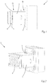
- FIGS. 1 and 2 show views of a holding device 1, wherein a light guide channel 2 is formed in the holding device 1, which extends from a first end section 2a to a second end section 2b of the holding device 1 and opens into a light exit area.
- the first optical element 3 is a collimator.
- the second optical element 4 is a micro-lens array.
- the first end section 2a has a receiving area in which the first optical element 3 is fastened in a form-locking manner.
- the second end section 2b has a stop surface 5 to which the second optical element 4 is attached.
- a heat sink can be attached to the first optical element.
- the first 2a and second end section 2b is formed by the method according to the invention in such a way that when the first optical element 3 is fastened to the first end section 2a and the second optical element 4 is fastened to the second end section 2b, the first 3a and second optical axis 4a are parallel, preferably coaxial, to one another.
- the first optical element 3 comprises the first optical axis 3a and orthogonally to it an optically active surface 3b, from which light, preferably light directed in parallel, can exit.
- the light is emitted in the direction of the second optical element 4 and strikes a second optically active surface 4b of the second optical element 4.
- the light passes through the second optical element 4 and is emitted at a light exit surface 4c.
- the first 3b and second optically active Surface 4b are oriented as parallel as possible to one another.
- the injection molding tool in which the holding device 1 is placed is designed in such a way that a first and second end face, on which the orientation of the first 3 and second optical element 4 is fixed, in the same, in the latter Example in the second, tool half are formed.
Landscapes
- Engineering & Computer Science (AREA)
- Manufacturing & Machinery (AREA)
- Mechanical Engineering (AREA)
- Physics & Mathematics (AREA)
- General Engineering & Computer Science (AREA)
- General Physics & Mathematics (AREA)
- Optics & Photonics (AREA)
- Ophthalmology & Optometry (AREA)
- Health & Medical Sciences (AREA)
- Moulds For Moulding Plastics Or The Like (AREA)
- Business, Economics & Management (AREA)
- Injection Moulding Of Plastics Or The Like (AREA)
- Entrepreneurship & Innovation (AREA)
- Educational Administration (AREA)
- Educational Technology (AREA)
- Theoretical Computer Science (AREA)
Priority Applications (7)
| Application Number | Priority Date | Filing Date | Title |
|---|---|---|---|
| EP19217621.2A EP3838547A1 (fr) | 2019-12-18 | 2019-12-18 | Procédé de fabrication d'un dispositif de maintien |
| US17/775,104 US20220410450A1 (en) | 2019-12-18 | 2020-11-19 | Method for Producing a Holding Device |
| EP20807042.5A EP4076893B1 (fr) | 2019-12-18 | 2020-11-19 | Procédé de fabrication d'un dispositif de maintien |
| PCT/EP2020/082666 WO2021121848A1 (fr) | 2019-12-18 | 2020-11-19 | Procédé de production d'un dispositif de maintien |
| KR1020227014184A KR102725624B1 (ko) | 2019-12-18 | 2020-11-19 | 파지 장치 제조 방법 |
| CN202080087978.XA CN114845851B (zh) | 2019-12-18 | 2020-11-19 | 用于制造保持设备的方法 |
| JP2022537658A JP7366271B2 (ja) | 2019-12-18 | 2020-11-19 | 支持装置の製造方法 |
Applications Claiming Priority (1)
| Application Number | Priority Date | Filing Date | Title |
|---|---|---|---|
| EP19217621.2A EP3838547A1 (fr) | 2019-12-18 | 2019-12-18 | Procédé de fabrication d'un dispositif de maintien |
Publications (1)
| Publication Number | Publication Date |
|---|---|
| EP3838547A1 true EP3838547A1 (fr) | 2021-06-23 |
Family
ID=68965662
Family Applications (2)
| Application Number | Title | Priority Date | Filing Date |
|---|---|---|---|
| EP19217621.2A Withdrawn EP3838547A1 (fr) | 2019-12-18 | 2019-12-18 | Procédé de fabrication d'un dispositif de maintien |
| EP20807042.5A Active EP4076893B1 (fr) | 2019-12-18 | 2020-11-19 | Procédé de fabrication d'un dispositif de maintien |
Family Applications After (1)
| Application Number | Title | Priority Date | Filing Date |
|---|---|---|---|
| EP20807042.5A Active EP4076893B1 (fr) | 2019-12-18 | 2020-11-19 | Procédé de fabrication d'un dispositif de maintien |
Country Status (6)
| Country | Link |
|---|---|
| US (1) | US20220410450A1 (fr) |
| EP (2) | EP3838547A1 (fr) |
| JP (1) | JP7366271B2 (fr) |
| KR (1) | KR102725624B1 (fr) |
| CN (1) | CN114845851B (fr) |
| WO (1) | WO2021121848A1 (fr) |
Families Citing this family (1)
| Publication number | Priority date | Publication date | Assignee | Title |
|---|---|---|---|---|
| US20260041745A1 (en) | 2022-06-09 | 2026-02-12 | Zymedi Co., Ltd. | Novel crs fragment peptide with immunopotentiating activity, and use thereof |
Citations (3)
| Publication number | Priority date | Publication date | Assignee | Title |
|---|---|---|---|---|
| US20110164850A1 (en) * | 2007-08-24 | 2011-07-07 | Wataru Matsuo | Housing-integrated optical semiconductor component and manufacturing method thereof |
| DE202011050563U1 (de) * | 2011-04-12 | 2011-10-19 | Flextronics Automotive Gmbh & Co.Kg | LED-Leuchte |
| EP3409439A1 (fr) * | 2017-05-31 | 2018-12-05 | OSRAM GmbH | Dispositif optique, agencement d'éclairage, phares et procédé |
Family Cites Families (10)
| Publication number | Priority date | Publication date | Assignee | Title |
|---|---|---|---|---|
| JPH07117144A (ja) * | 1993-10-22 | 1995-05-09 | Dainippon Printing Co Ltd | 面光源用導光板の製造方法 |
| JP4578667B2 (ja) | 2000-11-10 | 2010-11-10 | 株式会社ミツバ | 射出成形体の製造方法および射出成形体用金型 |
| JP2006155753A (ja) | 2004-11-29 | 2006-06-15 | Shibata:Kk | レンズホルダ、インサート成形用金型及びインサート成形方法 |
| JP3955065B2 (ja) * | 2005-01-18 | 2007-08-08 | シャープ株式会社 | 光結合器 |
| US20060284327A1 (en) * | 2005-06-16 | 2006-12-21 | Sony Corporation | Optical unit manufacturing method, optical unit, and forming apparatus |
| EP2726782B1 (fr) * | 2011-06-28 | 2016-08-10 | Flextronics Automotive GmbH & Co. KG | Lampe à del |
| JP2014178598A (ja) * | 2013-03-15 | 2014-09-25 | Yazaki Corp | 光素子モジュール |
| JP6202313B2 (ja) * | 2013-09-20 | 2017-09-27 | カシオ計算機株式会社 | 蛍光発光装置及びプロジェクタ |
| US20180162026A1 (en) * | 2016-12-14 | 2018-06-14 | Dura Operating, Llc | Method of embedding electronics in a plastic via transfer from a polymer film |
| CN108973020A (zh) * | 2018-07-02 | 2018-12-11 | 江阴澄云机械有限公司 | 一种用于形成铸模的注塑模具 |
-
2019
- 2019-12-18 EP EP19217621.2A patent/EP3838547A1/fr not_active Withdrawn
-
2020
- 2020-11-19 WO PCT/EP2020/082666 patent/WO2021121848A1/fr not_active Ceased
- 2020-11-19 JP JP2022537658A patent/JP7366271B2/ja active Active
- 2020-11-19 EP EP20807042.5A patent/EP4076893B1/fr active Active
- 2020-11-19 KR KR1020227014184A patent/KR102725624B1/ko active Active
- 2020-11-19 CN CN202080087978.XA patent/CN114845851B/zh active Active
- 2020-11-19 US US17/775,104 patent/US20220410450A1/en not_active Abandoned
Patent Citations (3)
| Publication number | Priority date | Publication date | Assignee | Title |
|---|---|---|---|---|
| US20110164850A1 (en) * | 2007-08-24 | 2011-07-07 | Wataru Matsuo | Housing-integrated optical semiconductor component and manufacturing method thereof |
| DE202011050563U1 (de) * | 2011-04-12 | 2011-10-19 | Flextronics Automotive Gmbh & Co.Kg | LED-Leuchte |
| EP3409439A1 (fr) * | 2017-05-31 | 2018-12-05 | OSRAM GmbH | Dispositif optique, agencement d'éclairage, phares et procédé |
Also Published As
| Publication number | Publication date |
|---|---|
| JP7366271B2 (ja) | 2023-10-20 |
| KR20220070283A (ko) | 2022-05-30 |
| JP2023507456A (ja) | 2023-02-22 |
| KR102725624B1 (ko) | 2024-11-06 |
| WO2021121848A1 (fr) | 2021-06-24 |
| EP4076893A1 (fr) | 2022-10-26 |
| CN114845851B (zh) | 2024-06-25 |
| CN114845851A (zh) | 2022-08-02 |
| US20220410450A1 (en) | 2022-12-29 |
| EP4076893B1 (fr) | 2024-09-04 |
Similar Documents
| Publication | Publication Date | Title |
|---|---|---|
| DE69833150T2 (de) | Vorrichtung zur Herstellung einer faseroptischen Steckerferrule | |
| DE2849975C2 (fr) | ||
| DE69909136T2 (de) | Rapid-prototyping-vorrichtung und rapid-prototyping-methode | |
| EP0194613A2 (fr) | Méthode pour le montage de précision des éléments d'un appareil optique | |
| DE1564354B2 (de) | Metallteil für seriengefertigte Halbleiter-Bauelemente | |
| DE69614303T2 (de) | Verfahren und Vorrichtung zur Herstellung einer faseroptischen Steckeranordnung | |
| DE60303726T2 (de) | Ein Ausrichtungsgerät für optische Fasern und ein optisches Faserarray, das durch Verwendung des Ausrichtungsgeräts hergestellt wird | |
| DE3587180T2 (de) | Faseroptischer Stecker. | |
| DE60119424T2 (de) | Methode zur Herstellung einer faseroptischen Steckerferrule | |
| DE3022485A1 (de) | Lichtsender zur lichtuebertragung durch optische fasern | |
| DE69837129T2 (de) | Faseroptischer Steckerstift | |
| DE4338605C2 (de) | Lichtleiterkupplung für bandförmige Lichtleiterlitzen | |
| EP1237033A2 (fr) | Mélangeur pour l'intégration de lumière en forme de bâton creux et procédé pour sa fabrication | |
| DE69834870T2 (de) | Ausrichtsystem für einen faseroptischen Steckerstift | |
| EP4076893B1 (fr) | Procédé de fabrication d'un dispositif de maintien | |
| DE69212350T2 (de) | Verfahren zum Positionieren und Befestigen von optischen Fasern in einer Reihe von optischen Fasern und mit einer solchen Reihe von optischen Fasern vesehene Kopplungsvorrichtung | |
| EP3943807B1 (fr) | Dispositif d'éclairage pour un phare de véhicule automobile | |
| WO2020025419A1 (fr) | Dispositif d'éclairage pour un véhicule | |
| EP3355097A1 (fr) | Procédé pour la collimation d'un rayonnement lumineux, laser haute puissance et optique de focalisation et procédé de collimation d'un rayonnement lumineux | |
| DE60212480T2 (de) | Giessformanordnung zur Herstellung von mehreren Kontaktlinsen | |
| DE10023221C2 (de) | Optoelektronisches Kopplungselement und Verfahren zu dessen Herstellung | |
| EP3830472B1 (fr) | Dispositif optique pour une phare de véhicule automobile comprenant guides de lumière | |
| DE102016203286A1 (de) | Verfahren zur Montage einer Stiftleiste mit mehreren Stiften an einer Leiterplatte, Leiterplatte mit einer Stiftleiste mit mehreren Stiften und Vorrichtung zur Montage einer Stiftleiste mit mehreren Stiften auf einer Leiterplatte | |
| DE19500214A1 (de) | Verfahren und Vorrichtung zum Umschalten von optischen Signalleitungen | |
| EP3194841A1 (fr) | Dispositif support de guide de lumière, système d'éclairage et procédé pour produire un dispositif support de guide de lumière |
Legal Events
| Date | Code | Title | Description |
|---|---|---|---|
| PUAI | Public reference made under article 153(3) epc to a published international application that has entered the european phase |
Free format text: ORIGINAL CODE: 0009012 |
|
| STAA | Information on the status of an ep patent application or granted ep patent |
Free format text: STATUS: THE APPLICATION HAS BEEN PUBLISHED |
|
| AK | Designated contracting states |
Kind code of ref document: A1 Designated state(s): AL AT BE BG CH CY CZ DE DK EE ES FI FR GB GR HR HU IE IS IT LI LT LU LV MC MK MT NL NO PL PT RO RS SE SI SK SM TR |
|
| STAA | Information on the status of an ep patent application or granted ep patent |
Free format text: STATUS: THE APPLICATION IS DEEMED TO BE WITHDRAWN |
|
| 18D | Application deemed to be withdrawn |
Effective date: 20211224 |