EP3838562B1 - Servogesteuertes ultraschall-schweisssystem und verfahren zum verschweissen mit einem dünnen teil ohne einfallstelle - Google Patents
Servogesteuertes ultraschall-schweisssystem und verfahren zum verschweissen mit einem dünnen teil ohne einfallstelle Download PDFInfo
- Publication number
- EP3838562B1 EP3838562B1 EP20174237.6A EP20174237A EP3838562B1 EP 3838562 B1 EP3838562 B1 EP 3838562B1 EP 20174237 A EP20174237 A EP 20174237A EP 3838562 B1 EP3838562 B1 EP 3838562B1
- Authority
- EP
- European Patent Office
- Prior art keywords
- horn
- thickness
- distal portion
- ultrasonic energy
- exposed surface
- Prior art date
- Legal status (The legal status is an assumption and is not a legal conclusion. Google has not performed a legal analysis and makes no representation as to the accuracy of the status listed.)
- Active
Links
Images


Classifications
-
- B—PERFORMING OPERATIONS; TRANSPORTING
- B29—WORKING OF PLASTICS; WORKING OF SUBSTANCES IN A PLASTIC STATE IN GENERAL
- B29C—SHAPING OR JOINING OF PLASTICS; SHAPING OF MATERIAL IN A PLASTIC STATE, NOT OTHERWISE PROVIDED FOR; AFTER-TREATMENT OF THE SHAPED PRODUCTS, e.g. REPAIRING
- B29C65/00—Joining or sealing of preformed parts, e.g. welding of plastics materials; Apparatus therefor
- B29C65/02—Joining or sealing of preformed parts, e.g. welding of plastics materials; Apparatus therefor by heating, with or without pressure
- B29C65/08—Joining or sealing of preformed parts, e.g. welding of plastics materials; Apparatus therefor by heating, with or without pressure using ultrasonic vibrations
-
- B—PERFORMING OPERATIONS; TRANSPORTING
- B29—WORKING OF PLASTICS; WORKING OF SUBSTANCES IN A PLASTIC STATE IN GENERAL
- B29C—SHAPING OR JOINING OF PLASTICS; SHAPING OF MATERIAL IN A PLASTIC STATE, NOT OTHERWISE PROVIDED FOR; AFTER-TREATMENT OF THE SHAPED PRODUCTS, e.g. REPAIRING
- B29C66/00—General aspects of processes or apparatus for joining preformed parts
- B29C66/006—Preventing damaging, e.g. of the parts to be joined
-
- B—PERFORMING OPERATIONS; TRANSPORTING
- B29—WORKING OF PLASTICS; WORKING OF SUBSTANCES IN A PLASTIC STATE IN GENERAL
- B29C—SHAPING OR JOINING OF PLASTICS; SHAPING OF MATERIAL IN A PLASTIC STATE, NOT OTHERWISE PROVIDED FOR; AFTER-TREATMENT OF THE SHAPED PRODUCTS, e.g. REPAIRING
- B29C66/00—General aspects of processes or apparatus for joining preformed parts
- B29C66/01—General aspects dealing with the joint area or with the area to be joined
- B29C66/05—Particular design of joint configurations
- B29C66/10—Particular design of joint configurations particular design of the joint cross-sections
- B29C66/11—Joint cross-sections comprising a single joint-segment, i.e. one of the parts to be joined comprising a single joint-segment in the joint cross-section
- B29C66/112—Single lapped joints
-
- B—PERFORMING OPERATIONS; TRANSPORTING
- B29—WORKING OF PLASTICS; WORKING OF SUBSTANCES IN A PLASTIC STATE IN GENERAL
- B29C—SHAPING OR JOINING OF PLASTICS; SHAPING OF MATERIAL IN A PLASTIC STATE, NOT OTHERWISE PROVIDED FOR; AFTER-TREATMENT OF THE SHAPED PRODUCTS, e.g. REPAIRING
- B29C66/00—General aspects of processes or apparatus for joining preformed parts
- B29C66/01—General aspects dealing with the joint area or with the area to be joined
- B29C66/05—Particular design of joint configurations
- B29C66/10—Particular design of joint configurations particular design of the joint cross-sections
- B29C66/13—Single flanged joints; Fin-type joints; Single hem joints; Edge joints; Interpenetrating fingered joints; Other specific particular designs of joint cross-sections not provided for in groups B29C66/11 - B29C66/12
- B29C66/131—Single flanged joints, i.e. one of the parts to be joined being rigid and flanged in the joint area
-
- B—PERFORMING OPERATIONS; TRANSPORTING
- B29—WORKING OF PLASTICS; WORKING OF SUBSTANCES IN A PLASTIC STATE IN GENERAL
- B29C—SHAPING OR JOINING OF PLASTICS; SHAPING OF MATERIAL IN A PLASTIC STATE, NOT OTHERWISE PROVIDED FOR; AFTER-TREATMENT OF THE SHAPED PRODUCTS, e.g. REPAIRING
- B29C66/00—General aspects of processes or apparatus for joining preformed parts
- B29C66/01—General aspects dealing with the joint area or with the area to be joined
- B29C66/348—Avoiding melting or weakening of the zone directly next to the joint area, e.g. by cooling
-
- B—PERFORMING OPERATIONS; TRANSPORTING
- B29—WORKING OF PLASTICS; WORKING OF SUBSTANCES IN A PLASTIC STATE IN GENERAL
- B29C—SHAPING OR JOINING OF PLASTICS; SHAPING OF MATERIAL IN A PLASTIC STATE, NOT OTHERWISE PROVIDED FOR; AFTER-TREATMENT OF THE SHAPED PRODUCTS, e.g. REPAIRING
- B29C66/00—General aspects of processes or apparatus for joining preformed parts
- B29C66/40—General aspects of joining substantially flat articles, e.g. plates, sheets or web-like materials; Making flat seams in tubular or hollow articles; Joining single elements to substantially flat surfaces
- B29C66/41—Joining substantially flat articles ; Making flat seams in tubular or hollow articles
- B29C66/43—Joining a relatively small portion of the surface of said articles
-
- B—PERFORMING OPERATIONS; TRANSPORTING
- B29—WORKING OF PLASTICS; WORKING OF SUBSTANCES IN A PLASTIC STATE IN GENERAL
- B29C—SHAPING OR JOINING OF PLASTICS; SHAPING OF MATERIAL IN A PLASTIC STATE, NOT OTHERWISE PROVIDED FOR; AFTER-TREATMENT OF THE SHAPED PRODUCTS, e.g. REPAIRING
- B29C66/00—General aspects of processes or apparatus for joining preformed parts
- B29C66/40—General aspects of joining substantially flat articles, e.g. plates, sheets or web-like materials; Making flat seams in tubular or hollow articles; Joining single elements to substantially flat surfaces
- B29C66/47—Joining single elements to sheets, plates or other substantially flat surfaces
- B29C66/474—Joining single elements to sheets, plates or other substantially flat surfaces said single elements being substantially non-flat
-
- B—PERFORMING OPERATIONS; TRANSPORTING
- B29—WORKING OF PLASTICS; WORKING OF SUBSTANCES IN A PLASTIC STATE IN GENERAL
- B29C—SHAPING OR JOINING OF PLASTICS; SHAPING OF MATERIAL IN A PLASTIC STATE, NOT OTHERWISE PROVIDED FOR; AFTER-TREATMENT OF THE SHAPED PRODUCTS, e.g. REPAIRING
- B29C66/00—General aspects of processes or apparatus for joining preformed parts
- B29C66/50—General aspects of joining tubular articles; General aspects of joining long products, i.e. bars or profiled elements; General aspects of joining single elements to tubular articles, hollow articles or bars; General aspects of joining several hollow-preforms to form hollow or tubular articles
- B29C66/51—Joining tubular articles, profiled elements or bars; Joining single elements to tubular articles, hollow articles or bars; Joining several hollow-preforms to form hollow or tubular articles
- B29C66/53—Joining single elements to tubular articles, hollow articles or bars
- B29C66/532—Joining single elements to the wall of tubular articles, hollow articles or bars
-
- B—PERFORMING OPERATIONS; TRANSPORTING
- B29—WORKING OF PLASTICS; WORKING OF SUBSTANCES IN A PLASTIC STATE IN GENERAL
- B29C—SHAPING OR JOINING OF PLASTICS; SHAPING OF MATERIAL IN A PLASTIC STATE, NOT OTHERWISE PROVIDED FOR; AFTER-TREATMENT OF THE SHAPED PRODUCTS, e.g. REPAIRING
- B29C66/00—General aspects of processes or apparatus for joining preformed parts
- B29C66/50—General aspects of joining tubular articles; General aspects of joining long products, i.e. bars or profiled elements; General aspects of joining single elements to tubular articles, hollow articles or bars; General aspects of joining several hollow-preforms to form hollow or tubular articles
- B29C66/61—Joining from or joining on the inside
-
- B—PERFORMING OPERATIONS; TRANSPORTING
- B29—WORKING OF PLASTICS; WORKING OF SUBSTANCES IN A PLASTIC STATE IN GENERAL
- B29C—SHAPING OR JOINING OF PLASTICS; SHAPING OF MATERIAL IN A PLASTIC STATE, NOT OTHERWISE PROVIDED FOR; AFTER-TREATMENT OF THE SHAPED PRODUCTS, e.g. REPAIRING
- B29C66/00—General aspects of processes or apparatus for joining preformed parts
- B29C66/70—General aspects of processes or apparatus for joining preformed parts characterised by the composition, physical properties or the structure of the material of the parts to be joined; Joining with non-plastics material
- B29C66/72—General aspects of processes or apparatus for joining preformed parts characterised by the composition, physical properties or the structure of the material of the parts to be joined; Joining with non-plastics material characterised by the structure of the material of the parts to be joined
- B29C66/723—General aspects of processes or apparatus for joining preformed parts characterised by the composition, physical properties or the structure of the material of the parts to be joined; Joining with non-plastics material characterised by the structure of the material of the parts to be joined being multi-layered
-
- B—PERFORMING OPERATIONS; TRANSPORTING
- B29—WORKING OF PLASTICS; WORKING OF SUBSTANCES IN A PLASTIC STATE IN GENERAL
- B29C—SHAPING OR JOINING OF PLASTICS; SHAPING OF MATERIAL IN A PLASTIC STATE, NOT OTHERWISE PROVIDED FOR; AFTER-TREATMENT OF THE SHAPED PRODUCTS, e.g. REPAIRING
- B29C66/00—General aspects of processes or apparatus for joining preformed parts
- B29C66/70—General aspects of processes or apparatus for joining preformed parts characterised by the composition, physical properties or the structure of the material of the parts to be joined; Joining with non-plastics material
- B29C66/73—General aspects of processes or apparatus for joining preformed parts characterised by the composition, physical properties or the structure of the material of the parts to be joined; Joining with non-plastics material characterised by the intensive physical properties of the material of the parts to be joined, by the optical properties of the material of the parts to be joined, by the extensive physical properties of the parts to be joined, by the state of the material of the parts to be joined or by the material of the parts to be joined being a thermoplastic or a thermoset
- B29C66/739—General aspects of processes or apparatus for joining preformed parts characterised by the composition, physical properties or the structure of the material of the parts to be joined; Joining with non-plastics material characterised by the intensive physical properties of the material of the parts to be joined, by the optical properties of the material of the parts to be joined, by the extensive physical properties of the parts to be joined, by the state of the material of the parts to be joined or by the material of the parts to be joined being a thermoplastic or a thermoset characterised by the material of the parts to be joined being a thermoplastic or a thermoset
- B29C66/7392—General aspects of processes or apparatus for joining preformed parts characterised by the composition, physical properties or the structure of the material of the parts to be joined; Joining with non-plastics material characterised by the intensive physical properties of the material of the parts to be joined, by the optical properties of the material of the parts to be joined, by the extensive physical properties of the parts to be joined, by the state of the material of the parts to be joined or by the material of the parts to be joined being a thermoplastic or a thermoset characterised by the material of the parts to be joined being a thermoplastic or a thermoset characterised by the material of at least one of the parts being a thermoplastic
- B29C66/73921—General aspects of processes or apparatus for joining preformed parts characterised by the composition, physical properties or the structure of the material of the parts to be joined; Joining with non-plastics material characterised by the intensive physical properties of the material of the parts to be joined, by the optical properties of the material of the parts to be joined, by the extensive physical properties of the parts to be joined, by the state of the material of the parts to be joined or by the material of the parts to be joined being a thermoplastic or a thermoset characterised by the material of the parts to be joined being a thermoplastic or a thermoset characterised by the material of at least one of the parts being a thermoplastic characterised by the materials of both parts being thermoplastics
-
- B—PERFORMING OPERATIONS; TRANSPORTING
- B29—WORKING OF PLASTICS; WORKING OF SUBSTANCES IN A PLASTIC STATE IN GENERAL
- B29C—SHAPING OR JOINING OF PLASTICS; SHAPING OF MATERIAL IN A PLASTIC STATE, NOT OTHERWISE PROVIDED FOR; AFTER-TREATMENT OF THE SHAPED PRODUCTS, e.g. REPAIRING
- B29C66/00—General aspects of processes or apparatus for joining preformed parts
- B29C66/80—General aspects of machine operations or constructions and parts thereof
- B29C66/81—General aspects of the pressing elements, i.e. the elements applying pressure on the parts to be joined in the area to be joined, e.g. the welding jaws or clamps
- B29C66/814—General aspects of the pressing elements, i.e. the elements applying pressure on the parts to be joined in the area to be joined, e.g. the welding jaws or clamps characterised by the design of the pressing elements, e.g. of the welding jaws or clamps
- B29C66/8141—General aspects of the pressing elements, i.e. the elements applying pressure on the parts to be joined in the area to be joined, e.g. the welding jaws or clamps characterised by the design of the pressing elements, e.g. of the welding jaws or clamps characterised by the surface geometry of the part of the pressing elements, e.g. welding jaws or clamps, coming into contact with the parts to be joined
- B29C66/81427—General aspects of the pressing elements, i.e. the elements applying pressure on the parts to be joined in the area to be joined, e.g. the welding jaws or clamps characterised by the design of the pressing elements, e.g. of the welding jaws or clamps characterised by the surface geometry of the part of the pressing elements, e.g. welding jaws or clamps, coming into contact with the parts to be joined comprising a single ridge, e.g. for making a weakening line; comprising a single tooth
- B29C66/81429—General aspects of the pressing elements, i.e. the elements applying pressure on the parts to be joined in the area to be joined, e.g. the welding jaws or clamps characterised by the design of the pressing elements, e.g. of the welding jaws or clamps characterised by the surface geometry of the part of the pressing elements, e.g. welding jaws or clamps, coming into contact with the parts to be joined comprising a single ridge, e.g. for making a weakening line; comprising a single tooth comprising a single tooth
-
- B—PERFORMING OPERATIONS; TRANSPORTING
- B29—WORKING OF PLASTICS; WORKING OF SUBSTANCES IN A PLASTIC STATE IN GENERAL
- B29C—SHAPING OR JOINING OF PLASTICS; SHAPING OF MATERIAL IN A PLASTIC STATE, NOT OTHERWISE PROVIDED FOR; AFTER-TREATMENT OF THE SHAPED PRODUCTS, e.g. REPAIRING
- B29C66/00—General aspects of processes or apparatus for joining preformed parts
- B29C66/80—General aspects of machine operations or constructions and parts thereof
- B29C66/81—General aspects of the pressing elements, i.e. the elements applying pressure on the parts to be joined in the area to be joined, e.g. the welding jaws or clamps
- B29C66/814—General aspects of the pressing elements, i.e. the elements applying pressure on the parts to be joined in the area to be joined, e.g. the welding jaws or clamps characterised by the design of the pressing elements, e.g. of the welding jaws or clamps
- B29C66/8141—General aspects of the pressing elements, i.e. the elements applying pressure on the parts to be joined in the area to be joined, e.g. the welding jaws or clamps characterised by the design of the pressing elements, e.g. of the welding jaws or clamps characterised by the surface geometry of the part of the pressing elements, e.g. welding jaws or clamps, coming into contact with the parts to be joined
- B29C66/81431—General aspects of the pressing elements, i.e. the elements applying pressure on the parts to be joined in the area to be joined, e.g. the welding jaws or clamps characterised by the design of the pressing elements, e.g. of the welding jaws or clamps characterised by the surface geometry of the part of the pressing elements, e.g. welding jaws or clamps, coming into contact with the parts to be joined comprising a single cavity, e.g. a groove
-
- B—PERFORMING OPERATIONS; TRANSPORTING
- B29—WORKING OF PLASTICS; WORKING OF SUBSTANCES IN A PLASTIC STATE IN GENERAL
- B29C—SHAPING OR JOINING OF PLASTICS; SHAPING OF MATERIAL IN A PLASTIC STATE, NOT OTHERWISE PROVIDED FOR; AFTER-TREATMENT OF THE SHAPED PRODUCTS, e.g. REPAIRING
- B29C66/00—General aspects of processes or apparatus for joining preformed parts
- B29C66/80—General aspects of machine operations or constructions and parts thereof
- B29C66/81—General aspects of the pressing elements, i.e. the elements applying pressure on the parts to be joined in the area to be joined, e.g. the welding jaws or clamps
- B29C66/814—General aspects of the pressing elements, i.e. the elements applying pressure on the parts to be joined in the area to be joined, e.g. the welding jaws or clamps characterised by the design of the pressing elements, e.g. of the welding jaws or clamps
- B29C66/8141—General aspects of the pressing elements, i.e. the elements applying pressure on the parts to be joined in the area to be joined, e.g. the welding jaws or clamps characterised by the design of the pressing elements, e.g. of the welding jaws or clamps characterised by the surface geometry of the part of the pressing elements, e.g. welding jaws or clamps, coming into contact with the parts to be joined
- B29C66/81433—General aspects of the pressing elements, i.e. the elements applying pressure on the parts to be joined in the area to be joined, e.g. the welding jaws or clamps characterised by the design of the pressing elements, e.g. of the welding jaws or clamps characterised by the surface geometry of the part of the pressing elements, e.g. welding jaws or clamps, coming into contact with the parts to be joined being toothed, i.e. comprising several teeth or pins, or being patterned
-
- B—PERFORMING OPERATIONS; TRANSPORTING
- B29—WORKING OF PLASTICS; WORKING OF SUBSTANCES IN A PLASTIC STATE IN GENERAL
- B29C—SHAPING OR JOINING OF PLASTICS; SHAPING OF MATERIAL IN A PLASTIC STATE, NOT OTHERWISE PROVIDED FOR; AFTER-TREATMENT OF THE SHAPED PRODUCTS, e.g. REPAIRING
- B29C66/00—General aspects of processes or apparatus for joining preformed parts
- B29C66/80—General aspects of machine operations or constructions and parts thereof
- B29C66/82—Pressure application arrangements, e.g. transmission or actuating mechanisms for joining tools or clamps
- B29C66/824—Actuating mechanisms
- B29C66/8246—Servomechanisms, e.g. servomotors
-
- B—PERFORMING OPERATIONS; TRANSPORTING
- B29—WORKING OF PLASTICS; WORKING OF SUBSTANCES IN A PLASTIC STATE IN GENERAL
- B29C—SHAPING OR JOINING OF PLASTICS; SHAPING OF MATERIAL IN A PLASTIC STATE, NOT OTHERWISE PROVIDED FOR; AFTER-TREATMENT OF THE SHAPED PRODUCTS, e.g. REPAIRING
- B29C66/00—General aspects of processes or apparatus for joining preformed parts
- B29C66/80—General aspects of machine operations or constructions and parts thereof
- B29C66/83—General aspects of machine operations or constructions and parts thereof characterised by the movement of the joining or pressing tools
- B29C66/832—Reciprocating joining or pressing tools
- B29C66/8322—Joining or pressing tools reciprocating along one axis
-
- B—PERFORMING OPERATIONS; TRANSPORTING
- B29—WORKING OF PLASTICS; WORKING OF SUBSTANCES IN A PLASTIC STATE IN GENERAL
- B29C—SHAPING OR JOINING OF PLASTICS; SHAPING OF MATERIAL IN A PLASTIC STATE, NOT OTHERWISE PROVIDED FOR; AFTER-TREATMENT OF THE SHAPED PRODUCTS, e.g. REPAIRING
- B29C66/00—General aspects of processes or apparatus for joining preformed parts
- B29C66/90—Measuring or controlling the joining process
- B29C66/92—Measuring or controlling the joining process by measuring or controlling the pressure, the force, the mechanical power or the displacement of the joining tools
- B29C66/924—Measuring or controlling the joining process by measuring or controlling the pressure, the force, the mechanical power or the displacement of the joining tools by controlling or regulating the pressure, the force, the mechanical power or the displacement of the joining tools
- B29C66/9241—Measuring or controlling the joining process by measuring or controlling the pressure, the force, the mechanical power or the displacement of the joining tools by controlling or regulating the pressure, the force, the mechanical power or the displacement of the joining tools by controlling or regulating the pressure, the force or the mechanical power
-
- B—PERFORMING OPERATIONS; TRANSPORTING
- B29—WORKING OF PLASTICS; WORKING OF SUBSTANCES IN A PLASTIC STATE IN GENERAL
- B29C—SHAPING OR JOINING OF PLASTICS; SHAPING OF MATERIAL IN A PLASTIC STATE, NOT OTHERWISE PROVIDED FOR; AFTER-TREATMENT OF THE SHAPED PRODUCTS, e.g. REPAIRING
- B29C66/00—General aspects of processes or apparatus for joining preformed parts
- B29C66/90—Measuring or controlling the joining process
- B29C66/92—Measuring or controlling the joining process by measuring or controlling the pressure, the force, the mechanical power or the displacement of the joining tools
- B29C66/924—Measuring or controlling the joining process by measuring or controlling the pressure, the force, the mechanical power or the displacement of the joining tools by controlling or regulating the pressure, the force, the mechanical power or the displacement of the joining tools
- B29C66/9261—Measuring or controlling the joining process by measuring or controlling the pressure, the force, the mechanical power or the displacement of the joining tools by controlling or regulating the pressure, the force, the mechanical power or the displacement of the joining tools by controlling or regulating the displacement of the joining tools
-
- B—PERFORMING OPERATIONS; TRANSPORTING
- B29—WORKING OF PLASTICS; WORKING OF SUBSTANCES IN A PLASTIC STATE IN GENERAL
- B29C—SHAPING OR JOINING OF PLASTICS; SHAPING OF MATERIAL IN A PLASTIC STATE, NOT OTHERWISE PROVIDED FOR; AFTER-TREATMENT OF THE SHAPED PRODUCTS, e.g. REPAIRING
- B29C66/00—General aspects of processes or apparatus for joining preformed parts
- B29C66/90—Measuring or controlling the joining process
- B29C66/93—Measuring or controlling the joining process by measuring or controlling the speed
- B29C66/939—Measuring or controlling the joining process by measuring or controlling the speed characterised by specific speed values or ranges
-
- B—PERFORMING OPERATIONS; TRANSPORTING
- B29—WORKING OF PLASTICS; WORKING OF SUBSTANCES IN A PLASTIC STATE IN GENERAL
- B29C—SHAPING OR JOINING OF PLASTICS; SHAPING OF MATERIAL IN A PLASTIC STATE, NOT OTHERWISE PROVIDED FOR; AFTER-TREATMENT OF THE SHAPED PRODUCTS, e.g. REPAIRING
- B29C66/00—General aspects of processes or apparatus for joining preformed parts
- B29C66/90—Measuring or controlling the joining process
- B29C66/95—Measuring or controlling the joining process by measuring or controlling specific variables not covered by groups B29C66/91 - B29C66/94
- B29C66/951—Measuring or controlling the joining process by measuring or controlling specific variables not covered by groups B29C66/91 - B29C66/94 by measuring or controlling the vibration frequency and/or the vibration amplitude of vibrating joining tools, e.g. of ultrasonic welding tools
- B29C66/9513—Measuring or controlling the joining process by measuring or controlling specific variables not covered by groups B29C66/91 - B29C66/94 by measuring or controlling the vibration frequency and/or the vibration amplitude of vibrating joining tools, e.g. of ultrasonic welding tools characterised by specific vibration frequency values or ranges
-
- B—PERFORMING OPERATIONS; TRANSPORTING
- B29—WORKING OF PLASTICS; WORKING OF SUBSTANCES IN A PLASTIC STATE IN GENERAL
- B29C—SHAPING OR JOINING OF PLASTICS; SHAPING OF MATERIAL IN A PLASTIC STATE, NOT OTHERWISE PROVIDED FOR; AFTER-TREATMENT OF THE SHAPED PRODUCTS, e.g. REPAIRING
- B29C66/00—General aspects of processes or apparatus for joining preformed parts
- B29C66/90—Measuring or controlling the joining process
- B29C66/95—Measuring or controlling the joining process by measuring or controlling specific variables not covered by groups B29C66/91 - B29C66/94
- B29C66/951—Measuring or controlling the joining process by measuring or controlling specific variables not covered by groups B29C66/91 - B29C66/94 by measuring or controlling the vibration frequency and/or the vibration amplitude of vibrating joining tools, e.g. of ultrasonic welding tools
- B29C66/9517—Measuring or controlling the joining process by measuring or controlling specific variables not covered by groups B29C66/91 - B29C66/94 by measuring or controlling the vibration frequency and/or the vibration amplitude of vibrating joining tools, e.g. of ultrasonic welding tools characterised by specific vibration amplitude values or ranges
-
- B—PERFORMING OPERATIONS; TRANSPORTING
- B29—WORKING OF PLASTICS; WORKING OF SUBSTANCES IN A PLASTIC STATE IN GENERAL
- B29C—SHAPING OR JOINING OF PLASTICS; SHAPING OF MATERIAL IN A PLASTIC STATE, NOT OTHERWISE PROVIDED FOR; AFTER-TREATMENT OF THE SHAPED PRODUCTS, e.g. REPAIRING
- B29C2795/00—Printing on articles made from plastics or substances in a plastic state
- B29C2795/002—Printing on articles made from plastics or substances in a plastic state before shaping
-
- B—PERFORMING OPERATIONS; TRANSPORTING
- B29—WORKING OF PLASTICS; WORKING OF SUBSTANCES IN A PLASTIC STATE IN GENERAL
- B29C—SHAPING OR JOINING OF PLASTICS; SHAPING OF MATERIAL IN A PLASTIC STATE, NOT OTHERWISE PROVIDED FOR; AFTER-TREATMENT OF THE SHAPED PRODUCTS, e.g. REPAIRING
- B29C66/00—General aspects of processes or apparatus for joining preformed parts
- B29C66/70—General aspects of processes or apparatus for joining preformed parts characterised by the composition, physical properties or the structure of the material of the parts to be joined; Joining with non-plastics material
- B29C66/73—General aspects of processes or apparatus for joining preformed parts characterised by the composition, physical properties or the structure of the material of the parts to be joined; Joining with non-plastics material characterised by the intensive physical properties of the material of the parts to be joined, by the optical properties of the material of the parts to be joined, by the extensive physical properties of the parts to be joined, by the state of the material of the parts to be joined or by the material of the parts to be joined being a thermoplastic or a thermoset
- B29C66/735—General aspects of processes or apparatus for joining preformed parts characterised by the composition, physical properties or the structure of the material of the parts to be joined; Joining with non-plastics material characterised by the intensive physical properties of the material of the parts to be joined, by the optical properties of the material of the parts to be joined, by the extensive physical properties of the parts to be joined, by the state of the material of the parts to be joined or by the material of the parts to be joined being a thermoplastic or a thermoset characterised by the extensive physical properties of the parts to be joined
- B29C66/7352—Thickness, e.g. very thin
- B29C66/73521—Thickness, e.g. very thin of different thickness, i.e. the thickness of one of the parts to be joined being different from the thickness of the other part
-
- B—PERFORMING OPERATIONS; TRANSPORTING
- B29—WORKING OF PLASTICS; WORKING OF SUBSTANCES IN A PLASTIC STATE IN GENERAL
- B29L—INDEXING SCHEME ASSOCIATED WITH SUBCLASS B29C, RELATING TO PARTICULAR ARTICLES
- B29L2031/00—Other particular articles
- B29L2031/30—Vehicles, e.g. ships or aircraft, or body parts thereof
- B29L2031/3044—Bumpers
-
- B—PERFORMING OPERATIONS; TRANSPORTING
- B29—WORKING OF PLASTICS; WORKING OF SUBSTANCES IN A PLASTIC STATE IN GENERAL
- B29L—INDEXING SCHEME ASSOCIATED WITH SUBCLASS B29C, RELATING TO PARTICULAR ARTICLES
- B29L2031/00—Other particular articles
- B29L2031/34—Electrical apparatus, e.g. sparking plugs or parts thereof
- B29L2031/3481—Housings or casings incorporating or embedding electric or electronic elements
Definitions
- Ultrasonic transducers are devices that convert energy into sound, typically in the nature of ultrasonic vibrations--sound waves that have a frequency above the normal range of human hearing.
- One of the most common types of ultrasonic transducers in modern use is the piezoelectric ultrasonic transducer which converts electric signals into mechanical vibrations.
- Piezoelectric materials are materials, traditionally crystalline structures and ceramics, which produce a voltage in response to the application of a mechanical stress. Since this effect also applies in the reverse, a voltage applied across a sample piezoelectric material will produce a mechanical stress within the sample. Suitably designed structures made from these materials can therefore be made that bend, expand, or contract when a current is applied thereto.
- piezo ceramic rings are typically made of a material, such as lead zirconium titanate ceramic (more commonly referred to as "PZT”), which have a proportional relationship between their applied voltage and mechanical strain (e.g., thickness) of the rings.
- PZT lead zirconium titanate ceramic
- the supplied electrical signal is typically provided at a frequency that matches the resonant frequency of the ultrasonic transducer.
- the piezo ceramic rings expand and contract to produce large-amplitude vibrational motion.
- p-p vibrational peak-to-peak
- the electrical signals are often provided as a sine wave by a power supply that regulates the signal so as to produce consistent amplitude mechanical vibrations and protect the mechanical structure against excessive strain or abrupt changes in amplitude or frequency.
- the ultrasonic transducer is connected to an ultrasonic booster and a sonotrode (also commonly called a "horn" in the ultrasonic welding industry), both of which are normally tuned to have a resonant frequency that matches that of the ultrasonic transducer.
- the ultrasonic booster which is structured to permit mounting of the ultrasonic transducer assembly (or “stack” as it is commonly called), is typically a tuned half-wave component that is configured to increase or decrease the vibrational amplitude passed between the converter (transducer) and sonotrode (horn).
- the amount of increase or decrease in amplitude is referred to as "gain.”
- the horn which is oftentimes a tapering metal bar, is structured to augment the oscillation displacement amplitude provided by the ultrasonic transducer and thereby increase or decrease the ultrasonic vibration and distribute it across a desired work area.
- all of the mechanical components used in an ultrasonic transducer assembly must be structured so that they operate at a single resonant frequency that is near or at a desired operating frequency.
- the ultrasonic transducer assembly must often operate with a vibrational motion that is parallel to the primary axis (i.e., the central longitudinal axis) of the assembly.
- the power supply for the stack generally operates as part of a closed-loop feedback system that monitors and regulates the applied voltage and frequency.
- ultrasonic welding technology is highly desirable due to its consistency (particularly when the stack's movement is controlled by a servo-driven motor), speed, weld quality, and other advantages.
- a phenomenon known as "read-through” can occur particularly when one of the parts is thin.
- Read-through in this context is a visual artifact that can be produced during the welding of one side of a thin part, which is visible by the naked eye from the opposite side of the thin part.
- read-through is highly undesirable. This is especially the case when the thin part is painted or has a high-gloss finish, when visible artifacts in the form of read-through become especially pronounced.
- the welding process disturbs the original unblemished state of the thin part in the form of bumps, wavy artifacts, and other perturbations in the exposed surface of the thin part, which are even more pronounced when the thin part has a large, smooth surface.
- an ultrasonic processing device comprising at least one ultrasonic processing unit having an ultrasonic converter and a sonotrode with a sonotrode body extending along an axis with an active area at one axial end which is formed by an axially directed end face and/or by axially directed active elements protruding from the sonotrode body.
- the ultrasonic unit or an anvil unit can be moved relative to one another along a feed path by a feed arrangement.
- An active area of the sonotrode and a workpiece can be brought into engagement so that pressure may be exerted.
- the sonotrode is a radially resonant sonotrode in which an ultrasonic longitudinal vibration introduced by an ultrasonic converter results in an ultrasonic radial vibration in an end of the sonotrode including the active area.
- EP 1 512 518 A1 describes a procedure for attaching a body or fender component to the surface of an associated plastic component such as an ultrasonic sensor with an area having a thin section, preferably 1-3 mm. Small weld zones are created through holes in the back of the associated component. The holes are formed by tangential vibrations created at a distance from the associated component which are then transformed into perpendicular vibrations to weld the two components together. The vibrations are produced by a sonotrode with an excitation end and two vibrating tips in the shape of a tuning fork with bits on their ends.
- US 2014/367018 A1 discloses an ultrasonic welding system with a motion control system that is coupled to and that causes controlled movement of an ultrasonic welding stack in accordance with control inputs that are based on one or more control signals that are received from one or more sensors.
- the motion control system initiates a welding operation, subsequent to which an initial motion delay occurs until a predetermined condition is satisfied.
- the ultrasonic welding stack is caused to move in accordance with a weld profile.
- the ultrasonic welding stack is caused to stop motion and to maintain a stationary position.
- motion of the ultrasonic welding stack is resumed in accordance with the weld profile.
- an ultrasonic welding method for joining a first thermoplastic part and a second thermoplastic part without causing visible read-through on an exposed surface of the second part.
- the method includes: arranging the first part on an inner surface of the second part, the inner surface being opposite the exposed surface, the first part having an interface portion contacting the inner surface; causing a horn of an ultrasonic welding stack to be pressed against the first part by applying ultrasonic energy oscillating at a frequency in a range of 45-70 kHz through the horn, to thereby join the first part and the second part together, the horn having at least one protruding distal portion configured to penetrate through the first part as the ultrasonic energy is imparted through the horn, the at least one protruding distal portion having a length longer than a thickness of the first part, wherein a collapse distance of a weld formed at the interface portion is less than the thickness of the first part, to avoid read-through effects on the exposed surface of the second part.
- the causing the horn to be pressed against the first part can include moving the horn toward the second part at a rate of at least 12 millimeters per second.
- the ultrasonic energy can have an amplitude of at least 50 micrometers peak-to-peak.
- the frequency can be 50 kHz.
- the second part can have a thickness that does not exceed 2.6 millimeters and the exposed surface can be painted.
- the length of the distal portion can be 20% longer than the thickness of the first part.
- the method can further include causing the horn to be retracted from the first part before the at least one protruding distal portion fully penetrates through the thickness of the first part and ceasing application of the ultrasonic energy.
- the at least one protruding distal portion can be a plurality of protruding distal portions, each having the same length. Movement of the horn can be controlled by a servo-driven actuator to ensure that the collapse distance does not exceed the thickness of the first part.
- the at least one protruding distal portion can have, at an end thereof, a square cross-section, or a round cross-section, or an annular cross-section.
- an ultrasonic welding method for joining a first thermoplastic part and a second thermoplastic part without causing visible read-through on an exposed surface of the second part.
- the method includes: arranging the first part on an inner surface of the second part, the inner surface being opposite the exposed surface, the first part having an interface portion contacting the inner surface; responsive to the arranging, moving a horn of an ultrasonic welding stack by a servo-driven motor at a speed of at least 10 millimeters per second while applying ultrasonic energy oscillating at a frequency of 50 kHz through the horn and having an amplitude of at least 50 micrometers peak-to-peak, to thereby join the first part and the second part together, the horn having at least one protruding distal portion configured to penetrate through the first part as the ultrasonic energy is imparted through the horn, the at least one protruding distal portion having a length longer than a thickness of the first part, wherein a collapse distance of a wel
- an ultrasonic welding system for joining a first thermoplastic part and a second thermoplastic part without causing visible read-through on an exposed surface of the second part.
- the system includes: an ultrasonic welding stack including a horn arranged to press a first part to be joined with an inner surface of a second part, the inner surface being opposite the exposed surface, the first part having an interface portion contacting the inner surface, the horn having at least one protruding distal portion; one or more controllers operatively coupled to the ultrasonic welding stack; a servo-driven actuator coupled to the horn to advance and retract the horn under control of the one or more controllers; the one or more controllers operatively coupled to the ultrasonic welding stack and configured to: causing the horn to be pressed against the first part by applying ultrasonic energy oscillating at a frequency in a range of 45-70 kHz through the horn, to thereby join the first part and the second part together, the at least one protruding dis
- the one or more controllers can be further configured to cause the horn to be moved via the servo-driven actuator toward the second part at a rate of at least 12 millimeters per second.
- the ultrasonic energy can have an amplitude of at least 50 micrometers peak-to-peak, and the frequency can be 50 kHz.
- the second part can have a thickness that does not exceed 2.6 millimeters, and the exposed surface can be painted.
- the length of the distal portion cab be 20% longer than the thickness of the first part.
- the one or more controllers can be further configured to cause the horn to be retracted using the servo-driven actuator from the first part before the at least one protruding distal portion fully penetrates through the thickness of the first part and ceasing application of the ultrasonic energy.
- the at least one protruding distal portion cam be a plurality of protruding distal portions, each having the same length.
- the at least one protruding distal portion can have, at an end thereof, a square cross-section, or a round cross-section, or an annular cross-section.
- FIG. 1 is an ultrasonic welding system 100 for joining a first thermoplastic part 102 and a thin, second thermoplastic part 104 without causing visible read-through on an exposed surface 106 (opposite the surface-to-be-welded 105) of the second part 104.
- the system 100 includes an ultrasonic welding stack 110 including a horn 112 arranged to press the first part 102 to be joined with the inner surface 105 of the second part 104.
- the inner surface 105 is opposite the exposed surface 106, which can have a smooth, polished surface, such as one painted with a high gloss finish.
- the second part 104 is a bumper for an automobile.
- the exposed surface 106 is painted to a high-gloss finish and will be installed to a car in a very visible and prominent place on the car. Any read-through caused by welding parts, such as the first part 102 (e.g., a bracket for a PDC (Parking Distance Controller) sensor or imaging camera), to the inner surface 105 of the second part 104 (e.g., bumper) would be readily perceived by the naked eye. As will be discussed in more detail herein, the inventors have discovered solutions to this read-through problem without having to completely reconfigure the pieces of the ultrasonic welding system 100.
- the first part 102 e.g., a bracket for a PDC (Parking Distance Controller) sensor or imaging camera
- the horn 112 which can be seen in better detail in FIGS. 2-4 , includes at least one protruding distal portion 204a (a second portion 204b is also shown, although one or more than two such portions can be present in alternative implementations).
- the distal portions 204a,b can also be called pins and have a pin-like form, albeit with optionally a slight taper (e.g., 20° or 25°) toward a base of the pin where it is integral with the rest of the horn 112.
- An interface portion 202 exists between the first part 102 and the second part 104 when they are brought together to be joined.
- the ultrasonic welding system 100 includes one or more controllers 120 (see FIG. 1 ) operatively coupled to the ultrasonic welding stack 100.
- the one or more controllers can be microelectronic controllers or processors, and can be controlled by any combination of software, firmware, or both to control the ultrasonic welding stack 100, including its movement and the ultrasonic energy that is applied through the horn 112.
- the ultrasonic welding system 100 includes a servo-driven actuator 130, such as a servo motor, which is coupled to the horn 112 to advance and retract the horn 112 under control of the one or more controllers 120. While some of the basic components of an ultrasonic welding system are disclosed herein, the skilled person familiar with ultrasonic welding systems will readily recognize common components and configurations of an ultrasonic welding system, which are too numerous to mention here.
- a servo-driven actuator 130 such as a servo motor
- a key finding by the inventors to completely eliminate the read-through phenomenon involves the configuration of the stack in relation to various parts and their form factors, so it should be understood that components such as power supplies, wiring harnesses, frames, and other cooperating components in various ultrasonic welding systems depending on the myriad applications thereof are not described herein for the sake of brevity and to focus the reader on salient aspects of the inventions.
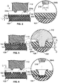
- FIGS. 2-4 using specific dimensions and figures that are not intended to limit the scope of this disclosure. It should be emphasized that certain principles have been discovered to eliminate read-through, but it is convenient to discuss one example of a configuration as a framework to explain the broader concepts of the inventions. To that end, the following data in Table 1 below was used in the setup shown and described in connection with FIGS. 2-4 .
- Table 1 Element Value (exemplary) Thickness of first part 102 (T1) 0.95 - 1 mm Thickness of second part 104 (T2) 2.2 - 2.6 mm Diameter or width of distal portion 204a,b (D) 1 mm Length of distal portion (pin) 204a,b (L) 1.2 mm Maximum collapse distance (d1) 0.8 - 0.9 mm Frequency, f, of ultrasonic energy applied to horn 112 50 kHz Movement speed, v, of stack 110 12 mm/second Amplitude peak-to-peak, A, of ultrasonic energy 50 ⁇ m
- Servo-driven actuators 130 are particularly well-suited for tightly controlled and repeatedly consistent speed and distance movements of the stack 112. However, any other suitable movement-imparting mechanisms in which speed and distance can be consistently and repeatedly controlled can be used instead of a servo-driven actuator 130.
- the interface portion 202 is shown to be relatively flat, when the second part 104 is, e.g., a car bumper, the second part 104 will be curved, so the interface portion 202 may have a small airgap between the first and second parts 102, 104.
- the amplitude of the ultrasonic energy is the amplitude of the ultrasonic energy. Amplitude of about 50 ⁇ m p-p, in combination with a relatively high frequency also produces excellent quality welds with no read-through.
- Another consideration is the collapse distance. The collapse distances should not exceed the thickness, T1, of the first part 102. Ideally, it is within 80% of the thickness, so if T1 is 1mm, then the collapse distance should not exceed 0.8 mm or even 0.9 mm.
- the distal portion 204a,b or pin of the horn 112 should not penetrate all the way through the thickness T1 of the first part 102.
- the horn 112 is advanced in a direction along arrow A toward the first part 102 by the servo-driven actuator 130 at a speed, such as 10 mm/s or 12 mm/s.
- the distal portions 204a,b make contact with the first part 102, and the ultrasonic energy applied through the horn 112 becomes focused through the distal portions 204a,b and begin to melt the first part 102.
- the horn 112 is advanced until, as can be seen in FIG. 3 , a collapse distance is reached, at which time the advancement of the horn 112 is stopped.
- the distal portions 204a,b do not fully penetrate through the thickness T1 of the first part 102.
- Melting of the first part occurs and forms melted portions 220 on the top surface of the first part 102.
- localized melting at the tip or end 218 of the distal portion 204a,b also occurs with contributions from both the first and second parts 102, 104, which can be seen in FIG. 4 .
- a strong weld joint is created at this localized area 210 without causing melting to penetrate through the thickness T2 of the second part 104, thereby avoiding read-through on the exposed surface 106 of the second part 104.
- the length, L, seen in FIG. 4 , of the distal portions 204a,b is about 10% to 20% longer than the thickness, T1, of the first part 102, but does not fully penetrate the thickness T1 of the first part 102.
- FIGS. 5A, 5B, 6A, 6B, 7A, and 7B illustrate different form factors for the distal portions of the horn 112.
- the distal portions 204a,b shown in FIGS. 2-4 can have any of the form factors shown in FIGS. 5A-7B .
- Other form factors are contemplated depending on the application, but read-through effects have been noted to be avoided using these shapes.
- the distal portions 504a, 504b have a square shape or cross-section at an end 518 thereof (see FIG. 5B ). These are shown close together for ease of illustration, but the distal portions 504a,b can be spaced at any constant or varied distance according to any pattern depending on the part to be welded.
- the distal portions can have a taper along its length as can be seen in FIG. 5B .
- the distal portions 604a,b have a round shape or cross-section at an end 618 thereof (see FIG. 6B ).
- the distal portions 704a,b have an annular shape or cross-section at end 718 ( FIG. 7B ) thereof.
- a recess 740 forms the annular shape and allows molten material from the first part to melt within the recess 740 as the horn 112 is advanced through the thickness of the first part.
- the thickness of the annular portion of the horn 112 can be 0.25 mm
- the inner diameter of the annular portion can be 2 mm
- a height of the recess 740 can be 0.5 mm.
- the distal portions 704a,b can have a slight taper, e.g., 8°.
- FIG. 8 illustrates an example where the first part 800 is a park distance control (PDC) sensor to be welded to a second part 104, which in this example can be a bumper for an automobile.
- the horn 112 has multiple distal portions 802a,b,c,d,e,f,g,h,i,j,k,l arranged about a periphery of a cavity 850 of the horn 112.
- the cavity 850 receives a bracket portion of the PDC sensor 800 so that the distal portions 802a-1 can be simultaneously moved through the first part 102 to create multiple weld joints simultaneously relative to the second part 104 without causing any read-through on the exposed surface 106 of the second part 104.
- FIG. 9 shows the horn 112 fully extended until the desired collapse distance has been reached, which as described above does not exceed the thickness of the portion of the first part 104 that is welded to respective portion of the second part 102.
- FIG. 10 is an example flow chart illustrating an ultrasonic welding method 1000 for joining two thermoplastic parts together without causing visible read-through on an exposed surface of the second part.
- the method 1000 includes arranging the first part (e.g., 102) on the second, thin part (e.g., 104) (1002).
- the horn e.g., 112 is pressed against the first part (1004).
- Ultrasonic energy is applied through the horn while advancing the horn toward the second part (1006).
- the distal portion of the horn advances through the first part until it is stopped before the horn fully penetrates the first part.
- the horn is retracted from the first part before the horn fully penetrates the first part (1008). Stated differently, the collapse distance of distal portion is less than a thickness of the first part.
- FIG. 11 is an example flow chart illustrating an ultrasonic welding method 1100 for joining two thermoplastic parts together without causing visible read-through on an exposed surface of the second part (which is opposite the surface of the second part onto which the first part is to be joined).
- the method 1100 includes arranging the first part (e.g., 102) on the second part (e.g., 104) (1102).
- the servo-driven stack e.g., 110
- the ultrasonic energy e.g., 50 kHz at 50 ⁇ m
- the horn continues to advance through the first part (1108) before it fully penetrates through the thickness of the first part.
- the advancement of the horn is stopped before the horn fully penetrates the first part (1110).
- Application of the ultrasonic energy is stopped (1112).
- the horn is retracted from the first part before fully penetrating the first part, leaving a strong weld joint between the two parts without any read-through on the other exposed surface of the second part.
- the parts here have been shown in the drawings as having a generally flat interface, they can have non-flat interfaces, such as curved, wavy, or the like.
- the bumper is curved, so the PDC sensor bracket, which has a flat surface, needs to be welded to a gently curved surface at multiple points around the bracket flange.
- the horn can have any number of pins or distal portions that penetrate into the first part, and they can be arranged according to any pattern suitable for the part to be welded.
Landscapes
- Engineering & Computer Science (AREA)
- Mechanical Engineering (AREA)
- Lining Or Joining Of Plastics Or The Like (AREA)
Claims (15)
- Ultraschall-Schweißverfahren zum Verbinden eines ersten thermoplastischen Teils (102) und eines zweiten thermoplastischen Teils (104), ohne ein sichtbares Durchschlagen auf einer freiliegenden Oberfläche (106) des zweiten Teils (104) zu verursachen, umfassend:Anordnen des ersten Teils (102) auf einer inneren Oberfläche (105) des zweiten Teils (104), wobei die innere Oberfläche (105) entgegengesetzt zur freiliegenden Oberfläche (106) ist, wobei das erste Teil (102) einen Schnittstellenabschnitt aufweist, der die innere Oberfläche (105) berührt;Bewirken, dass ein Horn (112) eines Ultraschall-Schwinggebildes (110) gegen das erste Teil (102) gedrückt wird, indem Ultraschallenergie angewandt wird, die mit einer Frequenz in einem Bereich von 45 bis 70 kHz durch das Horn (112) schwingt, sodass dadurch das erste Teil (102) und das zweite Teil (104) miteinander verbunden werden, wobei das Horn (112) mindestens einen hervorstehenden distalen Abschnitt (204a, 204b, 504a, 504b, 604a, 604b, 704a, 704b, 802a bis 8021) aufweist, der so ausgestaltet ist, dass er das erste Teil (102) durchdringt, während die Ultraschallenergie durch das Horn (112) übertragen wird, wobei der mindestens eine hervorstehende distale Abschnitt (204a, 204b, 504a, 504b, 604a, 604b, 704a, 704b, 802a bis 8021) eine Länge aufweist, die länger als eine Dicke des ersten Teils (102) ist, wobei ein Setzweg (d1) einer an dem Schnittstellenabschnitt gebildeten Schweißnaht kleiner als die Dicke des ersten Teils (102) ist, sodass Durchschlageffekte auf der freiliegenden Oberfläche (106) des zweiten Teils (104) vermieden werden.
- Verfahren nach Anspruch 1, wobei das Bewirken, dass das Horn (112) gegen das erste Teil (102) gedrückt wird, das Bewegen des Horns (112) in Richtung des zweiten Teils (104) mit einer Geschwindigkeit von mindestens 12 Millimetern pro Sekunde umfasst.
- Verfahren nach Anspruch 1, wobei die Ultraschallenergie eine Amplitude von mindestens 50 Mikrometern von Spitze zu Spitze aufweist.
- Verfahren nach Anspruch 2, wobei die Ultraschallenergie eine Amplitude von mindestens 50 Mikrometern von Spitze zu Spitze aufweist und die Frequenz 50 kHz beträgt.
- Verfahren nach Anspruch 1, wobei das zweite Teil (104) eine Dicke aufweist, die 2,6 Millimeter nicht überschreitet, und die freiliegende Oberfläche (106) lackiert ist.
- Verfahren nach Anspruch 1, wobei die Länge (L) des distalen Abschnitts (204a, 204b, 504a, 504b, 604a, 604b, 704a, 704b, 802a bis 8021) 20 % länger als die Dicke des ersten Teils (102) ist.
- Verfahren nach Anspruch 1, das ferner das Zurückziehen des Horns (112) von dem ersten Teil (102), bevor der mindestens eine hervorstehende distale Abschnitt (204a, 204b, 504a, 504b, 604a, 604b, 704a, 704b, 802a bis 8021) vollständig durch die Dicke des ersten Teils (102) dringt, und das Beenden der Anwendung der Ultraschallenergie umfasst.
- Verfahren nach Anspruch 1, wobei der mindestens eine hervorstehende distale Abschnitt durch eine Vielzahl von hervorstehenden distalen Abschnitten (204a, 204b, 504a, 504b, 604a, 604b, 704a, 704b, 802a bis 8021) gebildet ist, die jeweils die gleiche Länge (L) aufweisen.
- Verfahren nach Anspruch 1, wobei die Bewegung des Horns (112) so durch einen servogesteuerten Aktor (130) gesteuert wird, dass sichergestellt wird, dass der Setzweg die Dicke des ersten Teils (102) nicht überschreitet.
- Verfahren nach Anspruch 1, ferner umfassend:als Reaktion auf das Anordnen, dass das Bewirken, dass das Horn (112) durch Anwenden von Ultraschallenergie gegen das erste Teil (102) gedrückt wird, das Bewegen des Horns (112) des Ultraschall-Schwinggebildes (110) durch einen servogesteuerten Motor bei einer Geschwindigkeit von mindestens 10 Millimetern pro Sekunde bei gleichzeitigem Anwenden von Ultraschallenergie , die mit einer Frequenz von 50 kHz durch das Horn schwingt, und eine Amplitude von mindestens 50 Mikrometern von Spitze zu Spitze aufweist, einschließt;Anhalten der Bewegung des Horns (112), bevor der mindestens eine hervorstehende Abschnitt (204a, 204b, 504a, 504b, 604a, 604b, 704a, 704b, 802a bis 8021) vollständig die Dicke des ersten Teils (102) durchdrungen hat;als Reaktion auf das Anhalten, Zurückziehen des Horns (112) von dem ersten Teil (102), bevor der mindestens eine hervorstehende distale Abschnitt (204a, 204b, 504a, 504b, 604a, 604b, 704a, 704b, 802a bis 8021) vollständig die Dicke des ersten Teils (102) durchdringt; undBeenden der Anwendung der Ultraschallenergie zum Herstellen des mit dem zweiten Teil (104) verbundenen ersten Teils (102) ohne irgendwelche sichtbaren Durchschlageffekte auf der freiliegenden Oberfläche (106) des zweiten Teils (104).
- Ultraschall-Schweißsystem zum Verbinden eines ersten thermoplastischen Teils (102) und eines zweiten thermoplastischen Teils (104), ohne dass ein sichtbares Durchschlagen auf einer freiliegenden Oberfläche (106) des zweiten Teils (104) verursacht wird, wobei das System Folgendes umfasst:das erste Teil (102);das zweite Teil (104);ein Ultraschall-Schwinggebilde (110), das ein Horn (112) umfasst, der so eingerichtet ist, dass er das erste Teil (102), das mit einer inneren Oberfläche (105) des zweiten Teils (104) zu verbinden ist, drückt, wobei die innere Oberfläche (105) entgegengesetzt zur freiliegenden Oberfläche (106) ist, wobei das erste Teil (102) einen Schnittstellenabschnitt (202) aufweist, der die innere Oberfläche (105) berührt, wobei das Horn (112) mindestens einen hervorstehenden distalen Abschnitt (204a, 204b, 504a, 504b, 604a, 604b, 704a, 704b, 802a bis 8021) aufweist;eine oder mehrere Steuereinrichtungen (120), die betriebsfähig an das Ultraschall-Schwinggebilde (110) gekoppelt ist bzw. sind;einen servogesteuerten Aktuator (130), der so an das Horn (112) gekoppelt ist, dass das Horn (112) unter der Steuerung der einen oder der mehreren Steuereinrichtungen (120) vorgeschoben und zurückgezogen wird;wobei die eine oder die mehreren Steuereinrichtungen (120) betriebsfähig an das Ultraschall-Schwinggebilde (110) gekoppelt ist bzw. sind und ausgestaltet ist bzw. sind zum:
Bewirken, dass das Horn (112) gegen den ersten Teil (102) gedrückt wird, indem Ultraschallenergie angewandt wird, die bei einer Frequenz in einem Bereich von 45 bis 70 kHz durch das Horn (112) schwingt, sodass dadurch das erste Teil (102) und das zweite Teil (104) miteinander verbunden werden, wobei der mindestens eine hervorstehende distale Abschnitt (204a, 204b, 504a, 504b, 604a, 604b, 704a, 704b, 802a bis 802l) dazu ausgestaltet ist, das erste Teil (102) zu durchdringen, während die Ultraschallenergie durch das Horn (112) weitergegeben wird, wobei der mindestens eine hervorstehende distale Abschnitt (204a, 204b, 504a, 504b, 604a, 604b, 704a, 704b, 802a bis 8021) eine Länge (L) aufweist, die länger als eine Dicke des ersten Teils (102) ist, wobei ein Setzweg (d1) einer an dem Schnittstellenabschnitt gebildeten Schweißnaht kleiner als die Dicke des ersten Teils (102) ist, sodass Durchschlageffekte auf der freiliegenden Oberfläche (106) des zweiten Teils (104) vermieden werden. - System nach Anspruch 11, wobei die eine oder die mehreren Steuereinrichtungen (120) ferner dazu ausgestaltet ist bzw. sind, das Horn (112) über den servogesteuerten Aktor mit einer Geschwindigkeit von mindestens 12 Millimetern pro Sekunde hin zu dem zweiten Teil (104) zu bewegen.
- System nach Anspruch 11, wobei die Länge (L) des distalen Abschnitts (204a, 204b, 504a, 504b, 604a, 604b, 704a, 704b, 802a bis 8021) 20 % länger als die Dicke des ersten Teils (102) ist.
- System nach Anspruch 11, wobei die eine oder mehreren Steuereinrichtungen (120) dazu ausgestaltet ist bzw. sind, zu veranlassen, dass das Horn (112) unter Verwendung des servogesteuerten Aktors von dem ersten Teil (102) zurückgezogen wird, bevor der mindestens eine hervorstehende distale Abschnitt (204a, 204b, 504a, 504b, 604a, 604b, 704a, 704b, 802a bis 8021) vollständig die Dicke des ersten Teils (102) durchdringt und das Anwenden der Ultraschallenergie beendet wird.
- System nach Anspruch 11, wobei der mindestens eine hervorstehende distale Abschnitt durch eine Vielzahl von hervorstehenden distalen Abschnitten (204a, 204b, 504a, 504b, 604a, 604b, 704a, 704b, 802a bis 8021) gebildet ist, die jeweils die gleiche Länge (L) aufweisen.
Applications Claiming Priority (1)
| Application Number | Priority Date | Filing Date | Title |
|---|---|---|---|
| US16/723,396 US10710311B1 (en) | 2019-12-20 | 2019-12-20 | Servo-driven ultrasonic welding system and method for welding to a thin part without read-through |
Publications (2)
| Publication Number | Publication Date |
|---|---|
| EP3838562A1 EP3838562A1 (de) | 2021-06-23 |
| EP3838562B1 true EP3838562B1 (de) | 2022-10-26 |
Family
ID=70682665
Family Applications (1)
| Application Number | Title | Priority Date | Filing Date |
|---|---|---|---|
| EP20174237.6A Active EP3838562B1 (de) | 2019-12-20 | 2020-05-12 | Servogesteuertes ultraschall-schweisssystem und verfahren zum verschweissen mit einem dünnen teil ohne einfallstelle |
Country Status (5)
| Country | Link |
|---|---|
| US (2) | US10710311B1 (de) |
| EP (1) | EP3838562B1 (de) |
| ES (1) | ES2932969T3 (de) |
| PL (1) | PL3838562T3 (de) |
| WO (1) | WO2021127063A1 (de) |
Families Citing this family (4)
| Publication number | Priority date | Publication date | Assignee | Title |
|---|---|---|---|---|
| US10710311B1 (en) | 2019-12-20 | 2020-07-14 | Dukane Ias, Llc | Servo-driven ultrasonic welding system and method for welding to a thin part without read-through |
| DE102020200184A1 (de) * | 2020-01-09 | 2021-07-15 | Magna Exteriors (Bohemia) s.r.o. | Verfahren zum Ultraschallverschweißen zweier Kunststoffkomponenten und dadurch hergestellte Kunststoffbauteile |
| KR102833462B1 (ko) * | 2021-10-21 | 2025-07-14 | 주식회사 엘지에너지솔루션 | 용접 압력 제어 시스템, 이를 이용하는 용접 압력 제어 방법 및 이를 이용하는 용접대상물 두께 측정방법 |
| US12090709B1 (en) | 2023-10-18 | 2024-09-17 | Dukane Ias, Llc | Apparatus and a method for targeted ultrasonic melt-forming or staking |
Family Cites Families (9)
| Publication number | Priority date | Publication date | Assignee | Title |
|---|---|---|---|---|
| US4534818A (en) * | 1983-12-22 | 1985-08-13 | Frito-Lay, Inc. | Method and apparatus for ultrasonic sealing |
| US4767492A (en) * | 1986-04-18 | 1988-08-30 | Pola Chemical Industries, Inc. | Ultrasonic fuse-bonding sealing apparatus with improved contact surfaces |
| FR2859409B1 (fr) * | 2003-09-08 | 2006-06-16 | Plastic Omnium Cie | Ensemble d'une piece d'aspect d'un vehicule automobile et d'une autre piece solidarisee a la piece d'aspect par fusion de matiere et procede d'assemblage de ces pieces |
| US9144937B2 (en) * | 2006-05-08 | 2015-09-29 | Dukane Corporation | Ultrasonic press using servo motor with delayed motion |
| DE102006062149A1 (de) | 2006-06-13 | 2007-12-20 | Plastal Gmbh | Distanzschweißen |
| US9487317B2 (en) * | 2010-10-26 | 2016-11-08 | Rinco Ultrasonics USA, Inc. | Sonotrode and anvil energy director grids for narrow/complex ultrasonic welds of improved durability |
| WO2012109541A1 (en) * | 2011-02-10 | 2012-08-16 | Magna International Inc. | Bumper made using a resistive implant welding process |
| DE202017104190U1 (de) * | 2017-07-13 | 2018-10-16 | PP-Tech GmbH | Ultraschallbearbeitungseinrichtung und radial-resonante Ultraschallsonotrode |
| US10710311B1 (en) | 2019-12-20 | 2020-07-14 | Dukane Ias, Llc | Servo-driven ultrasonic welding system and method for welding to a thin part without read-through |
-
2019
- 2019-12-20 US US16/723,396 patent/US10710311B1/en active Active
-
2020
- 2020-05-12 PL PL20174237.6T patent/PL3838562T3/pl unknown
- 2020-05-12 ES ES20174237T patent/ES2932969T3/es active Active
- 2020-05-12 EP EP20174237.6A patent/EP3838562B1/de active Active
- 2020-06-10 US US16/897,962 patent/US11407181B2/en active Active
- 2020-12-16 WO PCT/US2020/065444 patent/WO2021127063A1/en not_active Ceased
Also Published As
| Publication number | Publication date |
|---|---|
| US11407181B2 (en) | 2022-08-09 |
| US20210187866A1 (en) | 2021-06-24 |
| ES2932969T3 (es) | 2023-01-30 |
| WO2021127063A1 (en) | 2021-06-24 |
| US10710311B1 (en) | 2020-07-14 |
| PL3838562T3 (pl) | 2023-03-20 |
| EP3838562A1 (de) | 2021-06-23 |
Similar Documents
| Publication | Publication Date | Title |
|---|---|---|
| EP3838562B1 (de) | Servogesteuertes ultraschall-schweisssystem und verfahren zum verschweissen mit einem dünnen teil ohne einfallstelle | |
| CN112622281B (zh) | 用于聚合物和聚合物复合材料的超声焊接的设备 | |
| EP1113916B1 (de) | Rotierendes akustisches horn mit einer hülse | |
| US10807314B1 (en) | Ultrasonic welding systems and methods using dual, synchronized horns on opposite sides of parts to be joined | |
| US8272424B2 (en) | System for enhancing sonotrode performance in ultrasonic additive manufacturing applications | |
| EP0909224B1 (de) | Gestapeltes rotierendes akustisches horn | |
| EP3807080B1 (de) | Verfahren zur bestimmung einer schmelzschichtdicke verbunden mit einer vorbestimmten schweissnahtfestigkeit basierend auf einer korrelation dazwischen | |
| CN112888553B (zh) | 用于焊接物理变化部件的自动超声挤压系统和方法 | |
| US9688017B2 (en) | Vibration welders with high frequency vibration, position motion control, and delayed weld motion | |
| JPS6233065B2 (de) | ||
| US20200101519A1 (en) | Ultrasonically Assisted Self-Piercing Riveting | |
| CA2813846A1 (en) | System and method for mounting ultrasonic tools | |
| JP6701643B2 (ja) | 線形摩擦接合装置及び線形摩擦接合方法 | |
| KR20240038802A (ko) | 재료들의 초음파 통합 | |
| KR20210126124A (ko) | 알루미늄재의 스폿 용접 방법 및 알루미늄재 | |
| JP7255900B2 (ja) | 超音波接合方法 | |
| JP4047540B2 (ja) | 中空振動ホーン | |
| JP7492391B2 (ja) | 超音波接合装置、超音波接合装置のチップ部材及びチップ部材の取付方法 | |
| GB2570778A (en) | Setting unit for a self-piercing rivet device, self-piercing rivet device and method for connecting component parts | |
| JP7219495B2 (ja) | 超音波接合装置 | |
| JPH0585291B2 (de) | ||
| JP7285005B2 (ja) | 機械振動加工装置及び機械振動加工方法 | |
| JP2023111424A (ja) | 構造体の製造方法 | |
| JP5206465B2 (ja) | 金属部材の接合方法及び金属部材の接合装置 | |
| WO2025110173A1 (ja) | 超音波接合装置 |
Legal Events
| Date | Code | Title | Description |
|---|---|---|---|
| PUAI | Public reference made under article 153(3) epc to a published international application that has entered the european phase |
Free format text: ORIGINAL CODE: 0009012 |
|
| STAA | Information on the status of an ep patent application or granted ep patent |
Free format text: STATUS: THE APPLICATION HAS BEEN PUBLISHED |
|
| AK | Designated contracting states |
Kind code of ref document: A1 Designated state(s): AL AT BE BG CH CY CZ DE DK EE ES FI FR GB GR HR HU IE IS IT LI LT LU LV MC MK MT NL NO PL PT RO RS SE SI SK SM TR |
|
| STAA | Information on the status of an ep patent application or granted ep patent |
Free format text: STATUS: REQUEST FOR EXAMINATION WAS MADE |
|
| 17P | Request for examination filed |
Effective date: 20211222 |
|
| RBV | Designated contracting states (corrected) |
Designated state(s): AL AT BE BG CH CY CZ DE DK EE ES FI FR GB GR HR HU IE IS IT LI LT LU LV MC MK MT NL NO PL PT RO RS SE SI SK SM TR |
|
| RIC1 | Information provided on ipc code assigned before grant |
Ipc: B29L 31/34 20060101ALN20220329BHEP Ipc: B29L 31/30 20060101ALN20220329BHEP Ipc: B29K 101/12 20060101ALN20220329BHEP Ipc: B29C 65/08 20060101AFI20220329BHEP |
|
| GRAP | Despatch of communication of intention to grant a patent |
Free format text: ORIGINAL CODE: EPIDOSNIGR1 |
|
| STAA | Information on the status of an ep patent application or granted ep patent |
Free format text: STATUS: GRANT OF PATENT IS INTENDED |
|
| INTG | Intention to grant announced |
Effective date: 20220509 |
|
| RIN1 | Information on inventor provided before grant (corrected) |
Inventor name: KLINSTEIN, LEO Inventor name: BENDA, ARNOST Inventor name: VIZEK, JIRI Inventor name: VASKO, PETR |
|
| GRAS | Grant fee paid |
Free format text: ORIGINAL CODE: EPIDOSNIGR3 |
|
| GRAA | (expected) grant |
Free format text: ORIGINAL CODE: 0009210 |
|
| STAA | Information on the status of an ep patent application or granted ep patent |
Free format text: STATUS: THE PATENT HAS BEEN GRANTED |
|
| AK | Designated contracting states |
Kind code of ref document: B1 Designated state(s): AL AT BE BG CH CY CZ DE DK EE ES FI FR GB GR HR HU IE IS IT LI LT LU LV MC MK MT NL NO PL PT RO RS SE SI SK SM TR |
|
| REG | Reference to a national code |
Ref country code: GB Ref legal event code: FG4D |
|
| REG | Reference to a national code |
Ref country code: CH Ref legal event code: EP |
|
| REG | Reference to a national code |
Ref country code: AT Ref legal event code: REF Ref document number: 1526754 Country of ref document: AT Kind code of ref document: T Effective date: 20221115 |
|
| REG | Reference to a national code |
Ref country code: DE Ref legal event code: R096 Ref document number: 602020005819 Country of ref document: DE |
|
| REG | Reference to a national code |
Ref country code: IE Ref legal event code: FG4D |
|
| REG | Reference to a national code |
Ref country code: NL Ref legal event code: FP |
|
| REG | Reference to a national code |
Ref country code: ES Ref legal event code: FG2A Ref document number: 2932969 Country of ref document: ES Kind code of ref document: T3 Effective date: 20230130 |
|
| REG | Reference to a national code |
Ref country code: LT Ref legal event code: MG9D |
|
| REG | Reference to a national code |
Ref country code: AT Ref legal event code: MK05 Ref document number: 1526754 Country of ref document: AT Kind code of ref document: T Effective date: 20221026 |
|
| PG25 | Lapsed in a contracting state [announced via postgrant information from national office to epo] |
Ref country code: SE Free format text: LAPSE BECAUSE OF FAILURE TO SUBMIT A TRANSLATION OF THE DESCRIPTION OR TO PAY THE FEE WITHIN THE PRESCRIBED TIME-LIMIT Effective date: 20221026 Ref country code: PT Free format text: LAPSE BECAUSE OF FAILURE TO SUBMIT A TRANSLATION OF THE DESCRIPTION OR TO PAY THE FEE WITHIN THE PRESCRIBED TIME-LIMIT Effective date: 20230227 Ref country code: NO Free format text: LAPSE BECAUSE OF FAILURE TO SUBMIT A TRANSLATION OF THE DESCRIPTION OR TO PAY THE FEE WITHIN THE PRESCRIBED TIME-LIMIT Effective date: 20230126 Ref country code: LT Free format text: LAPSE BECAUSE OF FAILURE TO SUBMIT A TRANSLATION OF THE DESCRIPTION OR TO PAY THE FEE WITHIN THE PRESCRIBED TIME-LIMIT Effective date: 20221026 Ref country code: FI Free format text: LAPSE BECAUSE OF FAILURE TO SUBMIT A TRANSLATION OF THE DESCRIPTION OR TO PAY THE FEE WITHIN THE PRESCRIBED TIME-LIMIT Effective date: 20221026 Ref country code: AT Free format text: LAPSE BECAUSE OF FAILURE TO SUBMIT A TRANSLATION OF THE DESCRIPTION OR TO PAY THE FEE WITHIN THE PRESCRIBED TIME-LIMIT Effective date: 20221026 |
|
| PG25 | Lapsed in a contracting state [announced via postgrant information from national office to epo] |
Ref country code: RS Free format text: LAPSE BECAUSE OF FAILURE TO SUBMIT A TRANSLATION OF THE DESCRIPTION OR TO PAY THE FEE WITHIN THE PRESCRIBED TIME-LIMIT Effective date: 20221026 Ref country code: LV Free format text: LAPSE BECAUSE OF FAILURE TO SUBMIT A TRANSLATION OF THE DESCRIPTION OR TO PAY THE FEE WITHIN THE PRESCRIBED TIME-LIMIT Effective date: 20221026 Ref country code: IS Free format text: LAPSE BECAUSE OF FAILURE TO SUBMIT A TRANSLATION OF THE DESCRIPTION OR TO PAY THE FEE WITHIN THE PRESCRIBED TIME-LIMIT Effective date: 20230226 Ref country code: HR Free format text: LAPSE BECAUSE OF FAILURE TO SUBMIT A TRANSLATION OF THE DESCRIPTION OR TO PAY THE FEE WITHIN THE PRESCRIBED TIME-LIMIT Effective date: 20221026 Ref country code: GR Free format text: LAPSE BECAUSE OF FAILURE TO SUBMIT A TRANSLATION OF THE DESCRIPTION OR TO PAY THE FEE WITHIN THE PRESCRIBED TIME-LIMIT Effective date: 20230127 |
|
| REG | Reference to a national code |
Ref country code: DE Ref legal event code: R097 Ref document number: 602020005819 Country of ref document: DE |
|
| PG25 | Lapsed in a contracting state [announced via postgrant information from national office to epo] |
Ref country code: SM Free format text: LAPSE BECAUSE OF FAILURE TO SUBMIT A TRANSLATION OF THE DESCRIPTION OR TO PAY THE FEE WITHIN THE PRESCRIBED TIME-LIMIT Effective date: 20221026 Ref country code: RO Free format text: LAPSE BECAUSE OF FAILURE TO SUBMIT A TRANSLATION OF THE DESCRIPTION OR TO PAY THE FEE WITHIN THE PRESCRIBED TIME-LIMIT Effective date: 20221026 Ref country code: EE Free format text: LAPSE BECAUSE OF FAILURE TO SUBMIT A TRANSLATION OF THE DESCRIPTION OR TO PAY THE FEE WITHIN THE PRESCRIBED TIME-LIMIT Effective date: 20221026 Ref country code: DK Free format text: LAPSE BECAUSE OF FAILURE TO SUBMIT A TRANSLATION OF THE DESCRIPTION OR TO PAY THE FEE WITHIN THE PRESCRIBED TIME-LIMIT Effective date: 20221026 |
|
| PG25 | Lapsed in a contracting state [announced via postgrant information from national office to epo] |
Ref country code: SK Free format text: LAPSE BECAUSE OF FAILURE TO SUBMIT A TRANSLATION OF THE DESCRIPTION OR TO PAY THE FEE WITHIN THE PRESCRIBED TIME-LIMIT Effective date: 20221026 Ref country code: AL Free format text: LAPSE BECAUSE OF FAILURE TO SUBMIT A TRANSLATION OF THE DESCRIPTION OR TO PAY THE FEE WITHIN THE PRESCRIBED TIME-LIMIT Effective date: 20221026 |
|
| PLBE | No opposition filed within time limit |
Free format text: ORIGINAL CODE: 0009261 |
|
| STAA | Information on the status of an ep patent application or granted ep patent |
Free format text: STATUS: NO OPPOSITION FILED WITHIN TIME LIMIT |
|
| 26N | No opposition filed |
Effective date: 20230727 |
|
| PG25 | Lapsed in a contracting state [announced via postgrant information from national office to epo] |
Ref country code: SI Free format text: LAPSE BECAUSE OF FAILURE TO SUBMIT A TRANSLATION OF THE DESCRIPTION OR TO PAY THE FEE WITHIN THE PRESCRIBED TIME-LIMIT Effective date: 20221026 |
|
| PG25 | Lapsed in a contracting state [announced via postgrant information from national office to epo] |
Ref country code: MC Free format text: LAPSE BECAUSE OF FAILURE TO SUBMIT A TRANSLATION OF THE DESCRIPTION OR TO PAY THE FEE WITHIN THE PRESCRIBED TIME-LIMIT Effective date: 20221026 |
|
| REG | Reference to a national code |
Ref country code: BE Ref legal event code: MM Effective date: 20230531 |
|
| PG25 | Lapsed in a contracting state [announced via postgrant information from national office to epo] |
Ref country code: MC Free format text: LAPSE BECAUSE OF FAILURE TO SUBMIT A TRANSLATION OF THE DESCRIPTION OR TO PAY THE FEE WITHIN THE PRESCRIBED TIME-LIMIT Effective date: 20221026 Ref country code: LU Free format text: LAPSE BECAUSE OF NON-PAYMENT OF DUE FEES Effective date: 20230512 |
|
| REG | Reference to a national code |
Ref country code: IE Ref legal event code: MM4A |
|
| PG25 | Lapsed in a contracting state [announced via postgrant information from national office to epo] |
Ref country code: IE Free format text: LAPSE BECAUSE OF NON-PAYMENT OF DUE FEES Effective date: 20230512 |
|
| PG25 | Lapsed in a contracting state [announced via postgrant information from national office to epo] |
Ref country code: IE Free format text: LAPSE BECAUSE OF NON-PAYMENT OF DUE FEES Effective date: 20230512 |
|
| PG25 | Lapsed in a contracting state [announced via postgrant information from national office to epo] |
Ref country code: BE Free format text: LAPSE BECAUSE OF NON-PAYMENT OF DUE FEES Effective date: 20230531 |
|
| PG25 | Lapsed in a contracting state [announced via postgrant information from national office to epo] |
Ref country code: BG Free format text: LAPSE BECAUSE OF FAILURE TO SUBMIT A TRANSLATION OF THE DESCRIPTION OR TO PAY THE FEE WITHIN THE PRESCRIBED TIME-LIMIT Effective date: 20221026 |
|
| PG25 | Lapsed in a contracting state [announced via postgrant information from national office to epo] |
Ref country code: BG Free format text: LAPSE BECAUSE OF FAILURE TO SUBMIT A TRANSLATION OF THE DESCRIPTION OR TO PAY THE FEE WITHIN THE PRESCRIBED TIME-LIMIT Effective date: 20221026 |
|
| PGFP | Annual fee paid to national office [announced via postgrant information from national office to epo] |
Ref country code: NL Payment date: 20250521 Year of fee payment: 6 |
|
| PGFP | Annual fee paid to national office [announced via postgrant information from national office to epo] |
Ref country code: PL Payment date: 20250506 Year of fee payment: 6 Ref country code: DE Payment date: 20250521 Year of fee payment: 6 |
|
| PGFP | Annual fee paid to national office [announced via postgrant information from national office to epo] |
Ref country code: GB Payment date: 20250527 Year of fee payment: 6 |
|
| PGFP | Annual fee paid to national office [announced via postgrant information from national office to epo] |
Ref country code: IT Payment date: 20250527 Year of fee payment: 6 |
|
| PGFP | Annual fee paid to national office [announced via postgrant information from national office to epo] |
Ref country code: FR Payment date: 20250528 Year of fee payment: 6 |
|
| PGFP | Annual fee paid to national office [announced via postgrant information from national office to epo] |
Ref country code: CH Payment date: 20250601 Year of fee payment: 6 |
|
| PG25 | Lapsed in a contracting state [announced via postgrant information from national office to epo] |
Ref country code: CY Free format text: LAPSE BECAUSE OF FAILURE TO SUBMIT A TRANSLATION OF THE DESCRIPTION OR TO PAY THE FEE WITHIN THE PRESCRIBED TIME-LIMIT; INVALID AB INITIO Effective date: 20200512 |
|
| PGFP | Annual fee paid to national office [announced via postgrant information from national office to epo] |
Ref country code: CZ Payment date: 20250506 Year of fee payment: 6 |
|
| PG25 | Lapsed in a contracting state [announced via postgrant information from national office to epo] |
Ref country code: HU Free format text: LAPSE BECAUSE OF FAILURE TO SUBMIT A TRANSLATION OF THE DESCRIPTION OR TO PAY THE FEE WITHIN THE PRESCRIBED TIME-LIMIT; INVALID AB INITIO Effective date: 20200512 |
|
| PGFP | Annual fee paid to national office [announced via postgrant information from national office to epo] |
Ref country code: ES Payment date: 20250630 Year of fee payment: 6 |
|
| PG25 | Lapsed in a contracting state [announced via postgrant information from national office to epo] |
Ref country code: TR Free format text: LAPSE BECAUSE OF FAILURE TO SUBMIT A TRANSLATION OF THE DESCRIPTION OR TO PAY THE FEE WITHIN THE PRESCRIBED TIME-LIMIT Effective date: 20221026 |