EP3839251A1 - Optimisation d'un parc éolien - Google Patents
Optimisation d'un parc éolien Download PDFInfo
- Publication number
- EP3839251A1 EP3839251A1 EP20212592.8A EP20212592A EP3839251A1 EP 3839251 A1 EP3839251 A1 EP 3839251A1 EP 20212592 A EP20212592 A EP 20212592A EP 3839251 A1 EP3839251 A1 EP 3839251A1
- Authority
- EP
- European Patent Office
- Prior art keywords
- wind
- wind energy
- park
- operating settings
- optimization
- Prior art date
- Legal status (The legal status is an assumption and is not a legal conclusion. Google has not performed a legal analysis and makes no representation as to the accuracy of the status listed.)
- Granted
Links
Images

Classifications
-
- F—MECHANICAL ENGINEERING; LIGHTING; HEATING; WEAPONS; BLASTING
- F03—MACHINES OR ENGINES FOR LIQUIDS; WIND, SPRING, OR WEIGHT MOTORS; PRODUCING MECHANICAL POWER OR A REACTIVE PROPULSIVE THRUST, NOT OTHERWISE PROVIDED FOR
- F03D—WIND MOTORS
- F03D7/00—Controlling wind motors
- F03D7/02—Controlling wind motors the wind motors having rotation axis substantially parallel to the air flow entering the rotor
- F03D7/04—Automatic control; Regulation
- F03D7/042—Automatic control; Regulation by means of an electrical or electronic controller
- F03D7/043—Automatic control; Regulation by means of an electrical or electronic controller characterised by the type of control logic
- F03D7/045—Automatic control; Regulation by means of an electrical or electronic controller characterised by the type of control logic with model-based controls
-
- G—PHYSICS
- G06—COMPUTING OR CALCULATING; COUNTING
- G06Q—INFORMATION AND COMMUNICATION TECHNOLOGY [ICT] SPECIALLY ADAPTED FOR ADMINISTRATIVE, COMMERCIAL, FINANCIAL, MANAGERIAL OR SUPERVISORY PURPOSES; SYSTEMS OR METHODS SPECIALLY ADAPTED FOR ADMINISTRATIVE, COMMERCIAL, FINANCIAL, MANAGERIAL OR SUPERVISORY PURPOSES, NOT OTHERWISE PROVIDED FOR
- G06Q50/00—Information and communication technology [ICT] specially adapted for implementation of business processes of specific business sectors, e.g. utilities or tourism
- G06Q50/06—Energy or water supply
-
- F—MECHANICAL ENGINEERING; LIGHTING; HEATING; WEAPONS; BLASTING
- F03—MACHINES OR ENGINES FOR LIQUIDS; WIND, SPRING, OR WEIGHT MOTORS; PRODUCING MECHANICAL POWER OR A REACTIVE PROPULSIVE THRUST, NOT OTHERWISE PROVIDED FOR
- F03D—WIND MOTORS
- F03D17/00—Monitoring or testing of wind motors, e.g. diagnostics
-
- F—MECHANICAL ENGINEERING; LIGHTING; HEATING; WEAPONS; BLASTING
- F03—MACHINES OR ENGINES FOR LIQUIDS; WIND, SPRING, OR WEIGHT MOTORS; PRODUCING MECHANICAL POWER OR A REACTIVE PROPULSIVE THRUST, NOT OTHERWISE PROVIDED FOR
- F03D—WIND MOTORS
- F03D7/00—Controlling wind motors
- F03D7/02—Controlling wind motors the wind motors having rotation axis substantially parallel to the air flow entering the rotor
- F03D7/0204—Controlling wind motors the wind motors having rotation axis substantially parallel to the air flow entering the rotor for orientation in relation to wind direction
-
- F—MECHANICAL ENGINEERING; LIGHTING; HEATING; WEAPONS; BLASTING
- F03—MACHINES OR ENGINES FOR LIQUIDS; WIND, SPRING, OR WEIGHT MOTORS; PRODUCING MECHANICAL POWER OR A REACTIVE PROPULSIVE THRUST, NOT OTHERWISE PROVIDED FOR
- F03D—WIND MOTORS
- F03D7/00—Controlling wind motors
- F03D7/02—Controlling wind motors the wind motors having rotation axis substantially parallel to the air flow entering the rotor
- F03D7/022—Adjusting aerodynamic properties of the blades
-
- F—MECHANICAL ENGINEERING; LIGHTING; HEATING; WEAPONS; BLASTING
- F03—MACHINES OR ENGINES FOR LIQUIDS; WIND, SPRING, OR WEIGHT MOTORS; PRODUCING MECHANICAL POWER OR A REACTIVE PROPULSIVE THRUST, NOT OTHERWISE PROVIDED FOR
- F03D—WIND MOTORS
- F03D7/00—Controlling wind motors
- F03D7/02—Controlling wind motors the wind motors having rotation axis substantially parallel to the air flow entering the rotor
- F03D7/04—Automatic control; Regulation
- F03D7/042—Automatic control; Regulation by means of an electrical or electronic controller
- F03D7/048—Automatic control; Regulation by means of an electrical or electronic controller controlling wind farms
-
- G—PHYSICS
- G06—COMPUTING OR CALCULATING; COUNTING
- G06Q—INFORMATION AND COMMUNICATION TECHNOLOGY [ICT] SPECIALLY ADAPTED FOR ADMINISTRATIVE, COMMERCIAL, FINANCIAL, MANAGERIAL OR SUPERVISORY PURPOSES; SYSTEMS OR METHODS SPECIALLY ADAPTED FOR ADMINISTRATIVE, COMMERCIAL, FINANCIAL, MANAGERIAL OR SUPERVISORY PURPOSES, NOT OTHERWISE PROVIDED FOR
- G06Q10/00—Administration; Management
- G06Q10/04—Forecasting or optimisation specially adapted for administrative or management purposes, e.g. linear programming or "cutting stock problem"
-
- G—PHYSICS
- G06—COMPUTING OR CALCULATING; COUNTING
- G06Q—INFORMATION AND COMMUNICATION TECHNOLOGY [ICT] SPECIALLY ADAPTED FOR ADMINISTRATIVE, COMMERCIAL, FINANCIAL, MANAGERIAL OR SUPERVISORY PURPOSES; SYSTEMS OR METHODS SPECIALLY ADAPTED FOR ADMINISTRATIVE, COMMERCIAL, FINANCIAL, MANAGERIAL OR SUPERVISORY PURPOSES, NOT OTHERWISE PROVIDED FOR
- G06Q10/00—Administration; Management
- G06Q10/06—Resources, workflows, human or project management; Enterprise or organisation planning; Enterprise or organisation modelling
- G06Q10/067—Enterprise or organisation modelling
-
- F—MECHANICAL ENGINEERING; LIGHTING; HEATING; WEAPONS; BLASTING
- F05—INDEXING SCHEMES RELATING TO ENGINES OR PUMPS IN VARIOUS SUBCLASSES OF CLASSES F01-F04
- F05B—INDEXING SCHEME RELATING TO WIND, SPRING, WEIGHT, INERTIA OR LIKE MOTORS, TO MACHINES OR ENGINES FOR LIQUIDS COVERED BY SUBCLASSES F03B, F03D AND F03G
- F05B2260/00—Function
- F05B2260/84—Modelling or simulation
-
- F—MECHANICAL ENGINEERING; LIGHTING; HEATING; WEAPONS; BLASTING
- F05—INDEXING SCHEMES RELATING TO ENGINES OR PUMPS IN VARIOUS SUBCLASSES OF CLASSES F01-F04
- F05B—INDEXING SCHEME RELATING TO WIND, SPRING, WEIGHT, INERTIA OR LIKE MOTORS, TO MACHINES OR ENGINES FOR LIQUIDS COVERED BY SUBCLASSES F03B, F03D AND F03G
- F05B2270/00—Control
- F05B2270/10—Purpose of the control system
- F05B2270/103—Purpose of the control system to affect the output of the engine
- F05B2270/1033—Power (if explicitly mentioned)
-
- F—MECHANICAL ENGINEERING; LIGHTING; HEATING; WEAPONS; BLASTING
- F05—INDEXING SCHEMES RELATING TO ENGINES OR PUMPS IN VARIOUS SUBCLASSES OF CLASSES F01-F04
- F05B—INDEXING SCHEME RELATING TO WIND, SPRING, WEIGHT, INERTIA OR LIKE MOTORS, TO MACHINES OR ENGINES FOR LIQUIDS COVERED BY SUBCLASSES F03B, F03D AND F03G
- F05B2270/00—Control
- F05B2270/10—Purpose of the control system
- F05B2270/20—Purpose of the control system to optimise the performance of a machine
-
- F—MECHANICAL ENGINEERING; LIGHTING; HEATING; WEAPONS; BLASTING
- F05—INDEXING SCHEMES RELATING TO ENGINES OR PUMPS IN VARIOUS SUBCLASSES OF CLASSES F01-F04
- F05B—INDEXING SCHEME RELATING TO WIND, SPRING, WEIGHT, INERTIA OR LIKE MOTORS, TO MACHINES OR ENGINES FOR LIQUIDS COVERED BY SUBCLASSES F03B, F03D AND F03G
- F05B2270/00—Control
- F05B2270/10—Purpose of the control system
- F05B2270/20—Purpose of the control system to optimise the performance of a machine
- F05B2270/204—Purpose of the control system to optimise the performance of a machine taking into account the wake effect
-
- F—MECHANICAL ENGINEERING; LIGHTING; HEATING; WEAPONS; BLASTING
- F05—INDEXING SCHEMES RELATING TO ENGINES OR PUMPS IN VARIOUS SUBCLASSES OF CLASSES F01-F04
- F05B—INDEXING SCHEME RELATING TO WIND, SPRING, WEIGHT, INERTIA OR LIKE MOTORS, TO MACHINES OR ENGINES FOR LIQUIDS COVERED BY SUBCLASSES F03B, F03D AND F03G
- F05B2270/00—Control
- F05B2270/40—Type of control system
- F05B2270/404—Type of control system active, predictive, or anticipative
-
- Y—GENERAL TAGGING OF NEW TECHNOLOGICAL DEVELOPMENTS; GENERAL TAGGING OF CROSS-SECTIONAL TECHNOLOGIES SPANNING OVER SEVERAL SECTIONS OF THE IPC; TECHNICAL SUBJECTS COVERED BY FORMER USPC CROSS-REFERENCE ART COLLECTIONS [XRACs] AND DIGESTS
- Y02—TECHNOLOGIES OR APPLICATIONS FOR MITIGATION OR ADAPTATION AGAINST CLIMATE CHANGE
- Y02E—REDUCTION OF GREENHOUSE GAS [GHG] EMISSIONS, RELATED TO ENERGY GENERATION, TRANSMISSION OR DISTRIBUTION
- Y02E10/00—Energy generation through renewable energy sources
- Y02E10/70—Wind energy
- Y02E10/72—Wind turbines with rotation axis in wind direction
Definitions
- the present invention relates to a method for optimizing an operation of a wind farm.
- the present invention also relates to a correspondingly optimized wind farm.
- An optimal yield, in particular optimal power generation from wind, can be achieved in particular in that each wind energy installation is optimally designed in order to then operate each wind energy installation in an operating mode that is accordingly as optimal as possible.
- Such an optimization of the wind energy installation can in particular mean that an adapted speed-performance characteristic is determined for the wind energy installation.
- a speed-performance characteristic a speed-torque characteristic can also be used.
- a speed-power characteristic curve a speed is set depending on the current power output during operation, when the wind energy installation is operated in the partial load range. This assignment of the speed to be used to the current output power is specified by the speed-power characteristic.
- the speed of the wind energy installation is thus adjusted as a function of the wind speed. In this way, it can be achieved in particular that the wind energy installation runs with the highest possible high-speed speed.
- Such or other optimal setting of the wind energy installation can take place in advance, that is to say before commissioning or even before the installation of the wind energy installation, by means of a corresponding simulation.
- a simulation is based on an exact model of the wind turbine.
- Other environmental conditions such as environmental topologies can also be included.
- information on the prevailing wind profile at the installation site can also be incorporated.
- a corresponding measuring mast can be erected at the installation site or in the vicinity of the installation site before the installation and / or commissioning of the wind energy installations.
- the present invention is therefore based on the object of addressing at least one of the problems mentioned.
- a solution is to be created in which wind energy installations are adjusted in their operating settings in such a way that this is optimal for the wind farm as a whole, in particular that maximum yield is thereby achieved for the wind farm.
- At least an alternative solution to previously known solutions should be found.
- a method according to claim 1 is proposed.
- This method for optimizing the operation of a wind park is thus based on a wind park which has several wind energy installations, each wind energy installation being adjustable via operating settings.
- a park model is used to optimize the wind park.
- This park model depicts the wind park, at least part of it.
- the wind farm model is thus a model that also takes into account and depicts mutual influences of a particularly aerodynamic nature of the wind energy installations.
- the park model which can also be referred to synonymously as a wind park model, can be recorded through measurements of the wind park, or through analytical calculations based on the installed or to be erected wind turbines, including the position of these wind turbines within the wind park or planned wind park. Topographical conditions such as the topology of the site or the vegetation in the area of the wind farm can also be incorporated into the park model if necessary.
- the proposed method comprises an optimization sequence using the parking model, and the following steps are proposed for this purpose.
- an optimization wind direction is specified in the park model, which can also be specified as a wind direction distribution, in which the underlying wind direction can fluctuate around the optimization wind direction in order to optimize the operation of the wind park for this wind direction.
- the optimization run can be repeated for other wind directions accordingly.
- the consideration of the wind direction is particularly relevant for taking wake effects into account, that is to say aerodynamic effects of a leading wind energy installation on a trailing wind energy installation standing behind this in the wind direction. But the topography of the site can also lead to that different wind directions lead to different behavior of the wind turbines.
- operating settings of at least one first forward wind energy installation of the park model are then varied.
- a wind energy installation can be designated and examined as a leading wind energy installation. This can also be redefined for a new wind direction.
- From this first wind energy installation in particular an azimuth angle, that is to say the orientation of the wind energy installation and thus a power output of the wind energy installation can be varied.
- the variation of the speed and / or the angle of repositioning of the rotor blades is also or alternatively possible. All of this takes place in the park model in which these wind energy installations are contained or in which these wind energy installations are contained as a model.
- effects of varying the operating settings on at least one wake wind energy system that is aerodynamically influenced by the first wind energy system are determined by means of at least one wake model.
- a wake model models the influence of the wind in the wake of the said first leading wind turbine.
- a wake model models or takes into account a wake wind or turbulence caused by the first wind energy installation, in particular how these affect a rear wind energy installation as seen in the wind direction.
- a wind energy installation generates a spiral-shaped wake or vortex zone behind it when it rotates and through its rotor blades. This is achieved at least by the one wind energy installation that is aerodynamically influenced by the first wind energy installation, and the follow-up model takes these effects on the influenced wind energy installation into account.
- a speed deficit and an induced turbulence are considered somewhat less clearly.
- the speed deficit describes the decrease in wind speed caused by the leading wind turbine and the induced turbulence describes the turbulence that is created by the leading wind turbine.
- Induced turbulence can also be referred to synonymously as induced turbulence intensities or increased turbulence intensities.
- an overall park result in particular a potential overall park performance of the wind park of the park model, is then determined.
- the park model includes all of the wind turbines to be examined, calculates or models how much power each of these wind turbines generate at the wind direction and wind speed set, and this is added up and referred to as the potential total park power of the wind farm. This calculation includes how the named first forward wind energy installation with its operating settings aerodynamically influences, namely in particular adversely, the at least one wind energy installation influenced by it.
- the operating settings are varied in such a way that the overall parking result is optimized to the extent that it can be changed by the operating setting. In particular, this is done in such a way that the total parking performance is maximized.
- the operating settings found here are stored as optimized operating settings for the respective wind energy installation. This can be done in the wind turbine or at a central location. To the extent that optimization is still being carried out using the parking model, the operating settings are stored in the parking model.
- the method thus initially works in such a way that the operating settings of the first forward wind energy installation are varied.
- the power generation of this first leading wind energy installation which changes as a result, is also taken into account, as is an effect on at least one trailing wind energy installation.
- the power generated in the model is also determined by this at least one trailing wind energy installation, which is namely influenced by the first leading wind energy installation. Changing the operating setting of the first leading wind energy installation can therefore lead, for example, to a reduction in its power output, while at the same time it leads to an increase in the output of the mentioned wake wind energy installation.
- the variation of the operating settings of the first leading wind energy installation leads to a decrease in power which is smaller than the resulting increase in output of the trailing wind energy installation, the result of the total park output increases. If, however, the output of the first leading wind turbine is reduced by the variation more than If the output of the trailing wind turbine is increased, the total parking output is also reduced and the associated variation was not optimal.
- the proposed optimization thus relates in particular to the case that the variation leads to a reduction in the power output of the first leading wind turbine and then it depends on whether the output of the further trailing wind turbine that is influenced by it is increased so much that the output of the first leading wind turbine is reduced is compensated or not.
- the use of the tracking model makes it possible to take into account the aerodynamic influence of the first wind turbine on the wind turbine on the further wind turbine on the leeward side. Nevertheless, the overall parking result, in particular the total parking performance, is ultimately considered as an evaluation criterion.
- the loads can flow in via a quality function which, for example, could relate to an expected change in life due to the load.
- the load and the parking capacity can then be taken into account together using appropriate weightings.
- the optimization sequence be repeated while the optimization wind direction is maintained.
- operating settings of at least one further leading wind energy installation of the park model are varied and the effects of varying the operating settings of the at least one further leading wind energy installation are varied at least one further wake wind energy installation aerodynamically influenced by the further leading wind energy installation are determined by means of a further wake model.
- the effects on further, in particular all, wind energy installations in the wake of the at least one further leading wind energy installation are determined.
- the type of the wake model can be the same as that which was used for the first leading wind energy installation and the first wake wind energy installation, but with adapted parameters.
- the further leading wind energy installation can be a wind energy installation adjacent to the first leading wind energy installation. It can also be the trailing wind energy system of the first leading wind energy system, that is to say the trailing wind energy system of the first run of the optimization process.
- the operating settings of the at least one first forward wind energy installation remain unchanged.
- none of the at least one first leading wind energy installation for the optimization wind direction is aerodynamically influenced by one of the at least one further trailing wind energy installation.
- a wind energy installation is selected as the first forward wind energy installation, which is not influenced by any wind energy installation of the wind farm in relation to the predefined optimization wind direction. The first optimization process is then carried out for them and operating settings for this first forward wind turbine are found.
- a further wind energy installation is selected, which thus forms the new first forward wind energy installation in this repetition. It may or may not depend on the original first forward wind energy installation according to the first optimization sequence. In this way, the optimization sequence is repeated in that, always for the same optimization wind direction, a further wind energy installation forms the new first forward wind energy installation.
- the respectively new first leading wind energy installation has no influence on the previous first leading wind energy installation, that is to say on the first leading wind energy installation of the previous runs of the optimization process.
- the method works its way through from one to the next optimization of the optimization sequence from the front wind energy installations to the rear wind energy installations.
- the operating settings of each front wind energy installation which have already been varied in an optimization process and thus essentially optimized, remain unchanged in the further repetitions of the optimization processes.
- a trailing wind energy system can form a leading wind energy system in at least one optimization process when the optimization process is repeated later.
- an optimization sequence for lagging wind turbines which themselves no longer influence any other wind turbines, can be omitted by simply operating these lagging wind turbines according to their optimal operating settings, which were optimized without taking the wind farm into account.
- an operating parameter set can be used that was already calculated when the wind energy installation was designed.
- a leading wind energy installation generally designates a wind energy installation which aerodynamically influences a further wind energy installation.
- This wind energy installation aerodynamically influenced in this way is referred to as a wake wind energy installation and both the designation of a leading wind energy installation and a wake wind energy installation are temporary designations that are assigned to a wind direction, namely the optimizing wind direction in particular.
- the terms of the leading wind energy system and the trailing wind energy system are particularly defined for the case that the aerodynamic influence of the leading wind energy system on the trailing wind energy system is calculated by means of a wake model.
- an optimization wind speed be specified for the optimization sequence and that the optimized operating settings be stored together with the optimization wind direction and optimization wind speed.
- the operating settings can then be selected depending on the current wind speed and wind direction.
- Each wind energy installation then has a data record with wind speeds and wind directions and the associated operating settings.
- an operating characteristic be created for each wind direction.
- Such an operating characteristic can be a speed-performance characteristic or a speed-torque curve, to name the two most common examples.
- Such an operating characteristic can then be selected for each wind energy installation and wind direction.
- the operating characteristic takes into account different wind speeds, which are reflected in the relationship between speed and power or speed and torque.
- the optimization sequence for an optimization wind direction be carried out for all wind energy installations of the wind park which are to be optimized in the process, that is to say repeated for each wind energy installation.
- the wind speed can also be varied and the respective results can be saved depending on the respective wind speed and of course the optimization wind direction.
- the optimization wind direction in 1 ° steps or 5 ° steps from 0 ° -360 ° can gradually be used as a basis in order to carry out the optimization method in each case.
- the checking of all these wind directions, in each case as the optimization wind direction, can preferably be understood or referred to as the method for optimizing.
- one, several or all of the following operating settings be used as the operating settings to be varied.
- a speed of an aerodynamic rotor of the wind energy installation can be used as an operating setting. In particular, this speed also influences the aerodynamic effects on the respective downstream wind turbine.
- a blade angle of at least one rotor blade of the rotor of the relevant wind energy installation can be used as an operating setting.
- the blade angle also influences the operation of the wind energy installation and has an influence on the lag effects of the wind energy installation and thus influence on the wind conditions at the downstream wind energy installation.
- the azimuth orientation of the nacelle of the wind energy installation can also be changed.
- the azimuth alignment of the nacelle of the wind energy installation is to be set to the wind direction, so the nacelle should be in Be aligned with the wind direction, but there are slight deviations of, for example, 5 ° to 15 °.
- Such deviations from the optimal setting for the individual wind energy installation can possibly influence the direction of the turbulence in the wake of the wind energy installation, so that it can be achieved that the turbulence of this leading wind energy installation then no longer reaches the wake wind energy installation or at least significantly less.
- a slight change in the azimuth alignment of the leading wind energy installation could thus lead to a major effect for the trailing wind energy installation. This effect also affects the reduced wind speed in the wake.
- a power output of the wind energy installation and thus of the generator can also be changed and set.
- the torque of the generator can be set and adapted by changing the speed, the blade angle and / or the azimuth alignment.
- leading wind energy installations thus each form a first wind energy installation or a first leading wind energy installation.
- Each leading wind energy installation is assigned at least one trailing wind energy installation.
- a wake model is used for each of these pairs in order to determine the influence of the leading wind energy installation of this pair on the wake wind energy installation.
- This consideration of the wind turbine pairs only serves to illustrate how several leading wind turbines can be varied at the same time.
- a leading wind turbine can also influence several trailing wind turbines. In the case of a new pass and / or a new optimization wind direction, there is also a new division.
- this is based on the knowledge that a wind park has so many wind energy installations that they can be arranged in several rows, even if these rows are not necessarily referred to as such. For example, if the wind is blowing from the west and there are several wind turbines on an edge pointing to the west of the wind farm, they can be considered as the first forward wind turbines at the same time.
- the procedure can be that one of these leading wind energy systems is initially varied in its operating settings.
- an overall parking result in particular an overall parking performance, can be optimized provisionally. It is therefore possible, for example, to search for a maximum of the total parking power when the first leading wind turbine is varied. If such a provisional maximum is found, the next of these first forward wind turbines can be changed in their operating settings in the same way until a new provisional maximum is found. This must then be above the first provisional maximum, if necessary it can be just as large if the maximum was already present. In this way it is possible to proceed successively with the variation of the operating settings of the further first forward wind energy installations.
- the optimization process can be repeated with new leading wind energy systems.
- the wind energy installations of the second row viewed from the wind direction can be varied and their operating settings can be changed.
- the wake model will preferably take into account induced turbulence.
- a wake model is therefore selected that can take such induced turbulence into account.
- the induced turbulence in addition to the effect on the power generated by the wind park, the effect and, in particular, the load on the wind energy installations in question, in particular on their rotor blades, can also be taken into account.
- the consideration of the induced turbulence goes beyond the pure consideration of the power and provides a more precise consideration.
- the wake model preferably takes into account a speed deficit that describes or defines a reduction in the wind speed in the wake of the wind energy installation.
- an overall park power is used as the overall park result, taking into account a maximum mechanical load on the wind energy installations.
- the consideration of the total park performance which can also be referred to synonymously as the park performance, can be in the foreground for the optimization and the mechanical load on the wind turbines can be viewed as secondary conditions.
- a leading wind turbine can place a heavy load on a trailing wind turbine through induced turbulence. If the speed of the leading wind turbine is reduced, the output can be reduced. If the output of the trailing wind energy system increases as a result, but less than the output of the leading wind energy system is reduced, then the reduction in the speed of the leading wind energy system would be undesirable. If, however, it is also taken into account that the mechanical load drops significantly, the loss of power can be acceptable, in particular if the loss of power is low.
- the wind turbines of the wind farm are sorted in a processing sequence for one optimization wind direction and that the optimization process is run through several times, so that at least the variation step, the lag determination step and the overall determination step are run through with each run.
- the variation step in each run the operating settings of at least one wind turbine are varied according to the processing sequence, so that the first wind turbine, whose operating settings are varied in the first run, the first wind energy installation corresponds to the processing sequence, and further wind energy installations whose operating settings are varied in further runs correspond to the further wind energy installations in the processing sequence.
- the processing sequence thus reflects the sequence of the leading wind turbines to be varied. The order depends on the optimization wind direction.
- the processing sequence depends on the location coordinates of the wind energy installation in the wind farm and the optimization wind direction.
- the processing sequence depends on the location coordinates of the wind energy installation in the wind farm and the optimization wind direction.
- the position of each wind energy installation in relation to the other or at least the neighboring wind energy installations is taken into account for the establishment of the processing sequence.
- Such a processing sequence is preferably stored as a function of the optimization wind direction and can be reused if the optimization method is to be repeated at a later point in time.
- an azimuth angle, a blade angle and / or a rotor speed be set as setting values in the park model for a leading wind turbine in each case, a wind speed and a turbulence are specified or determined as flow conditions as a function of the setting values and the flow conditions with the help of a Blade element method, a thrust coefficient acting on the leading wind energy system is determined, and a system performance of the leading wind energy system is determined, and an induced turbulence and a speed deficit of a trailing wind energy system are determined as a function of the thrust coefficient and the turbulence of the leading wind energy system.
- a wind speed which acts on the trailing system or is relevant for it can be determined from the speed deficit.
- the flow condition must therefore be specified for the leading wind turbine.
- the following procedure can be used for the next wind turbine:
- the specified flow conditions and setting values, especially azimuth angle, blade angle and rotor speed, are used as input variables for the blade element method (BEM).
- BEM blade element method
- This calculates the thrust and the power on the leading wind turbine.
- the flow conditions at the trailing wind turbine are determined by the specified flow conditions and the thrust value of the leading wind turbine. The same thing then takes place iteratively on or for a further wake wind turbine.
- a blade element method (BEM) is therefore carried out with the flow conditions at the trailing wind energy installation and the setting values of this wind energy installation.
- the leading wind energy system can be the first system in an optimization run, or a later one. If the leading wind energy installation is one that is not itself influenced by any wind energy installation, the predefined optimization wind speed is used as the wind speed. Otherwise, a wind speed is calculated that depends on the optimization wind speed.
- the first wind energy installation that is considered in the method can be one that results from a sorting that was sorted as a function of the wind direction, that was specifically sorted in the wind direction.
- the first wind energy installation, which is therefore considered first is in particular a forward wind energy installation which is not itself influenced by any wind energy installation. This also means that the sorting changes with a new wind direction.
- an ambient turbulence is used as the tubulence.
- Such an ambient turbulence can depend on the wind direction, i.e. the optimization wind direction, and the wind speed, i.e. the optimization wind speed. This dependency can be determined by measuring the installation site at which the wind farm is to be set up or on which an existing wind farm is to be improved. Otherwise, if the leading wind energy installation is one that is influenced by a wind energy installation, a turbulence is calculated which depends in particular on the ambient turbulence. The calculation is carried out with the help of follow-up models.
- the wind speed and the turbulence thus form the flow conditions of the relevant wind energy installation.
- the azimuth angle, blade angle and rotor speed are set on the leading wind turbine and referred to as setting values, and these setting values are used for the further simulation or calculation.
- a torque or power could also be specified, from which a rotor speed can result.
- a thrust coefficient and a system performance of the forward wind turbine under consideration are determined from the flow conditions and the setting values, i.e. especially all setting values.
- the system output is required to determine the total park output together with the other system outputs of the wind farm.
- the thrust coefficient is required to determine the wind speed and turbulence that acts on a wake wind turbine.
- a follow-up model is used for this.
- Such a follow-up model is generally known and, for example, the NO-Jensen model or the Qian model can be used.
- a load on the relevant wind energy installation can also be determined from the thrust coefficient and, if applicable, further information.
- an induced turbulence and a speed deficit of a trailing wind energy system are determined as a function of the thrust coefficient and the turbulence of the leading wind energy system; these variables thus act on the trailing wind energy system.
- the induced turbulence is then the turbulence acting on the wake wind turbine.
- the speed deficit “d” can be the difference between the wind speed the leading wind energy installation "v_inf” and the wind speed of the trailing wind energy installation "v_wake” are designated.
- the wind speed deficit can indicate a percentage reduction in the wind speed of the leading wind turbine, so that the wind speed is lower by this percentage value than the wind speed of the leading wind turbine.
- the method is preferably characterized in that an azimuth angle, a blade angle and / or a rotor speed are set as setting values on the wake wind energy system, depending on the values set in the wake wind energy system, the induced turbulence and the speed deficit with the help of a blade element method on the wake wind energy system acting thrust coefficient is determined, and a system performance of the trailing wind energy system can be determined.
- the thrust coefficient acting on the wake wind energy system and its system performance are thus determined in the same way as these values of the wake wind energy system, with the speed deficit or a wind speed determined therefrom acting on the wake wind energy system and the induced turbulence being used as the flow conditions.
- the thrust coefficient is used to calculate an induced turbulence and a speed deficit for yet another wake wind turbine.
- the flow conditions are determined as a function of further environmental conditions, in particular shear, veer and / or air density. It is therefore proposed that these environmental conditions, or one or some of them, be taken into account in the simulation. These can be taken into account in a leaf element method. It is also an advantage of the leaf element method that such a consideration is possible. In particular, the air density is taken into account in the leaf element method.
- the wake can preferably also be determined for a second or even third wake wind energy installation, in particular also when this second or even further wake wind energy installation are each arranged even behind the first trailing wind turbine.
- a distance to a wake wind turbine is preferably taken into account.
- a new leading wind turbine can be used and, based on this, the lag to at least one further trailing wind turbine can be determined.
- wake The change in the wind flow resulting from the leading wind energy system for the at least one wake wind energy system, in particular the resulting speed deficit and the induced turbulence, is referred to here as wake.
- the optimization process be repeated for a plurality of wind turbines in one overall run until the operating settings found here have been saved as optimized operating settings for all the forward wind turbines of the wind farm.
- the optimization is carried out until the operating settings no longer change significantly.
- Such an overall run is thus a run in which the optimization process is repeated for several wind turbines.
- the optimization of all wind energy installations in the wind park is basically completed.
- the total parking result in particular the total parking performance achieved at the end of a total run, be compared with the total parking result or the total parking performance of the next optimization run in order to determine and evaluate the improvement in the total parking result or the total parking performance.
- a further overall run is carried out and / or, depending on the improvement in the overall parking result or the overall parking performance, a further overall run is carried out or not carried out from one overall run to the next overall run.
- a wind farm is also proposed.
- a wind park has a number of wind energy installations, each of which can be set using operating settings.
- a park model that depicts the wind park or a part thereof, via which the operating settings of the wind energy installation are optimized. The wind turbine was therefore optimized using this park model.
- a method in accordance with at least one embodiment described above was used for optimization.
- a wind farm is thus proposed which is optimized using the method described.
- the described method optimizes the wind farm in its entirety and takes into account specific aerodynamic influences of a leading wind energy installation on a trailing wind energy installation. Accordingly, this optimization is also reflected in the overall behavior of the wind farm.
- individual wind turbines do not work optimally, in particular generate less power than they could generate, whereas this is only the case if there is at least one downstream wind turbine, i.e. a trailing wind turbine, which therefore has a higher Generated power, namely in particular at least as much higher than the above system, that is, the leading wind energy system, generates less power.
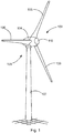
- Figure 1 shows a wind energy installation 100 with a tower 102 and a nacelle 104.
- a rotor 106 with three rotor blades 108 and a spinner 110 is arranged on the nacelle 104.
- the rotor 106 is set in rotation by the wind during operation and thereby drives a generator in the nacelle 104.
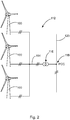
- FIG. 2 shows a wind park 112 with, for example, three wind energy installations 100, which can be the same or different.
- the three wind energy installations 100 are therefore representative of basically any number of wind energy installations in a wind park 112.
- the wind energy installations 100 provide their output, namely in particular the generated electricity, via an electrical park network 114.
- the currents or power generated by the individual wind turbines 100 are added up and a transformer 116 is usually provided, which steps up the voltage in the park in order to then feed it into the supply network 120 at the feed point 118, which is also generally referred to as PCC.
- Fig. 2 is only a simplified representation of a wind farm 112, which shows no control, for example, although a control is of course present.
- the park network 114 can also be designed differently, for example in that a transformer is also present at the output of each wind energy installation 100, to name just one other exemplary embodiment.
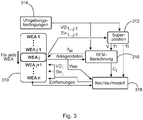
- the diagram of the Figure 3 generally assumes that 1 to n wind turbines are present in a wind farm and would have to be calculated.
- a wind energy installation is abbreviated there as a wind turbine and the index thus ranges from 1 to n.
- the current wind energy installation to be calculated or the associated parameters are identified with the index j.
- the previously calculated wind energy installation is thus identified with the index j-1 and the wind energy installation to be calculated next is correspondingly identified with the index j + 1.
- the wind energy installations are listed symbolically in the parking block 310 and the current wind energy installation is identified as WEA j.
- a wind energy installation can also be referred to synonymously as a wind turbine or wind turbine.
- the method processes the wind energy installations from the first wind energy installation WEA 1 to the last wind energy installation WEA n.
- the result is, among other things, a speed deficit VD and an induced turbulence TI, which act from previous wind energy installations WEA 1 to WEA j-1 on the current wind energy installation WEA j.
- the speed deficits VD 1... J ⁇ 1 and the induced turbulence TI + 1... J ⁇ 1 are thus taken into account and fed to a superposition in the superposition block 312.
- the superposition block 312 receives corresponding environmental conditions from an environmental condition block 314.
- the wind speed can also be viewed as an environmental condition and a shear, i.e.
- a change in the wind speed with the location, in particular with the height, as well as a veer, which indicates a change in the wind direction with the location, in particular with the height, are considered as further environmental conditions , designated.
- the air density can also be an environmental condition.
- the induced turbulence TI can also be referred to as the induced turbulence TI +.
- the total wind speed V acting on the current wind energy installation WEA j and also the overall induced turbulence acting on the current wind energy installation WEA j can then be determined in the superposition block 312. Both variables then form an input variable for a system calculation block 316.
- a leaf element method for calculating the wind energy installation is carried out in the system calculation block 316, namely in particular for calculating the power P el that can be generated.
- the blade element method i.e. the system calculation block 316, also receives the environmental conditions from the environmental condition block 314.
- properties of the wind energy system WEA j itself are also included, namely data such as properties of the wind energy system as such, such as the rotor blades used, as well as current operating settings of the wind turbine concerned.
- the installation calculation block 316 calculates the electrical power P el of the current wind energy installation using the leaf element method.
- the current power P el which can also be referred to or viewed as output power, can be calculated from the aerodynamic variables taking into account the wind park, namely the wind power plants WEA 1 to WEA j-1 potentially located in front of the current wind power plant WEA j.
- This power P el calculated in this way can be returned as information on the current wind energy installation WEA j.
- the relevant wind energy installation WEA j can store this data and make it accessible if necessary.
- a follow-up model 318 is used for this purpose.
- the wake model 318 receives the induced turbulence TI, which acts on the current wind energy installation WEA j, as it was calculated by the superposition block 312.
- the system calculation block 316 also calculates a thrust coefficient C t using the leaf element method, which forms a further input variable for the tracking model 318.
- the azimuth deflection or orientation of the wind turbine is also important for the tracking model. This azimuth orientation can also be referred to as the yaw angle or the yaw angle.
- This azimuth angle thus also forms an input variable for the tracking model 318.
- the position and distance of the respective downstream wind turbines WEA j + 1 to WEA n are also important in relation to the current wind energy installation WEA j, and this also flows into the tracking model as an input variable.
- the speed deficit VD j and the induced turbulence TI j are then calculated on the downstream wind energy installations WEA j + 1 to WEA n.
- the current wind energy installation WEA j also has the speed deficits VD 1 ... ji and induced turbulence TI + i ... j-1 relevant to it through earlier calculations, namely for the wind energy installation WEA 1 to WEA j-1 receive. In this way, all wind energy systems in the wind farm can be calculated.
- FIG. 4 A flow chart 408 is shown which illustrates parking optimization. For the parking optimization, a calculation must be carried out several times, as it is in connection with Figure 3 was explained. For this, the calculation block 410 is shown, which basically corresponds to the in Figure 3 explained process includes. The flow chart of FIG Figure 3 contained in the calculation block 410 as a symbolic miniature.
- the flow diagram 408 particularly illustrates an inner loop 412 and an outer loop 414.
- an optimization sequence is carried out for a plurality of wind turbines, namely one after the other.
- an overall run is completed.
- Such an overall run is repeated with the outer loop 414 in order to improve the result that has already been achieved in a first overall run, or in order to determine that it can no longer be improved or can no longer be improved significantly.
- optimization begins with the first wind energy installation up to the last wind energy installation n.
- the wind energy installations WEA 1 to WEA n to be checked are sorted in a processing sequence that depends on the wind direction.
- Processing block 416 is intended to illustrate this. It is always started with the first wind energy installation, the last one could also be used, and in general the wind energy installation WEA i is then the current wind energy installation which is being optimized.
- an optimization algorithm which is illustrated by the optimization block 418, changes the wind energy installation WEA i currently to be optimized.
- the parameters rotor speed, blade angle and / or azimuth alignment are set or varied as operating settings, namely by the wind energy installation WEA i currently to be optimized.
- the calculation of the wind farm is then carried out in the calculation block 410 with these respectively set parameters, that is to say carried out in the same way as in connection with Figure 3 was explained.
- the result is a total parking result, which is output here as the parking service P park.
- the operating parameters can be further changed in the optimization block 418 until an optimal setting for the parameters has been found for this wind energy installation and thus optimal operating settings have been found for this current wind energy installation WEA i.
- the calculation in the calculation block 410 only needs to be recalculated starting from the wind energy installation i. All upstream wind turbines remain unchanged. This is indicated by the wind energy installation WEAh, which can be shifted accordingly into the overall evaluation block 420, in which the already completely optimized wind energy installations are stored.
- a wind energy installation is optimized in its operating settings, the optimization is carried out for the next wind energy installation, namely in particular for the wind energy installation which is provided next in the processing block 416.
- the list of wind energy installations that have to be calculated in calculation block 410 changes. To this extent, a list on which this is based decreases in number in each iteration step of the inner loop 412. That will be in the Figure 4 illustrated by an old work list 422 being changed to a new work list 424.
- the new processing list 424 is at least one wind energy installation shorter than the old processing list 422.
- the new processing list 424 is reduced by more than just one wind energy installation compared to the old processing list 422.
- the optimization can be repeated according to the inner loop. This is indicated by the outer loop 414. If the multiple pass through the inner loop 412 is repeated, the first pass of the inner loop starts again at the first wind energy installation and all wind energy installations are calculated again as described above.
- This parking performance of the second pass of the outer loop can be compared with the parking performance as a result of the first pass of the outer loop.
- the outer loop 414 can be run through multiple times and the parking power can be recorded each time. Then, on the basis of the recorded parking performance for each run of the outer loop 414, it can be judged whether the optimization was sufficient or should be repeated. If the parking power converges strongly from one to the next iteration of the outer loop 414, the calculation can be completed.
- the result is then an optimal setting of the wind farm at least for one wind direction and one wind speed.
- the wind energy installation h is the installation whose settings have just been successfully optimized. It is therefore put aside, i.e. no longer changed, since its effects are now globally constant for this wind direction, i.e. it is used unchanged for all further calculations of the wind farm with the same optimization wind direction.
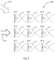
- FIG. 5 illustrates a wind park 500 with nine wind energy installations WT 1 to WT 9.
- the wind park 500 can in principle be the wind park 112 of FIG Figure 2 correspond, which shows three wind turbines only for the sake of illustration.
- the nine wind turbines WT 1 to WT 9 of the Figure 5 are shown illustratively.
- a situation is illustrated in which the wind 510 is basically coming from the left, which is illustrated by a large arrow.
- all wind energy installations WT 1 to WT 9 are aligned with this wind in their azimuth position.
- Each of the wind energy installations WT 1 to WT 9 is symbolically illustrated in a plan view with a nacelle and a rotor with two rotor blades that are horizontally positioned in the illustration. In fact, the rotor with these rotor blades turns naturally and, moreover, modern wind turbines nowadays have three instead of two rotor blades.
- a wind drag S is symbolically drawn in dotted behind each wind energy installation WT 1 to WT 9.
- Such a wake is approximately helical.
- turbulence generally occurs there, namely induced turbulence that was induced by the respective wind energy installation.
- speed deficit which basically indicates that the wind speed is reduced by the wind turbine in front.
- the wind turbines WT 1 to WT 9 can thus also be optimized in this numbered sequence. Then, in the first run of an optimization process, the wind turbine WT 1 would have to be viewed as a forward wind energy installation. All of the following wind energy systems WT 2 to WT 9 can be viewed as trailing wind energy systems for this first optimization process. However, the overrun of the first wind energy installation WT 1 is obviously only relevant for that fourth wind energy installation WT 4. There should also be some effect for the seventh wind energy installation WT 7.
- the operating settings of the wind energy installations WT 1, WT 2 and WT 3 would be set or their optimum would be found.
- the operating settings of the wind energy installations WT 1, WT 2 and WT 3 would remain unchanged, namely to the values that resulted from the first optimization process.
- the wind turbines WT 4, WT 5 and WT 6 can each be viewed as leading wind turbines and the wind turbines WT 7, WT 8 and WT 9 as trailing wind turbines.
- the operating settings of these three forward wind turbines WT 4, WT 5 and WT 6 can then be varied in order to find an optimum.
- the operating settings of the wind turbines WT 7, WT 8 and WT 9 can be adjusted or set, while the operating settings of the other wind turbines WT 1 to WT 6 remain unchanged.
- a consideration of wake wind turbines can be omitted in this last run of the optimization process.
- the wind 510 rotated by 30 °, flows onto the wind farm 500. This is indicated as a second wind 510 'with a dashed arrow.
- a joint consideration of the wind energy installations WT 1, WT 2 and WT 3 at the same time as the first forward wind energy installation is no longer possible or is less possible. It can then be provided to optimize one wind energy installation after the other.
- the wind energy installation WT 1 can be viewed as the first forward wind energy installation and its operating settings can be optimized.
- the other wind turbines can be viewed as trailing wind turbines.
- the greatest effects may arise in the wind direction of the second wind 510 'from the wind energy installation WT 1 on the wind energy installation WT 8.
- the first wind energy installation WT 1 can be regarded as the first leading wind energy installation and the other wind energy installations as wake wind energy installations, which result in the calculation becomes that perhaps only the wind turbine WT 8 is significantly influenced.
- the operating settings of the wind energy installation WT 1 can then remain unchanged, because its operating settings have already been optimized, and the wind energy installation WT 2 can be regarded as the next leading wind energy installation.
- the initial settings of all operating settings of the wind turbines WT 1 to WT 9 being the settings that were found in the first nine runs of the optimization process.
- a general task according to the invention was, in particular, to no longer design the mode of operation of individual wind energy plants as it currently does, so that the individual plant delivers the greatest possible yield, but the entire wind farm delivers an auctioned yield.
- a method is presented to optimize the operating settings such as pitch, speed and yaw angle of wind turbines in wind farms in the course of a cooperative strategy.
- Previously known plant controls use a competitive strategy according to which each wind turbine uses settings that achieve the greatest output for the individual wind turbine instead of the wind farm.
- the actual operating settings can be used as optimization variables. It is possible to make a much more precise forecast of the output achieved by the individual wind turbine as well as the park. In addition, the effect of increased turbulence intensity on the wind turbines can be checked.
- the flow conditions for each wind turbine must first be determined.
- the flow can be impaired by a wake. This applies to upstream wind turbines that are in the wake of another wind turbine.
- This impairment which becomes noticeable through a reduction in wind speed and an increase in turbulence intensity, can be determined using analytical tracking models such as the NO-Jensen or the Qian model.
- the preferred method presented here uses the Qian model, which has the advantage of also taking into account the deflection of the caster due to an intentional incorrect setting of the yaw angle.
- the other models can also be considered.
- the increased turbulence intensity in the wake can be determined.
- a list of wind turbine objects is created, that is to say a list of wind energy installations in the wind park.
- the speed, the blade pitch and yaw angle are available as optimization variables.
- the number of variables is therefore equal to three times the number of wind turbines in the park. These must also be varied with the wind speed and the wind direction.
- the optimization is carried out successively for the wind turbines 1 to n as follows, the current wind turbine being referred to as wind turbine i in each case.
- wind turbine i the current wind turbine
- the total parking performance is used as the target variable, i.e. the variable to be optimized.
- the operating settings of the wind turbines downstream of 'i' are considered to be constant.
- the wind farm only needs to be recalculated from the wind turbine 'i', all the upstream wind turbines remain unchanged. Your input and output parameters are therefore also constant.
- the operating parameters can be changed so slowly that a reaction of the overall parking result can be assigned to the respective change in the operating parameters.
- the wind turbine to be optimized 'i' is iterated from the first to the last wind turbine: There is therefore a run from the first to the last wind turbine and the currently optimized wind turbine is referred to as wind turbine, i '.
- wind turbine i '.
- the upstream wind turbines are optimized based on the settings of the downstream wind turbines, which can change later. Therefore, after the optimization of the last wind turbine, the list is replenished and started again from the first one. This is repeated until the parking performance converges, which usually happens after a few parking passes.
- the proposed idea proposes establishments that already take into account lag effects in the creation process and can thus increase the parking yield.
Landscapes
- Engineering & Computer Science (AREA)
- Business, Economics & Management (AREA)
- Sustainable Development (AREA)
- Sustainable Energy (AREA)
- Chemical & Material Sciences (AREA)
- Combustion & Propulsion (AREA)
- Mechanical Engineering (AREA)
- General Engineering & Computer Science (AREA)
- Life Sciences & Earth Sciences (AREA)
- Economics (AREA)
- Human Resources & Organizations (AREA)
- Strategic Management (AREA)
- Physics & Mathematics (AREA)
- Tourism & Hospitality (AREA)
- Theoretical Computer Science (AREA)
- General Physics & Mathematics (AREA)
- Entrepreneurship & Innovation (AREA)
- General Business, Economics & Management (AREA)
- Marketing (AREA)
- Health & Medical Sciences (AREA)
- Quality & Reliability (AREA)
- Operations Research (AREA)
- Game Theory and Decision Science (AREA)
- Development Economics (AREA)
- Fluid Mechanics (AREA)
- Educational Administration (AREA)
- Public Health (AREA)
- Water Supply & Treatment (AREA)
- General Health & Medical Sciences (AREA)
- Primary Health Care (AREA)
- Wind Motors (AREA)
Applications Claiming Priority (1)
| Application Number | Priority Date | Filing Date | Title |
|---|---|---|---|
| DE102019135582 | 2019-12-20 |
Publications (3)
| Publication Number | Publication Date |
|---|---|
| EP3839251A1 true EP3839251A1 (fr) | 2021-06-23 |
| EP3839251C0 EP3839251C0 (fr) | 2025-09-03 |
| EP3839251B1 EP3839251B1 (fr) | 2025-09-03 |
Family
ID=73789823
Family Applications (1)
| Application Number | Title | Priority Date | Filing Date |
|---|---|---|---|
| EP20212592.8A Active EP3839251B1 (fr) | 2019-12-20 | 2020-12-08 | Optimisation d'un parc éolien |
Country Status (3)
| Country | Link |
|---|---|
| US (1) | US12055128B2 (fr) |
| EP (1) | EP3839251B1 (fr) |
| CN (1) | CN113011994A (fr) |
Cited By (1)
| Publication number | Priority date | Publication date | Assignee | Title |
|---|---|---|---|---|
| CN116412069A (zh) * | 2021-12-31 | 2023-07-11 | 北京金风科创风电设备有限公司 | 风力发电机组的尾流控制方法及相关装置 |
Families Citing this family (5)
| Publication number | Priority date | Publication date | Assignee | Title |
|---|---|---|---|---|
| NL2024238B1 (en) * | 2019-11-14 | 2021-07-29 | Univ Delft Tech | Enhanced wind turbine wake mixing |
| WO2021121510A1 (fr) * | 2019-12-17 | 2021-06-24 | Vestas Wind Systems A/S | Blocage de parc éolien |
| CN113836836B (zh) * | 2021-09-03 | 2024-05-31 | 华北电力大学 | 风电场的推力分配协同控制优化方法 |
| CN119150721B (zh) * | 2024-07-19 | 2025-10-10 | 湖南大学 | 基于风电场实测风速的工程尾流模型动态修正方法及系统 |
| CN119508136B (zh) * | 2024-11-25 | 2025-06-20 | 华电新能源集团股份有限公司福清分公司 | 基于最大流分析的风电机组控制优化方法与系统 |
Citations (4)
| Publication number | Priority date | Publication date | Assignee | Title |
|---|---|---|---|---|
| EP2940296A1 (fr) * | 2014-04-29 | 2015-11-04 | General Electric Company | Systèmes et procédés pour optimiser le fonctionnement d'un parc éolien |
| DE102017105165A1 (de) * | 2017-03-10 | 2018-09-13 | Wobben Properties Gmbh | Verfahren zum Bestimmen einer verfügbaren Leistung eines Windparks und zugehöriger Windpark |
| EP3376026A1 (fr) * | 2017-03-13 | 2018-09-19 | Nordex Energy GmbH | Procédé de réglage de la puissance active d'un parc éolien et parc éolien correspondant |
| EP3536948A1 (fr) * | 2018-03-08 | 2019-09-11 | Siemens Gamesa Renewable Energy A/S | Détermination des réglages de commande pour éolienne |
Family Cites Families (6)
| Publication number | Priority date | Publication date | Assignee | Title |
|---|---|---|---|---|
| US9201410B2 (en) * | 2011-12-23 | 2015-12-01 | General Electric Company | Methods and systems for optimizing farm-level metrics in a wind farm |
| EP3037657A1 (fr) * | 2014-12-23 | 2016-06-29 | ABB Technology AG | Fonctionnement optimal de parc éolien |
| US10260481B2 (en) * | 2016-06-28 | 2019-04-16 | General Electric Company | System and method for assessing farm-level performance of a wind farm |
| CN106203695B (zh) | 2016-07-07 | 2020-01-14 | 华北电力大学 | 一种降低尾流效应的风电场内优化调度方法 |
| ES2774695T3 (es) | 2017-07-10 | 2020-07-22 | Nordex Energy Gmbh | Procedimiento para la regulación de la emisión de potencia efectiva de un parque eólico así como un parque eólico correspondiente |
| DE102017009837A1 (de) * | 2017-10-23 | 2019-04-25 | Senvion Gmbh | Steuerungssystem und Verfahren zum Betreiben einer Mehrzahl von Windenergieanlagen |
-
2020
- 2020-12-08 EP EP20212592.8A patent/EP3839251B1/fr active Active
- 2020-12-15 US US17/122,547 patent/US12055128B2/en active Active
- 2020-12-21 CN CN202011520500.XA patent/CN113011994A/zh not_active Withdrawn
Patent Citations (4)
| Publication number | Priority date | Publication date | Assignee | Title |
|---|---|---|---|---|
| EP2940296A1 (fr) * | 2014-04-29 | 2015-11-04 | General Electric Company | Systèmes et procédés pour optimiser le fonctionnement d'un parc éolien |
| DE102017105165A1 (de) * | 2017-03-10 | 2018-09-13 | Wobben Properties Gmbh | Verfahren zum Bestimmen einer verfügbaren Leistung eines Windparks und zugehöriger Windpark |
| EP3376026A1 (fr) * | 2017-03-13 | 2018-09-19 | Nordex Energy GmbH | Procédé de réglage de la puissance active d'un parc éolien et parc éolien correspondant |
| EP3536948A1 (fr) * | 2018-03-08 | 2019-09-11 | Siemens Gamesa Renewable Energy A/S | Détermination des réglages de commande pour éolienne |
Non-Patent Citations (1)
| Title |
|---|
| HEER FLAVIO ET AL: "Model based power optimisation of wind farms", 2014 EUROPEAN CONTROL CONFERENCE (ECC), EUCA, 24 June 2014 (2014-06-24), pages 1145 - 1150, XP032623546, ISBN: 978-3-9524269-1-3, [retrieved on 20140722], DOI: 10.1109/ECC.2014.6862365 * |
Cited By (1)
| Publication number | Priority date | Publication date | Assignee | Title |
|---|---|---|---|---|
| CN116412069A (zh) * | 2021-12-31 | 2023-07-11 | 北京金风科创风电设备有限公司 | 风力发电机组的尾流控制方法及相关装置 |
Also Published As
| Publication number | Publication date |
|---|---|
| US12055128B2 (en) | 2024-08-06 |
| EP3839251C0 (fr) | 2025-09-03 |
| US20210190040A1 (en) | 2021-06-24 |
| CN113011994A (zh) | 2021-06-22 |
| EP3839251B1 (fr) | 2025-09-03 |
Similar Documents
| Publication | Publication Date | Title |
|---|---|---|
| EP3839251B1 (fr) | Optimisation d'un parc éolien | |
| EP2145103B1 (fr) | Procédé permettant de faire fonctionner une centrale éolienne comprenant une pluralité d'éoliennes | |
| EP1817496B1 (fr) | Procede pour optimaliser le fonctionnement d'installations d'energie eolienne | |
| EP2994970B1 (fr) | Procédé d'injection de puissance électrique dans un réseau de distribution électrique | |
| EP2994971B1 (fr) | Procédé d'injection d'une puissance électrique dans un réseau de distribution électrique | |
| EP3527816B1 (fr) | Procédé et système de détermination d'une fonction de correction d'alignement | |
| AT517774B1 (de) | Windenergieanlage und Windpark mit Windenergieanlage | |
| EP3926162B1 (fr) | Procédé de fonctionnement d'une éolienne, dispositif de commande destiné au fonctionnement d'un éolienne et parc éolien | |
| EP4407827A2 (fr) | Procédé de commande d'un réseau de distribution électrique | |
| EP4227523B1 (fr) | Procédé de fonctionnement d'un parc éolien, éolienne et parc éolien | |
| DE112018001318T5 (de) | Windleistungserzeugungssystem | |
| EP2745007B2 (fr) | Détermination de la perte de rendement énergétique d'une éolienne | |
| EP3832128A1 (fr) | Procédé de commande d'une ferme éolienne | |
| EP3669454B1 (fr) | Procédé et dispositif de détection d'une puissance maximale d'une installation photovoltaïque | |
| EP3772584A1 (fr) | Commande d'un parc éolien | |
| WO2012007111A2 (fr) | Procédé et dispositif pour produire un signal de correction d'angle d'attaque pour une pale de rotor prédéterminée d'une éolienne | |
| DE102018113706A1 (de) | Verfahren zum Betreiben einer Windenergieanlage, Windenergieanlage und Windpark | |
| EP4084261A1 (fr) | Procédé d'injection de l'énergie électrique dans un réseau d'alimentation électrique | |
| EP3891384B1 (fr) | Procédé servant à faire fonctionner au moins une éolienne, ainsi que dispositif associé | |
| EP3587805B1 (fr) | Système de détermination de la performance disponible d'un parc éolien | |
| DE102015009959A1 (de) | Steuerung und Steuerungsverfahren für eine Windenergieanlage oder eine Mehrzahl von Windenergieanlagen | |
| EP3995690B1 (fr) | Procédé de conception d'un parc éolien | |
| EP3499023A1 (fr) | Procédé et système de fonctionnement d'une éolienne | |
| EP3425197A1 (fr) | Réduction de la puissance d'une pluralité d'éoliennes dans un parc éolien | |
| EP4020742A1 (fr) | Procédé de détermination d'une puissance de perte |
Legal Events
| Date | Code | Title | Description |
|---|---|---|---|
| PUAI | Public reference made under article 153(3) epc to a published international application that has entered the european phase |
Free format text: ORIGINAL CODE: 0009012 |
|
| STAA | Information on the status of an ep patent application or granted ep patent |
Free format text: STATUS: THE APPLICATION HAS BEEN PUBLISHED |
|
| AK | Designated contracting states |
Kind code of ref document: A1 Designated state(s): AL AT BE BG CH CY CZ DE DK EE ES FI FR GB GR HR HU IE IS IT LI LT LU LV MC MK MT NL NO PL PT RO RS SE SI SK SM TR |
|
| STAA | Information on the status of an ep patent application or granted ep patent |
Free format text: STATUS: REQUEST FOR EXAMINATION WAS MADE |
|
| 17P | Request for examination filed |
Effective date: 20211223 |
|
| RBV | Designated contracting states (corrected) |
Designated state(s): AL AT BE BG CH CY CZ DE DK EE ES FI FR GB GR HR HU IE IS IT LI LT LU LV MC MK MT NL NO PL PT RO RS SE SI SK SM TR |
|
| STAA | Information on the status of an ep patent application or granted ep patent |
Free format text: STATUS: EXAMINATION IS IN PROGRESS |
|
| 17Q | First examination report despatched |
Effective date: 20230208 |
|
| GRAP | Despatch of communication of intention to grant a patent |
Free format text: ORIGINAL CODE: EPIDOSNIGR1 |
|
| STAA | Information on the status of an ep patent application or granted ep patent |
Free format text: STATUS: GRANT OF PATENT IS INTENDED |
|
| INTG | Intention to grant announced |
Effective date: 20250423 |
|
| GRAS | Grant fee paid |
Free format text: ORIGINAL CODE: EPIDOSNIGR3 |
|
| GRAA | (expected) grant |
Free format text: ORIGINAL CODE: 0009210 |
|
| STAA | Information on the status of an ep patent application or granted ep patent |
Free format text: STATUS: THE PATENT HAS BEEN GRANTED |
|
| AK | Designated contracting states |
Kind code of ref document: B1 Designated state(s): AL AT BE BG CH CY CZ DE DK EE ES FI FR GB GR HR HU IE IS IT LI LT LU LV MC MK MT NL NO PL PT RO RS SE SI SK SM TR |
|
| REG | Reference to a national code |
Ref country code: CH Ref legal event code: EP |
|
| REG | Reference to a national code |
Ref country code: IE Ref legal event code: FG4D Free format text: LANGUAGE OF EP DOCUMENT: GERMAN |
|
| U01 | Request for unitary effect filed |
Effective date: 20250903 |
|
| U07 | Unitary effect registered |
Designated state(s): AT BE BG DE DK EE FI FR IT LT LU LV MT NL PT RO SE SI Effective date: 20250909 |
|
| U20 | Renewal fee for the european patent with unitary effect paid |
Year of fee payment: 6 Effective date: 20251128 |
|
| PGFP | Annual fee paid to national office [announced via postgrant information from national office to epo] |
Ref country code: GB Payment date: 20251218 Year of fee payment: 6 |
|
| PG25 | Lapsed in a contracting state [announced via postgrant information from national office to epo] |
Ref country code: NO Free format text: LAPSE BECAUSE OF FAILURE TO SUBMIT A TRANSLATION OF THE DESCRIPTION OR TO PAY THE FEE WITHIN THE PRESCRIBED TIME-LIMIT Effective date: 20251203 |
|
| PG25 | Lapsed in a contracting state [announced via postgrant information from national office to epo] |
Ref country code: HR Free format text: LAPSE BECAUSE OF FAILURE TO SUBMIT A TRANSLATION OF THE DESCRIPTION OR TO PAY THE FEE WITHIN THE PRESCRIBED TIME-LIMIT Effective date: 20250903 |
|
| PG25 | Lapsed in a contracting state [announced via postgrant information from national office to epo] |
Ref country code: GR Free format text: LAPSE BECAUSE OF FAILURE TO SUBMIT A TRANSLATION OF THE DESCRIPTION OR TO PAY THE FEE WITHIN THE PRESCRIBED TIME-LIMIT Effective date: 20251204 |
|
| PG25 | Lapsed in a contracting state [announced via postgrant information from national office to epo] |
Ref country code: PL Free format text: LAPSE BECAUSE OF FAILURE TO SUBMIT A TRANSLATION OF THE DESCRIPTION OR TO PAY THE FEE WITHIN THE PRESCRIBED TIME-LIMIT Effective date: 20250903 |
|
| PG25 | Lapsed in a contracting state [announced via postgrant information from national office to epo] |
Ref country code: RS Free format text: LAPSE BECAUSE OF FAILURE TO SUBMIT A TRANSLATION OF THE DESCRIPTION OR TO PAY THE FEE WITHIN THE PRESCRIBED TIME-LIMIT Effective date: 20251203 |
|
| PG25 | Lapsed in a contracting state [announced via postgrant information from national office to epo] |
Ref country code: ES Free format text: LAPSE BECAUSE OF FAILURE TO SUBMIT A TRANSLATION OF THE DESCRIPTION OR TO PAY THE FEE WITHIN THE PRESCRIBED TIME-LIMIT Effective date: 20250903 |
|
| PG25 | Lapsed in a contracting state [announced via postgrant information from national office to epo] |
Ref country code: SM Free format text: LAPSE BECAUSE OF FAILURE TO SUBMIT A TRANSLATION OF THE DESCRIPTION OR TO PAY THE FEE WITHIN THE PRESCRIBED TIME-LIMIT Effective date: 20250903 |
|
| PG25 | Lapsed in a contracting state [announced via postgrant information from national office to epo] |
Ref country code: IS Free format text: LAPSE BECAUSE OF FAILURE TO SUBMIT A TRANSLATION OF THE DESCRIPTION OR TO PAY THE FEE WITHIN THE PRESCRIBED TIME-LIMIT Effective date: 20260103 |
|
| PG25 | Lapsed in a contracting state [announced via postgrant information from national office to epo] |
Ref country code: CZ Free format text: LAPSE BECAUSE OF FAILURE TO SUBMIT A TRANSLATION OF THE DESCRIPTION OR TO PAY THE FEE WITHIN THE PRESCRIBED TIME-LIMIT Effective date: 20250903 |
|
| PG25 | Lapsed in a contracting state [announced via postgrant information from national office to epo] |
Ref country code: SK Free format text: LAPSE BECAUSE OF FAILURE TO SUBMIT A TRANSLATION OF THE DESCRIPTION OR TO PAY THE FEE WITHIN THE PRESCRIBED TIME-LIMIT Effective date: 20250903 |