EP4020742A1 - Procédé de détermination d'une puissance de perte - Google Patents
Procédé de détermination d'une puissance de perte Download PDFInfo
- Publication number
- EP4020742A1 EP4020742A1 EP20217430.6A EP20217430A EP4020742A1 EP 4020742 A1 EP4020742 A1 EP 4020742A1 EP 20217430 A EP20217430 A EP 20217430A EP 4020742 A1 EP4020742 A1 EP 4020742A1
- Authority
- EP
- European Patent Office
- Prior art keywords
- wind farm
- wind
- power
- determining
- power loss
- Prior art date
- Legal status (The legal status is an assumption and is not a legal conclusion. Google has not performed a legal analysis and makes no representation as to the accuracy of the status listed.)
- Pending
Links
Images


Classifications
-
- H—ELECTRICITY
- H02—GENERATION; CONVERSION OR DISTRIBUTION OF ELECTRIC POWER
- H02J—ELECTRIC POWER NETWORKS; CIRCUIT ARRANGEMENTS OR SYSTEMS FOR SUPPLYING OR DISTRIBUTING ELECTRIC POWER; SYSTEMS FOR STORING ELECTRIC ENERGY
- H02J3/00—Circuit arrangements for AC mains or AC distribution networks
- H02J3/38—Arrangements for feeding a single network from two or more generators or sources in parallel; Arrangements for feeding already energised networks from additional generators or sources in parallel
- H02J3/381—Dispersed generators
-
- F—MECHANICAL ENGINEERING; LIGHTING; HEATING; WEAPONS; BLASTING
- F03—MACHINES OR ENGINES FOR LIQUIDS; WIND, SPRING, OR WEIGHT MOTORS; PRODUCING MECHANICAL POWER OR A REACTIVE PROPULSIVE THRUST, NOT OTHERWISE PROVIDED FOR
- F03D—WIND MOTORS
- F03D7/00—Controlling wind motors
- F03D7/02—Controlling wind motors the wind motors having rotation axis substantially parallel to the air flow entering the rotor
- F03D7/028—Controlling wind motors the wind motors having rotation axis substantially parallel to the air flow entering the rotor controlling wind motor output power
- F03D7/0284—Controlling wind motors the wind motors having rotation axis substantially parallel to the air flow entering the rotor controlling wind motor output power in relation to the state of the electric grid
-
- F—MECHANICAL ENGINEERING; LIGHTING; HEATING; WEAPONS; BLASTING
- F03—MACHINES OR ENGINES FOR LIQUIDS; WIND, SPRING, OR WEIGHT MOTORS; PRODUCING MECHANICAL POWER OR A REACTIVE PROPULSIVE THRUST, NOT OTHERWISE PROVIDED FOR
- F03D—WIND MOTORS
- F03D7/00—Controlling wind motors
- F03D7/02—Controlling wind motors the wind motors having rotation axis substantially parallel to the air flow entering the rotor
- F03D7/04—Automatic control; Regulation
- F03D7/042—Automatic control; Regulation by means of an electrical or electronic controller
- F03D7/048—Automatic control; Regulation by means of an electrical or electronic controller controlling wind farms
-
- H—ELECTRICITY
- H02—GENERATION; CONVERSION OR DISTRIBUTION OF ELECTRIC POWER
- H02J—ELECTRIC POWER NETWORKS; CIRCUIT ARRANGEMENTS OR SYSTEMS FOR SUPPLYING OR DISTRIBUTING ELECTRIC POWER; SYSTEMS FOR STORING ELECTRIC ENERGY
- H02J13/00—Circuit arrangements for providing remote monitoring or remote control of equipment in a power distribution network
- H02J13/12—Monitoring network conditions, e.g. electrical magnitudes or operational status
-
- F—MECHANICAL ENGINEERING; LIGHTING; HEATING; WEAPONS; BLASTING
- F05—INDEXING SCHEMES RELATING TO ENGINES OR PUMPS IN VARIOUS SUBCLASSES OF CLASSES F01-F04
- F05B—INDEXING SCHEME RELATING TO WIND, SPRING, WEIGHT, INERTIA OR LIKE MOTORS, TO MACHINES OR ENGINES FOR LIQUIDS COVERED BY SUBCLASSES F03B, F03D AND F03G
- F05B2260/00—Function
- F05B2260/82—Forecasts
- F05B2260/821—Parameter estimation or prediction
-
- F—MECHANICAL ENGINEERING; LIGHTING; HEATING; WEAPONS; BLASTING
- F05—INDEXING SCHEMES RELATING TO ENGINES OR PUMPS IN VARIOUS SUBCLASSES OF CLASSES F01-F04
- F05B—INDEXING SCHEME RELATING TO WIND, SPRING, WEIGHT, INERTIA OR LIKE MOTORS, TO MACHINES OR ENGINES FOR LIQUIDS COVERED BY SUBCLASSES F03B, F03D AND F03G
- F05B2270/00—Control
- F05B2270/10—Purpose of the control system
- F05B2270/103—Purpose of the control system to affect the output of the engine
- F05B2270/1033—Power (if explicitly mentioned)
-
- F—MECHANICAL ENGINEERING; LIGHTING; HEATING; WEAPONS; BLASTING
- F05—INDEXING SCHEMES RELATING TO ENGINES OR PUMPS IN VARIOUS SUBCLASSES OF CLASSES F01-F04
- F05B—INDEXING SCHEME RELATING TO WIND, SPRING, WEIGHT, INERTIA OR LIKE MOTORS, TO MACHINES OR ENGINES FOR LIQUIDS COVERED BY SUBCLASSES F03B, F03D AND F03G
- F05B2270/00—Control
- F05B2270/30—Control parameters, e.g. input parameters
- F05B2270/335—Output power or torque
-
- G—PHYSICS
- G01—MEASURING; TESTING
- G01R—MEASURING ELECTRIC VARIABLES; MEASURING MAGNETIC VARIABLES
- G01R21/00—Arrangements for measuring electric power or power factor
-
- H—ELECTRICITY
- H02—GENERATION; CONVERSION OR DISTRIBUTION OF ELECTRIC POWER
- H02J—ELECTRIC POWER NETWORKS; CIRCUIT ARRANGEMENTS OR SYSTEMS FOR SUPPLYING OR DISTRIBUTING ELECTRIC POWER; SYSTEMS FOR STORING ELECTRIC ENERGY
- H02J2101/00—Supply or distribution of decentralised, dispersed or local electric power generation
- H02J2101/20—Dispersed power generation using renewable energy sources
- H02J2101/28—Wind energy
-
- H—ELECTRICITY
- H02—GENERATION; CONVERSION OR DISTRIBUTION OF ELECTRIC POWER
- H02J—ELECTRIC POWER NETWORKS; CIRCUIT ARRANGEMENTS OR SYSTEMS FOR SUPPLYING OR DISTRIBUTING ELECTRIC POWER; SYSTEMS FOR STORING ELECTRIC ENERGY
- H02J2105/00—Networks for supplying or distributing electric power characterised by their spatial reach or by the load
- H02J2105/10—Local stationary networks having a local or delimited stationary reach
- H02J2105/16—Local stationary networks having a local or delimited stationary reach being internal to power sources or power generation plants
-
- H—ELECTRICITY
- H02—GENERATION; CONVERSION OR DISTRIBUTION OF ELECTRIC POWER
- H02J—ELECTRIC POWER NETWORKS; CIRCUIT ARRANGEMENTS OR SYSTEMS FOR SUPPLYING OR DISTRIBUTING ELECTRIC POWER; SYSTEMS FOR STORING ELECTRIC ENERGY
- H02J3/00—Circuit arrangements for AC mains or AC distribution networks
- H02J3/38—Arrangements for feeding a single network from two or more generators or sources in parallel; Arrangements for feeding already energised networks from additional generators or sources in parallel
- H02J3/46—Controlling the sharing of generated power between the generators, sources or networks
-
- Y—GENERAL TAGGING OF NEW TECHNOLOGICAL DEVELOPMENTS; GENERAL TAGGING OF CROSS-SECTIONAL TECHNOLOGIES SPANNING OVER SEVERAL SECTIONS OF THE IPC; TECHNICAL SUBJECTS COVERED BY FORMER USPC CROSS-REFERENCE ART COLLECTIONS [XRACs] AND DIGESTS
- Y02—TECHNOLOGIES OR APPLICATIONS FOR MITIGATION OR ADAPTATION AGAINST CLIMATE CHANGE
- Y02E—REDUCTION OF GREENHOUSE GAS [GHG] EMISSIONS, RELATED TO ENERGY GENERATION, TRANSMISSION OR DISTRIBUTION
- Y02E10/00—Energy generation through renewable energy sources
- Y02E10/70—Wind energy
- Y02E10/72—Wind turbines with rotation axis in wind direction
-
- Y—GENERAL TAGGING OF NEW TECHNOLOGICAL DEVELOPMENTS; GENERAL TAGGING OF CROSS-SECTIONAL TECHNOLOGIES SPANNING OVER SEVERAL SECTIONS OF THE IPC; TECHNICAL SUBJECTS COVERED BY FORMER USPC CROSS-REFERENCE ART COLLECTIONS [XRACs] AND DIGESTS
- Y02—TECHNOLOGIES OR APPLICATIONS FOR MITIGATION OR ADAPTATION AGAINST CLIMATE CHANGE
- Y02E—REDUCTION OF GREENHOUSE GAS [GHG] EMISSIONS, RELATED TO ENERGY GENERATION, TRANSMISSION OR DISTRIBUTION
- Y02E10/00—Energy generation through renewable energy sources
- Y02E10/70—Wind energy
- Y02E10/76—Power conversion electric or electronic aspects
-
- Y—GENERAL TAGGING OF NEW TECHNOLOGICAL DEVELOPMENTS; GENERAL TAGGING OF CROSS-SECTIONAL TECHNOLOGIES SPANNING OVER SEVERAL SECTIONS OF THE IPC; TECHNICAL SUBJECTS COVERED BY FORMER USPC CROSS-REFERENCE ART COLLECTIONS [XRACs] AND DIGESTS
- Y02—TECHNOLOGIES OR APPLICATIONS FOR MITIGATION OR ADAPTATION AGAINST CLIMATE CHANGE
- Y02E—REDUCTION OF GREENHOUSE GAS [GHG] EMISSIONS, RELATED TO ENERGY GENERATION, TRANSMISSION OR DISTRIBUTION
- Y02E40/00—Technologies for an efficient electrical power generation, transmission or distribution
- Y02E40/70—Smart grids as climate change mitigation technology in the energy generation sector
-
- Y—GENERAL TAGGING OF NEW TECHNOLOGICAL DEVELOPMENTS; GENERAL TAGGING OF CROSS-SECTIONAL TECHNOLOGIES SPANNING OVER SEVERAL SECTIONS OF THE IPC; TECHNICAL SUBJECTS COVERED BY FORMER USPC CROSS-REFERENCE ART COLLECTIONS [XRACs] AND DIGESTS
- Y04—INFORMATION OR COMMUNICATION TECHNOLOGIES HAVING AN IMPACT ON OTHER TECHNOLOGY AREAS
- Y04S—SYSTEMS INTEGRATING TECHNOLOGIES RELATED TO POWER NETWORK OPERATION, COMMUNICATION OR INFORMATION TECHNOLOGIES FOR IMPROVING THE ELECTRICAL POWER GENERATION, TRANSMISSION, DISTRIBUTION, MANAGEMENT OR USAGE, i.e. SMART GRIDS
- Y04S10/00—Systems supporting electrical power generation, transmission or distribution
- Y04S10/12—Monitoring or controlling equipment for energy generation units, e.g. distributed energy generation [DER] or load-side generation
- Y04S10/123—Monitoring or controlling equipment for energy generation units, e.g. distributed energy generation [DER] or load-side generation the energy generation units being or involving renewable energy sources
Definitions
- the present invention relates to a method for determining a power loss of a wind farm and a wind farm controlled therewith.
- Wind farms usually have a large number of wind energy installations which are connected to one another via a common wind farm network and are controlled via a large number of signals, for example by means of a wind farm control unit.
- One of these signals is the so-called available power, which indicates how much power a wind farm or an individual wind turbine can produce, taking into account the prevailing wind.
- wind farms can be operated in a particularly yield-optimized manner, for example for the provision of balancing power and/or for direct marketing.
- a disadvantage of previously known methods for determining an available power of a wind farm is that the calculation is carried out exclusively using a prevailing wind and can therefore be extremely inaccurate.
- the object of the present invention is therefore to provide an improved signal for the available power of a wind farm, in particular this signal should also take into account any losses from a wind farm.
- a method for determining a power loss of a wind farm connected to a grid connection point of an electrical supply grid is proposed, the wind farm having a large number of wind turbines which are connected together via an electrical wind farm grid and each have a converter for feeding electrical power into the electrical wind farm grid .
- a current to be fed in by the wind farm is determined, in particular at the grid connection point of the wind farm. This can be done, for example, by measuring directly at the grid connection point and/or by calculation.
- the resistance of the wind farm is determined.
- the resistance for the wind farm that generates the electricity to be fed in and feeds it in at the grid connection point is therefore determined.
- the resistance usually results from the topology of the wind farm and indicates the total electrical resistance for the wind farm from the grid connection point, e.g. to the converter terminals of the wind turbines.
- the resistance of the wind farm is preferably an impedance.
- the power loss of the wind farm is determined, taking into account the current to be fed in and the wind farm resistance.
- the additional converter losses of the wind energy installations can also be taken into account when determining the power loss of the wind farm.
- the simplified equivalent circuit diagram depicts the wind farm network.
- the wind farm charging power or the wind farm capacity is taken into account when determining the power loss of the wind farm.
- a charging power is understood to mean in particular that reactive power which an electrical component absorbs.
- the wind farm charging power therefore describes in particular the power that the wind farm network consumes, in particular when zero active power is fed in.
- the method thus makes it possible, in particular, to determine the power loss of a wind farm with a one-off calculation, ie in particular not to use an iterative method, as is the case with a complicated load flow calculation.
- the method for determining the power loss can be linearized and thus greatly simplified and thus executed on every wind farm control unit.
- the method described above and/or below is therefore particularly suitable for being executed on a particularly conventional wind farm control unit.
- the method also includes the step: determining an available power of the wind farm, in particular taking into account a prevailing one Wind and the electricity to be fed in is determined depending on the available power of the wind farm.
- the available power of the wind power plant can then be calculated, for example using structural parameters of the wind power plant, for example using the prevailing wind, the wind class of the wind farm or the wind power plants of the wind farm and the nominal power of the wind farm or the wind power plants , then the available power of the wind farm can be determined.
- the available power of the wind energy installation or of the wind farm can also be derived from operating data of the wind energy installation, for example using a wind estimator and a rotor-effective wind speed.
- the current to be fed in and thus the power loss are thus determined as a function of the available power of the wind farm, which was preferably determined on the basis of a prevailing wind.
- the method also includes the step: determining a voltage at the grid connection point; and wherein the current to be fed in is determined as a function of the voltage at the grid connection point.
- the voltage at the grid connection point can, for example, be measured directly at the grid connection point, or requested from the grid operator and/or specified as a target value.
- the wind farm resistance preferably describes the wind farm from the grid connection point.
- the power loss of the wind farm is preferably determined using a simplified equivalent circuit diagram, in particular a single-phase equivalent circuit diagram.
- the additional converter losses of the wind turbines can also be taken into account when calculating the power loss of the wind farm.
- the power loss of the wind farm is preferably determined taking into account a reactive power operating point of the wind farm.
- the reactive power operating point is preferably the operating point of the wind farm at a maximum potential active power of the wind farm.
- the reactive power operating point is, for example, estimated or calculated, in particular depending on the mode of operation of the wind farm, for example a cos( ⁇ ) control or a Q(U) control.
- the reactive power operating point is preferably read from a look-up table.
- a reactive power requirement of the electrical wind farm network is preferably also determined and taken into account in the calculation of the power loss.
- the power loss of the wind farm is preferably determined taking into account a voltage sensitivity, in particular at the grid connection point.
- the electricity to be fed in from the wind farm at the grid connection point is calculated.
- This current to be fed in can, for example, lead to a voltage change at the grid connection point, which must also be taken into account.
- the power loss of the wind farm for a reactive charging power is preferably determined at zero active power.
- the power loss of the wind farm is preferably also determined taking into account the additional converter losses of the wind turbines.
- the additional converter losses are to be understood in particular as the additional converter losses caused by reactive power.
- the reactive power requirement of the farm network varies, for example, depending on the active power operating point between a capacitive reactive power reference at zero active power of e.g. approx. 5% capacitive (related to the amount of the maximum active power) and 15% inductive at maximum active power. If, for example, the reactive power at the grid connection point is to be zero, the wind turbines must produce between 5% inductive and 15% capacitive reactive power, depending on the operating point.
- These additional converter losses are preferably converter losses caused by reactive power.
- the additional converter losses can be determined, for example, from a look-up table or by calculation.
- the additional converter losses are preferably determined by calculation, for example by means of an equation, in particular a linearized one.
- the power loss of the wind farm is then determined from the values determined in this way.
- the wind park resistance or a park factor can also be used for this, for example.
- a method for determining an available power of a wind farm having a plurality of wind energy installations comprising the steps: determining an available power of the wind energy installations taking into account a prevailing wind; Calculating the available power of the wind farm using the available active power of the wind turbines and a power loss of the wind farm, which was determined using a method described above or below.
- the available capacity of the wind farm determined in this way is many times more precise than previously known methods and can, for example, be transmitted to a grid operator for the provision of balancing power and/or for direct marketing.
- wind farms can be operated in a more yield-optimized manner, in particular since the operating points of a wind farm can be described more precisely with the methods described above or below.
- the available power of the wind farm is preferably also calculated taking into account an available active power of the wind energy installations.
- a method for controlling a wind farm comprising the steps: controlling the wind farm taking into account an available power of the wind farm, which was determined using a method described above or below.
- a wind farm which comprises a multiplicity of wind energy installations and a wind farm control unit, the wind farm control unit being set up to carry out at least one of the methods described above or below.
- the wind farm thus has, for example, a large number of wind energy installations which are connected to one another via a common wind farm network.
- These wind energy installations preferably each have a converter, by means of which the wind energy installations feed electrical power into the electrical wind farm network.
- the wind energy installations also have at least one wind energy installation control unit, by means of which the wind energy installation is controlled.
- the wind farm is preferably connected to the electrical supply network via a transformer, in particular at the network connection point.
- the wind farm also has a wind farm control unit that is set up to control the wind turbines via the wind turbine control units.
- the wind farm control unit preferably also has at least one look-up table.
- the look-up table can be used, for example, to determine a reactive power operating point of the wind farm, a voltage of the wind farm at the grid connection point and/or the additional converter losses.
- the look-up table is, for example, structured in such a way that a relative working point of the active power (preferably in 1% increments) and a relative working point of the reactive power (preferably in 1% increments) can be read, in particular in order to determine the additional to determine relative losses due to the reactive power operating point.
- the look-up table can be determined, for example, using measurements on the converter cabinet of one or more wind energy installations or on the terminals of a wind energy installation or at the grid connection point or using models.
- FIG. 1 shows a schematic and exemplary perspective view of a wind turbine 100 in one embodiment.
- the wind energy installation 100 has a tower 102 and a nacelle 104 .
- An aerodynamic rotor 106 with three rotor blades 108 and a spinner 110 is arranged on the nacelle 104 .
- the rotor 106 is rotated by the wind and thereby drives a generator in the nacelle.
- the generator generates a current to be fed in, which is fed into an electrical wind farm network or an electrical supply network by means of a converter.
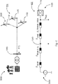
- FIG. 2 shows a schematic and exemplary structure of a wind farm 1000, in particular in the form of an equivalent circuit diagram.
- the wind farm 1000 has a large number of wind energy installations 1100 which are connected to one another via a common wind farm network 1200 .
- the wind farm 1000 is connected to an electrical supply network 2000 via a grid connection point 1300 and is controlled by a wind farm control unit 1400 which preferably has a look-up table 1410 .
- the wind turbines 1000 (WEA_i for short) are controlled by the wind farm control unit 1400 via a wind turbine control unit, e.g. by means of a reactive power setpoint value Q_SOLL_WEA_i and thereby generate an active electrical power P_WEA_i and a reactive electrical power Q_WEA_i.
- This active and reactive power P_WEA_i, Q_WEA_i generated in this way is fed into the electrical wind farm network 1200 with losses via a converter, i.e. the converter generates a converter loss P_V_LS_i.
- each wind turbine also has an available power P_AVAIL_WEA_i, which can also be referred to as the available wind turbine power.
- the available wind turbine power P_AVAIL_WEA_i is mostly above the power generated P_WEA_i.
- the power P_WEA_i, Q_WEA_i generated by the wind turbines 1100 is fed into the electrical supply network 2000 with losses via the electrical wind farm network 1200, and in particular at the network connection point 1300 via a transformer, in the form of a wind farm current I_NVP, i.e. in particular that the wind farm network has a reactive power requirement Q_PARK_ZUS with a loss line P_V_PARK.
- the wind farm network itself can be described by a wind farm resistance R_PARK, jX_PARK.
- a wind farm control unit 1400 is used to control the wind farm 1000, which is set up to communicate with the individual wind power plants via the wind power plant control unit and to transfer this target value, such as a reactive power target value Q_SOLL_WEA_i.
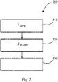
- FIG 3 shows schematically and as an example the sequence 300 of a method for determining a power loss of a wind farm, in particular as in FIG 2 shown.
- a current to be fed in by the wind farm at the grid connection point is determined, for example from a target value.
- a wind farm resistance of the wind farm through which the current to be fed flows is determined, for example using characteristics of the wind farm.
- the power loss of the wind farm is determined taking into account the current to be fed in and the wind farm resistance.
- FIG. 4 shows a schematic and exemplary simplified equivalent circuit diagram of a wind farm, such as in 2 shown.
- the upper part 410 shows a technical depiction of a wind farm 1000 with a large number of wind turbines 1100, which is connected to the electrical supply network 2000 via a network connection point 1300 on a transformer.
- the grid connection point 1300 is preferably specified by the grid operator, for example upstream, downstream or in the transformer.
- the wind farm resistance Z_PARK preferably from the low-voltage side U_NS of the wind turbine, in particular at the output of the converter 1110, to the grid connection point 1300, and preferably the impedance Z_grid of the superimposed grid, are taken into account.
- the power loss of the wind farm P_V_GES is thus determined in particular from the power loss of the wind farm network P_V_PARK and the additional converter losses of the wind energy installations P_V_LS_i. The whole thing takes place in particular using the reactive charging power Q_KAP of the wind farm, preferably with an active power of zero.
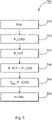
- figure 5 shows schematically and by way of example the sequence 500 of a method for determining an available power in one embodiment.
- a first step 510 an equivalent circuit diagram for the wind farm is determined.
- the power loss of the wind farm is determined, preferably as described above.
- step 530 the maximum possible output of the wind farm is described, taking into account a prevailing wind.
- step 540 the available power of the wind farm is determined.
- the power loss is subtracted from the maximum possible output of the wind farm.
- the power determined from this is reported to the network operator or made available in a further step 550, taking into account further losses.
- this state is stored in a further step 560, for example in order to iteratively execute one of the methods described above.
Landscapes
- Engineering & Computer Science (AREA)
- Power Engineering (AREA)
- Life Sciences & Earth Sciences (AREA)
- Sustainable Development (AREA)
- Sustainable Energy (AREA)
- Chemical & Material Sciences (AREA)
- Combustion & Propulsion (AREA)
- Mechanical Engineering (AREA)
- General Engineering & Computer Science (AREA)
- Supply And Distribution Of Alternating Current (AREA)
- Control Of Eletrric Generators (AREA)
Priority Applications (1)
| Application Number | Priority Date | Filing Date | Title |
|---|---|---|---|
| EP20217430.6A EP4020742A1 (fr) | 2020-12-28 | 2020-12-28 | Procédé de détermination d'une puissance de perte |
Applications Claiming Priority (1)
| Application Number | Priority Date | Filing Date | Title |
|---|---|---|---|
| EP20217430.6A EP4020742A1 (fr) | 2020-12-28 | 2020-12-28 | Procédé de détermination d'une puissance de perte |
Publications (1)
| Publication Number | Publication Date |
|---|---|
| EP4020742A1 true EP4020742A1 (fr) | 2022-06-29 |
Family
ID=74194471
Family Applications (1)
| Application Number | Title | Priority Date | Filing Date |
|---|---|---|---|
| EP20217430.6A Pending EP4020742A1 (fr) | 2020-12-28 | 2020-12-28 | Procédé de détermination d'une puissance de perte |
Country Status (1)
| Country | Link |
|---|---|
| EP (1) | EP4020742A1 (fr) |
Citations (3)
| Publication number | Priority date | Publication date | Assignee | Title |
|---|---|---|---|---|
| DE102011112025A1 (de) * | 2011-08-31 | 2013-02-28 | Repower Systems Se | Schnelle Spannungsregelung |
| US20150267683A1 (en) * | 2014-03-18 | 2015-09-24 | General Electric Company | Method for operating a wind farm and wind farm |
| ES2647217T3 (es) * | 2007-12-20 | 2017-12-20 | Vestas Wind Systems A/S | Método para controlar una salida común de al menos dos turbinas eólicas, un sistema de control de turbina eólica central, un parque eólico y un grupo de parques eólicos |
-
2020
- 2020-12-28 EP EP20217430.6A patent/EP4020742A1/fr active Pending
Patent Citations (3)
| Publication number | Priority date | Publication date | Assignee | Title |
|---|---|---|---|---|
| ES2647217T3 (es) * | 2007-12-20 | 2017-12-20 | Vestas Wind Systems A/S | Método para controlar una salida común de al menos dos turbinas eólicas, un sistema de control de turbina eólica central, un parque eólico y un grupo de parques eólicos |
| DE102011112025A1 (de) * | 2011-08-31 | 2013-02-28 | Repower Systems Se | Schnelle Spannungsregelung |
| US20150267683A1 (en) * | 2014-03-18 | 2015-09-24 | General Electric Company | Method for operating a wind farm and wind farm |
Non-Patent Citations (1)
| Title |
|---|
| GUPTA AKHILESH PRAKASH ET AL: "Apparent Power Loss Based Equivalent Model of Wind Farm Collector System", 2018 20TH NATIONAL POWER SYSTEMS CONFERENCE (NPSC), IEEE, 14 December 2018 (2018-12-14), pages 1 - 6, XP033578938, DOI: 10.1109/NPSC.2018.8771713 * |
Similar Documents
| Publication | Publication Date | Title |
|---|---|---|
| EP2994971B1 (fr) | Procédé d'injection d'une puissance électrique dans un réseau de distribution électrique | |
| EP2873129B1 (fr) | Procédé et dispositif pour injecter de l'énergie électrique dans un réseau d'alimentation électrique | |
| EP2872777B1 (fr) | Procédé pour commander un générateur électrique | |
| EP3008334B1 (fr) | Procédé pour injecter une puissance électrique dans un réseau de distribution électrique | |
| EP2659137B1 (fr) | Parc éolien et procédé permettant d'exploiter un parc éolien | |
| DE102012212777A1 (de) | Verfahren zum Steuern eines Windparks | |
| WO2006056404A1 (fr) | Procede pour optimaliser le fonctionnement d'installations d'energie eolienne | |
| DE102013208410A1 (de) | Verfahren zum Einspeisen elektrischer Leistung in ein elektrisches Versorgungsnetz | |
| DE102013222452A1 (de) | Verfahren zum Betreiben einer Windenergieanlage | |
| DE102012220582A1 (de) | Windenergieanlage und Verfahren zum Einspeisen elektrischer Energie | |
| EP3839251A1 (fr) | Optimisation d'un parc éolien | |
| EP3033816B1 (fr) | Procédé permettant d'injecter de l'énergie électrique dans un réseau d'alimentation | |
| DE102006021982C5 (de) | Gestaffelt abschaltbarer Windpark | |
| DE102014115119A1 (de) | Verfahren und System zum Überwachen einer Netzspannung in einem Niederspannungsnetz | |
| DE102018125529A1 (de) | Dynamisches Windkraftwerk | |
| DE102014101809A1 (de) | Verfahren zur Steuerung einer regenerativen Energieerzeugungsanlage und Regenerative Energieerzeugungsanlage | |
| DE102008037566A1 (de) | Vorrichtung zur Regelung einer doppelt gespeisten Asynchronmaschine | |
| EP3751691B1 (fr) | Système d'alimentation électrique | |
| WO2019211034A1 (fr) | Procédé de régulation en temps réel d'un système d'alimentation et de distribution d'énergie | |
| EP4020742A1 (fr) | Procédé de détermination d'une puissance de perte | |
| EP3345279A1 (fr) | Procédé d'injection de puissance électrique | |
| EP4020739A1 (fr) | Procédé de détermination d'une puissance de perte | |
| EP4508733A1 (fr) | Procédé et dispositif de détermination d'une séquence de récupération de réserves de fonctionnement à partir d'une pluralité d'installations pour fournir une réserve de fonctionnement totale | |
| EP4084259A1 (fr) | Procédé et système d'énergie éolienne permettant d'injecter de l'énergie électrique dans un réseau d'alimentation électrique | |
| EP3836336A1 (fr) | Dispositif et procédé de stabilisation angulaire d'une machine virtuelle synchrone |
Legal Events
| Date | Code | Title | Description |
|---|---|---|---|
| PUAI | Public reference made under article 153(3) epc to a published international application that has entered the european phase |
Free format text: ORIGINAL CODE: 0009012 |
|
| STAA | Information on the status of an ep patent application or granted ep patent |
Free format text: STATUS: THE APPLICATION HAS BEEN PUBLISHED |
|
| AK | Designated contracting states |
Kind code of ref document: A1 Designated state(s): AL AT BE BG CH CY CZ DE DK EE ES FI FR GB GR HR HU IE IS IT LI LT LU LV MC MK MT NL NO PL PT RO RS SE SI SK SM TR |
|
| STAA | Information on the status of an ep patent application or granted ep patent |
Free format text: STATUS: REQUEST FOR EXAMINATION WAS MADE |
|
| 17P | Request for examination filed |
Effective date: 20230102 |
|
| RBV | Designated contracting states (corrected) |
Designated state(s): AL AT BE BG CH CY CZ DE DK EE ES FI FR GB GR HR HU IE IS IT LI LT LU LV MC MK MT NL NO PL PT RO RS SE SI SK SM TR |
|
| STAA | Information on the status of an ep patent application or granted ep patent |
Free format text: STATUS: EXAMINATION IS IN PROGRESS |
|
| 17Q | First examination report despatched |
Effective date: 20250711 |