EP3839416B1 - Dispositif de réduction d'erreurs d'un dispositif tournant lors de la détermination des valeurs mesurées des coordonnées d'une pièce - Google Patents
Dispositif de réduction d'erreurs d'un dispositif tournant lors de la détermination des valeurs mesurées des coordonnées d'une pièce Download PDFInfo
- Publication number
- EP3839416B1 EP3839416B1 EP19217913.3A EP19217913A EP3839416B1 EP 3839416 B1 EP3839416 B1 EP 3839416B1 EP 19217913 A EP19217913 A EP 19217913A EP 3839416 B1 EP3839416 B1 EP 3839416B1
- Authority
- EP
- European Patent Office
- Prior art keywords
- distance
- sensors
- rotary device
- detecting
- distance sensors
- Prior art date
- Legal status (The legal status is an assumption and is not a legal conclusion. Google has not performed a legal analysis and makes no representation as to the accuracy of the status listed.)
- Active
Links
Images



Classifications
-
- G—PHYSICS
- G01—MEASURING; TESTING
- G01B—MEASURING LENGTH, THICKNESS OR SIMILAR LINEAR DIMENSIONS; MEASURING ANGLES; MEASURING AREAS; MEASURING IRREGULARITIES OF SURFACES OR CONTOURS
- G01B21/00—Measuring arrangements or details thereof, where the measuring technique is not covered by the other groups of this subclass, unspecified or not relevant
- G01B21/02—Measuring arrangements or details thereof, where the measuring technique is not covered by the other groups of this subclass, unspecified or not relevant for measuring length, width, or thickness
- G01B21/04—Measuring arrangements or details thereof, where the measuring technique is not covered by the other groups of this subclass, unspecified or not relevant for measuring length, width, or thickness by measuring coordinates of points
- G01B21/045—Correction of measurements
-
- G—PHYSICS
- G01—MEASURING; TESTING
- G01B—MEASURING LENGTH, THICKNESS OR SIMILAR LINEAR DIMENSIONS; MEASURING ANGLES; MEASURING AREAS; MEASURING IRREGULARITIES OF SURFACES OR CONTOURS
- G01B11/00—Measuring arrangements characterised by the use of optical techniques
- G01B11/26—Measuring arrangements characterised by the use of optical techniques for measuring angles or tapers; for testing the alignment of axes
- G01B11/27—Measuring arrangements characterised by the use of optical techniques for measuring angles or tapers; for testing the alignment of axes for testing the alignment of axes
- G01B11/272—Measuring arrangements characterised by the use of optical techniques for measuring angles or tapers; for testing the alignment of axes for testing the alignment of axes using photoelectric detection means
-
- G—PHYSICS
- G01—MEASURING; TESTING
- G01B—MEASURING LENGTH, THICKNESS OR SIMILAR LINEAR DIMENSIONS; MEASURING ANGLES; MEASURING AREAS; MEASURING IRREGULARITIES OF SURFACES OR CONTOURS
- G01B7/00—Measuring arrangements characterised by the use of electric or magnetic techniques
- G01B7/30—Measuring arrangements characterised by the use of electric or magnetic techniques for measuring angles or tapers; for testing the alignment of axes
- G01B7/31—Measuring arrangements characterised by the use of electric or magnetic techniques for measuring angles or tapers; for testing the alignment of axes for testing the alignment of axes
Definitions
- the invention relates to an arrangement for reducing errors of a rotating device when determining coordinate measuring machines of a workpiece.
- the measured values show a significantly higher waviness, which is not caused by the material surface, but by the rotary table behavior.
- this angular error is known in amplitude and phase position (related to the input angle and output angle), it can be taken into account in the execution of a measuring line in conjunction with the usual geometric correction algorithms of a coordinate measuring machine.
- a coordinate measuring machine with linear axes, wherein a carriage is provided which can be moved in a first axial direction and is connected to a second linear axis which comprises a second carriage which can be moved in a second axial direction which is essentially perpendicular to the first axial direction.
- a light source is provided for generating a light beam parallel to the first axial direction and at least one position-sensitive sensor assigned to the first axis for detecting a position of an impact area of the light beam parallel to the first axial direction.
- the state of the art ( DE 10 2010 052 503 B4 ) a method for controlling a coordinate measuring machine with a plurality of motor-driven axes for positioning a probe, wherein the coordinate measuring machine is moved in at least one axis and wherein a deformation of the coordinate measuring machine is measured.
- a method for controlling a coordinate measuring machine with a plurality of motor-driven axes for positioning a probe wherein the coordinate measuring machine is moved in at least one axis and wherein a deformation of the coordinate measuring machine is measured.
- DE 101 27 528 A1 also includes a device for detecting the rotational movement of an element that can be rotated about an axis, in particular a rotary table with a measuring element arranged coaxially to the element and two measuring graduations provided on the measuring element, which surround the axis of rotation of the measuring element in a ring shape and which are designed to scan along two linearly independent directions.
- a device for detecting the rotational movement of an element that can be rotated about an axis in particular a rotary table with a measuring element arranged coaxially to the element and two measuring graduations provided on the measuring element, which surround the axis of rotation of the measuring element in a ring shape and which are designed to scan along two linearly independent directions.
- the state of the art ( DE 10 2005 023 467 A1 ) a device for rotating a body and a method for monitoring a load-related wobble movement of a rotary table loaded with a body.
- current wobble movement data are determined while the rotary table is rotating over a predetermined angular range, from which values of a wobble error can be determined.
- the values of a wobble error determined for the unloaded rotary table are reproduced using wobble error comparison data and data describing a load-related wobble error are determined.
- This method does not detect an incorrect displacement of the axis or the position error of the rotary table that results from the load.
- This method is very time-consuming because the rotary table is repeatedly rotated by 360° when the load changes, which is determined via an acceleration sensor. must be determined in order to determine the wobble error as a complete correction using the angle sensors provided. Both are derived from a previously recorded correction.
- the state of the art ( DE 10 2013 204 581 A1 ) a method for correcting an angular deviation when operating a coordinate measuring machine.
- the correction values are determined for different loads and temperatures.
- the angle changes for the different states are determined in advance and not directly online. Position shifts are also not determined.
- the state of the art ( DE 10 2015 201 583 A1 ) a method for determining a moment acting on a rotating device or a force acting on a rotating device.
- a moment and/or a force is generated.
- a deflection of the rotor and/or a position error of the rotor is then determined and the moment and/or the force is determined from this.
- This method is used to be able to issue a warning and/or prevent a rotational movement of the rotor when a predetermined limit value of the moment and/or the force is reached or exceeded.
- the technical problem underlying the invention is to provide a device for reducing errors of a rotary device when determining coordinate measurement values of a workpiece, with which rotary table errors, for example translational deviations or Wobble can be detected without prior measurement with a test specimen and the coordinate measurement values can be corrected.
- the arrangement according to the invention for reducing errors of a rotary device when determining coordinate measurement values of a workpiece wherein the arrangement comprises a coordinate measuring machine and the rotary device on which a workpiece can be arranged and rotated about a rotation axis of the rotary device, wherein the rotary device with a turntable plate has a first part that is stationary with respect to the coordinate measuring machine during a measurement and a second part that is rotatable relative to the first part, is characterized in that at least three distance sensors for detecting a distance of the rotatable second part to the at least three distance sensors are arranged on the stationary first part.
- the distance sensors are designed as distance sensors which detect the distance in the radial direction relative to a rotation axis of the rotating device and/or as distance sensors which detect the distance in the axial direction relative to the rotation axis of the rotating device, and that the distance sensors are designed as distance sensors of a rotating table plate which determine a distance between the distance sensors and the rotating table plate.
- the inventive design of the arrangement makes it possible to detect translational distances of the rotary device, in particular a rotary table plate of the rotary table device, from a fixed reference plane. For example, if the rotary table has a translational displacement or wobbles or bends, for example, due to a very heavy workpiece, these errors of the rotary table can be detected online using the at least three distance sensors and the coordinate measurement values can be corrected.
- the arrangement according to the invention has the advantage that the wobble and/or translational movements of the turntable plate, i.e. of the rotatable second part of the rotary device, can be detected during the measurement and, if necessary, corrected.
- the translational movements and/or the wobble are recorded online and the coordinate measurements are corrected immediately.
- Errors that cannot be detected with a test specimen can also be corrected. These errors include, for example, errors that occur when very heavy workpieces are placed on the turntable and the turntable plate bends. These measured values cannot be detected with a test specimen measurement.
- the arrangement according to the invention has the advantage of saving time since test specimen measurements can be omitted.
- three distance sensors are sufficient.
- all three distance sensors are advantageously designed as distance sensors that measure the distance in either the radial direction or the axial direction relative to the axis of rotation of the rotating device.
- four distance sensors are provided for detecting the distance in the radial direction relative to the axis of rotation of the rotating device.
- four distance sensors can be provided for detecting the distance in the axial direction relative to the axis of rotation of the rotating device.
- a further advantageous embodiment provides that four distance sensors for detecting the distance in the radial direction relative to the axis of rotation of the rotary device and four distance sensors for detecting the distance in the axial direction relative to the axis of rotation of the rotating device.
- the embodiment with the four distance sensors for detecting the distance in the radial direction relative to the axis of rotation of the rotary device has the advantage that displacements that only arise due to possible inaccuracies of the rotary table plate are not detected, but that the sensors can be used to determine whether there is actually a translational movement of the rotary table plate.
- the arrangement of four distance sensors for detecting the distance in the axial direction relative to the rotation axis of the rotary device also prevents inaccuracies in the rotary table plate from being detected.
- wobble can be detected because in the case of wobble, i.e. when the rotary table plate tilts towards the rotation axis of the rotary device, the rotary table plate has a smaller distance to a distance sensor on one side and a correspondingly larger distance to the distance sensor on the opposite side relative to the diameter of the rotary table plate.
- a particularly preferred embodiment of the invention provides that four distance sensors are provided for detecting the distance in the radial direction relative to the axis of rotation of the rotating device and four distance sensors are provided for detecting the distance in the axial direction relative to the axis of rotation of the rotating device.
- the distance sensors are evenly distributed over the circumference of the rotating device.
- the sensors are advantageously arranged at an angle of 120° to each other.
- a further advantageous embodiment of the invention provides that a distance sensor for detecting the distance in the radial direction of the axis of rotation of the rotating device and a distance sensor for detecting the distance in the axial direction relative to the axis of rotation of the rotating device are arranged at the same angular positions on the first stationary part of the rotating device as seen over the circumference of the rotating device.
- the distance sensors for detecting the distance in the axial direction and in the radial direction relative to the axis of rotation of the rotating device are arranged, for example, at 0°, 90°, 180° and 270°.
- This paired arrangement of the distance sensors for detecting the distance in the axial and radial direction relative to the rotation axis of the rotary device has the advantage that that the wiring effort for the distance sensors can be kept to a minimum.
- a further advantageous embodiment of the invention provides that two distance sensors for detecting the distance in the radial direction relative to the axis of rotation of the rotary device are arranged offset from one another by 180° around the circumference of the rotary device. These distance sensors arranged opposite one another ensure that displacements are not only caused by inaccuracies in the rotary table plate.
- Inductive sensors capacitive sensors, piezoelectric sensors, eddy current sensors, magnetic field sensors, optical sensors and/or mechanical inductive sensors are advantageously used as distance sensors. Other sensors with which a distance measurement can be carried out can also be used.
- Inductive sensors have the advantage that they are very inexpensive.
- a further advantageous embodiment of the invention provides that the first stationary part of the rotary device is part of the coordinate measuring machine.
- the rotary device is integrated with the rotary table in the coordinate measuring machine, for example in the measuring table of the coordinate measuring machine.
- the distance sensors are arranged on the measuring table of the coordinate measuring machine.
- the coordinate measuring machine is designed as a coordinate measuring machine with a tool table and that the rotating device is arranged on the tool table.
- the rotating device consists of the stationary part and the part that can be rotated relative to the stationary part.
- the distance sensors are arranged on the stationary part.
- the coordinate measuring machine it is possible for the coordinate measuring machine to be designed as a gantry-type coordinate measuring machine. However, it is also possible to design the coordinate measuring machine in a different way.
- Fig. 1 shows a coordinate measuring machine 1 in a gantry design with a base bed 2 on which a measuring table 3 is arranged so that it can be moved in the X direction.
- guides 4 are arranged on the base bed.
- a gantry 5, which has supports 6 and which is not designed to be movable, carries a carriage 8 on a crossbeam 7 that can be moved in the Y direction, on which a sleeve 9 is arranged so that it can be moved in the Z direction.
- the sleeve 9 carries a probe head 10 on which a probe ball 12 is arranged.
- the probe 10 can be exchanged for other probe combinations (not shown).
- a rotary table 11 is arranged in the measuring table 3, on which a workpiece (not shown) can be arranged.
- the rotary table 11 is rotated and at the same time the probe 12 is moved and aligned in such a way that the contour of a workpiece surface can be determined by scanning.
- a wobble or translational displacements of the rotary table 11 are included in the coordinate measurement values.
- the rotating device i.e. the rotary table 11
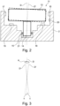
- the rotary table 11 consists of a rotary table plate 13 and a rotary table base 14.
- the rotary table base 14 is mounted in ball bearings 15 such that the rotary table plate 13 and the rotary table base 14 can rotate about the axis of rotation D.
- the ball bearings 15 and the rotary table base 14 are only shown schematically. In practice, the rotary table base is significantly shorter and wider in order to largely counteract any wobbling movement of the rotary table plate 13.
- the bearings 15 are arranged in the base bed 2. Likewise, distance sensors 16, 17, 18, 19 are fixedly arranged on the stationary part, i.e. on the base bed 2.
- the sensors 16, 17 are designed as distance sensors 16, 17 that measure the distance in the radial direction relative to the rotation axis D of the rotary device 11.
- the distance sensors 18, 19 are designed as distance sensors 18, 19 that measure the distance in the axial direction relative to the rotation axis D of the rotary device 11.
- the turntable 13 with the turntable base 14 is aligned with the solid line in the ideal position, i.e. the axis of rotation D is vertical.
- the rotary table 11 wobbles, that is, the rotation axis D' moves at an angle around the rotation axis D.
- This wobble is in Fig. 3
- the rotation axis D is vertically aligned.
- the rotation axis D' which indicates the wobbling of the rotation axis D', moves around the rotation axis D, as shown in the upper part of the picture with the arrow A.
- the angular deviation between D and D' is ⁇ .
- the wobble of the turntable plate 13 causes the distance between the turntable plate 13 and the distance sensor 17 to increase in the radial direction relative to the axis of rotation D, while the distance between the turntable plate 13 and the distance sensor 16 to decrease in the radial direction relative to the axis of rotation D.
- the distance sensors 16, 17 can be used to determine whether either a translational movement or a wobbling movement is taking place. Local inaccuracies in the rotary table plate 13 can be ruled out because the distances between the rotary table plate 13 and the distance sensors 16, 17 change in each case.
- the distance between the turntable plate 13 and the distance sensors 18, 19 changes.
- the distance between the turntable plate 13 and the distance sensor 19 becomes larger, while the distance between the turntable plate 13 and the distance sensor 18 becomes smaller.
- the distance sensors 18, 19 detect the distance in the axial direction relative to the turntable axis D.
- the wobble can be determined based on the values of the four distance sensors 16, 17, 18, 19. These measured values are used online to correct the coordinate measured values of a workpiece (not shown) arranged on the rotary table 11.
- FIG. 2 A position measuring device, i.e. a rotation angle measuring device 20, is shown schematically, which determines the rotation angle of the turntable 11.
- a drive 21 is shown only schematically, which drives the turntable such that the turntable 11 rotates about the axis of rotation D.
- Fig. 4 the rotating device 11 is shown with the rotary table plate 13 and the rotary table base 14.
- the rotary table plate 13 is shown in the ideal position with a dashed line.
- a solid line shows a bend in the rotary table plate 13 on the right-hand side. This bend can be caused, for example, by a heavy workpiece (not shown).
- Fig. 4 parts shown, which are also in Fig. 2 are provided with the same reference numbers and will not be described again.
- the bending of the turntable plate 13 changes the distance between the turntable plate 13 and the distance sensor 18.
- the distance between the turntable plate 13 and the sensor 18 which detects the distance in the axial direction relative to the axis of rotation D of the rotating device 11 decreases. This is detected by the distance sensor 18.
- the distance sensor 19 detects a corresponding reduction in the distance between the turntable plate 13 and the distance sensor 19 in the axial direction relative to the axis of rotation D.
- These measured values can be used to correct the coordinate measured values of the workpiece online.
- Fig. 5 shows the rotary table plate 13.
- the coordinate measuring machine with the base bed 2 is in Fig. 5 not shown.
- the sensors 16, 17, 18, 19 as well as the other sensors 22, 23, 24, 25 are connected to the Fig. 5 not shown base bed 2 or on a stationary part of the rotating device 11 with the turntable plate 13.
- the distance sensors 16, 17, 22, 23 are designed as distance sensors that detect the distance in the radial direction relative to the axis of rotation D of the rotating device 11.
- the distance sensors 18, 19, 24, 25 are designed as distance sensors that detect the distance in the axial direction relative to the axis of rotation D of the rotating device 11.
- the distance sensors 22, 16, 23, 17 are each arranged at an angle of 90° to one another.
- the turntable rotates in the direction of the double arrow B. Assuming that the distance sensor 22 is arranged at 0°, the distance sensor 16 is arranged at 90°, the distance sensor 23 at 180° and the distance sensor 17 at 270°.
- the distance sensors 18, 19, 24, 25 are also each arranged at a 90° angle with respect to the direction of rotation of the turntable plate B.
- the distance sensor 24 is arranged at 0°, the distance sensor at 90°, the distance sensor 25 at 180° and the distance sensor 19 at 270°.
- the distance sensors 22, 24; 16, 18; 23, 25; 17, 19; form sensor pairs, with one sensor in the radial direction and one sensor in the axial direction relative to the axis of rotation D detecting the distance to the turntable plate 13.
- a translational movement is shown by arrow C in Fig. 5
- the rotary table plate 13 moves in the direction of arrow C.
- the distance between the rotary table plate 13 and the distance sensor 17 becomes larger, while the distance between the rotary table plate 13 and the distance sensor 16 becomes smaller.
- the effective direction of the distance sensors 16, 23; 17, 22 are shown with arrows E.
Landscapes
- Physics & Mathematics (AREA)
- General Physics & Mathematics (AREA)
- Length Measuring Devices With Unspecified Measuring Means (AREA)
- A Measuring Device Byusing Mechanical Method (AREA)
Claims (8)
- Ensemble destiné à réduire des erreurs d'un dispositif de rotation lors de la détermination de valeurs de mesure de coordonnées d'une pièce, l'ensemble comportant un appareil de mesure de coordonnées et le dispositif de rotation sur lesquels une pièce peut être disposée et mise en rotation sur un axe de rotation du dispositif de rotation, le dispositif de rotation pourvu d'un plateau tournant comportant une première partie qui est fixe par rapport à l'appareil de mesure de cordonnées pendant une mesure et une deuxième partie qui peut tourner par rapport à la première partie,au moins trois capteurs de distance (16, 17, 18, 19, 22, 23, 24, 25) destinés à détecter la distance entre la deuxième partie rotative (13) et les au moins trois capteurs de distance (16, 17, 18, 19, 22, 23, 24, 25) étant disposés sur la première partie fixe, et les capteurs de distance (16, 17, 18, 19, 22, 23, 24, 25) étant conçus comme des capteurs de distance (16, 17, 18, 19, 22, 23, 24, 25) qui détectent la distance par rapport à l'axe de rotation (D) du dispositif de rotation (11) dans la direction radiale et/ou qui détectent la distance par rapport à l'axe de rotation (D) du dispositif de rotation (11) dans la direction axiale,caractérisé en ce que les capteurs de distance (16, 17, 18, 19, 22, 23, 24, 25) sont conçus comme des capteurs de distance (16, 17, 18, 19, 22, 23, 24, 25) qui déterminent la distance entre les capteurs de distance (16, 17, 18, 19, 22, 23, 24, 25) et le plateau tournant (13) .
- Ensemble selon la revendication 1, caractérisé en ce que quatre capteurs de distance (16, 17, 22, 23) sont prévus pour détecter la distance de la deuxième partie rotative (13) dans la direction radiale par rapport à l'axe de rotation (D) du dispositif de rotation (11) et/ou quatre capteurs de distance (18, 19, 24, 25) sont prévus pour détecter la distance de la deuxième partie rotative (13) dans la direction axiale par rapport à l'axe de rotation (D) du dispositif de rotation (11).
- Ensemble selon la revendication 1 ou 2, caractérisé en ce que les capteurs de distance (16, 17, 22, 23 ; 18, 19, 24, 25) sont disposés de manière uniformément répartie sur la circonférence du dispositif de rotation.
- Ensemble selon la revendication 2, caractérisé en ce qu'un capteur de distance (16, 17, 22, 23) destiné à détecter la distance de la deuxième partie rotative (13) dans la direction radiale par rapport à l'axe de rotation (D) du dispositif de rotation (11) et un capteur de distance (18, 19, 24, 25) destiné à détecter la distance de la deuxième partie rotative (13) dans la direction axiale par rapport à l'axe de rotation (D) du dispositif de rotation (11), sont disposés, en vue de dessus de la circonférence du dispositif de rotation (11), aux mêmes positions angulaires sur la première partie fixe (2) du dispositif de rotation (11).
- Ensemble selon l'une des revendications précédentes, caractérisé en ce que deux capteurs de distance (16, 17 ; 22, 23) destinés à détecter la distance de la deuxième partie rotative (13) dans la direction radiale par rapport à l'axe de rotation (D) du dispositif de rotation (11) sont disposés de manière décalée de 180° l'un par rapport à l'autre sur la circonférence du dispositif de rotation (11).
- Ensemble selon l'une des revendications précédentes, caractérisé en ce que des capteurs inductifs, des capteurs capacitifs, des capteurs piézoélectriques, des capteurs à courants de Foucault, des capteurs de champ magnétique, des capteurs optiques et/ou des boutons inductifs mécaniques peuvent être utilisés comme capteurs de distance (16, 17, 18, 19, 22, 23, 24, 25).
- Ensemble selon l'une des revendications précédentes, caractérisé en ce que la première partie fixe (2) du dispositif de rotation (11) fait partie de l'appareil de mesure de coordonnées (1).
- Ensemble selon l'une des revendications 1 à 6, caractérisé en ce que l'appareil de mesure de coordonnées (1) est conçu comme un appareil de mesure de coordonnées (1) pourvu d'une table à outils (3), et en ce que le dispositif de rotation (11) est disposé sur la table à outils (3).
Priority Applications (2)
| Application Number | Priority Date | Filing Date | Title |
|---|---|---|---|
| EP19217913.3A EP3839416B1 (fr) | 2019-12-19 | 2019-12-19 | Dispositif de réduction d'erreurs d'un dispositif tournant lors de la détermination des valeurs mesurées des coordonnées d'une pièce |
| ES19217913T ES2993031T3 (en) | 2019-12-19 | 2019-12-19 | Arrangement for reducing errors in a rotating device during the determination of coordinate measurements of a workpiece |
Applications Claiming Priority (1)
| Application Number | Priority Date | Filing Date | Title |
|---|---|---|---|
| EP19217913.3A EP3839416B1 (fr) | 2019-12-19 | 2019-12-19 | Dispositif de réduction d'erreurs d'un dispositif tournant lors de la détermination des valeurs mesurées des coordonnées d'une pièce |
Publications (2)
| Publication Number | Publication Date |
|---|---|
| EP3839416A1 EP3839416A1 (fr) | 2021-06-23 |
| EP3839416B1 true EP3839416B1 (fr) | 2024-11-06 |
Family
ID=69156151
Family Applications (1)
| Application Number | Title | Priority Date | Filing Date |
|---|---|---|---|
| EP19217913.3A Active EP3839416B1 (fr) | 2019-12-19 | 2019-12-19 | Dispositif de réduction d'erreurs d'un dispositif tournant lors de la détermination des valeurs mesurées des coordonnées d'une pièce |
Country Status (2)
| Country | Link |
|---|---|
| EP (1) | EP3839416B1 (fr) |
| ES (1) | ES2993031T3 (fr) |
Family Cites Families (9)
| Publication number | Priority date | Publication date | Assignee | Title |
|---|---|---|---|---|
| DE3637410A1 (de) | 1986-11-03 | 1988-05-11 | Zeiss Carl Fa | Verfahren zur messung von drehtischabweichungen |
| US6964102B2 (en) | 2000-09-18 | 2005-11-15 | Dr. Johannes Heidenhain Gmbh | Device and method for detecting the rotational movement of an element rotatably mounted about an axis |
| DE102005023467B4 (de) | 2005-05-20 | 2021-09-09 | Carl Zeiss Industrielle Messtechnik Gmbh | Vorrichtung zur Drehung eines Körpers und Verfahren zur Überwachung einer lastbedingten Taumelbewegung eines mit einem Körper belasteten Drehtischs |
| DE102009044640A1 (de) | 2008-12-04 | 2010-07-01 | Hexagon Metrology Gmbh | Koordinatenmessgerät |
| DE102010052503B4 (de) | 2010-11-26 | 2012-06-21 | Wenzel Scantec Gmbh | Verfahren zur Steuerung eines Koordinatenmessgeräts sowie Koordinatenmessgerät |
| CN103827637B (zh) * | 2011-07-08 | 2016-02-24 | 卡尔蔡司工业测量技术有限公司 | 旋转装置的校准和运行、尤其是用于使坐标测量仪的探触头和/或探触件旋转的旋转装置的校准和运行 |
| DE102012012197B4 (de) | 2012-05-02 | 2016-10-13 | Wenzel Präzision GmbH | Koordinatenmessgerät sowie Verfahren zum Betreiben eines Koordinatenmessgeräts |
| DE102013204581A1 (de) | 2013-03-15 | 2014-09-18 | Carl Zeiss Industrielle Messtechnik Gmbh | Verfahren zur Korrektur einer Winkelabweichung beim Betrieb eines Koordinatenmessgeräts |
| DE102015201583B4 (de) * | 2015-01-29 | 2018-07-26 | Carl Zeiss Industrielle Messtechnik Gmbh | Verfahren zur Ermittlung eines auf eine Drehvorrichtung einwirkenden Moments oder einer auf eine Drehvorrichtung einwirkenden Kraft |
-
2019
- 2019-12-19 ES ES19217913T patent/ES2993031T3/es active Active
- 2019-12-19 EP EP19217913.3A patent/EP3839416B1/fr active Active
Also Published As
| Publication number | Publication date |
|---|---|
| EP3839416A1 (fr) | 2021-06-23 |
| ES2993031T3 (en) | 2024-12-20 |
Similar Documents
| Publication | Publication Date | Title |
|---|---|---|
| EP3049758B1 (fr) | Réduction d'erreurs d'un dispositif de rotation qui est utilisée lors de la détermination de coordonnées d'une pièce ou lors de l'usinage d'une pièce | |
| EP2834595B1 (fr) | Méthode et appareil pour la réduction des erreurs associées à un dispositif de rotation lors de la détermination des coordonnées d'une pièce ou lors de l'usinage d'une pièce | |
| DE102013216093B4 (de) | Reduzieren von Fehlern einer Drehvorrichtung, insbesondere für die Bestimmung von Koordinaten eines Werkstücks oder die Bearbeitung eines Werkstücks | |
| EP2984442B1 (fr) | Procédé permettant de déterminer un contour d'un objet à mesurer | |
| EP2807447B1 (fr) | Procédé de détermination d'une valeur de correction pour un contrôle d'un palier à fluide, et machine présentant au moins un palier à fluide | |
| DE60132073T3 (de) | Vorrichtung und verfahren zum messen der dimensions- und formabweichung von kurbelzapfen am ort des schleifens | |
| DE69619857T2 (de) | Oberflächenformvermessung | |
| EP2378242B1 (fr) | Dispositif et procédé de mesure de forages | |
| EP2668464B1 (fr) | Dispositif de réglage et/ou de mesure | |
| EP0769677A2 (fr) | Procédé pour la mesure de coordonnées d'objets | |
| EP1322918B1 (fr) | Procede et dispositif pour detecter le mouvement de rotation d'un element monte en rotation autour d'un axe | |
| EP2053345B1 (fr) | Dispositif de mesure pour pièces à usiner lourdes | |
| EP2769172B1 (fr) | Procédé de mesurage d'un objet en trois dimensions | |
| EP1366394A2 (fr) | Procede et dispositif pour la mesure et l'usinage de pieces | |
| DE3320983A1 (de) | Transportables geraet zur pruefung des zahnflankenprofils und der zahnflankenlinien (zahnschraege) von zahnraedern auf verzahnmaschinen oder zahnflankenschleifmaschinen sowie zur positionierung dieses geraetes und zum orientieren des messtasters an der verzahnung fuer den messvorgang | |
| DE4412682A1 (de) | Vorrichtung zum Vermessen exzentrisch umlaufender Werkstücke | |
| EP3839416B1 (fr) | Dispositif de réduction d'erreurs d'un dispositif tournant lors de la détermination des valeurs mesurées des coordonnées d'une pièce | |
| DE102009044640A1 (de) | Koordinatenmessgerät | |
| DE102014116406B3 (de) | Verfahren zur Korrektur eines Getriebewinkelfehlers bei einem Drehtisch eines Messgeräts | |
| DE60032635T2 (de) | Verfahren und vorrichtung zum testen von werkzeugmaschinen | |
| EP4399046B1 (fr) | Machine-outil ayant un dispositif d'étalonnage pour étalonner un capteur de centrage | |
| DE102017222132B4 (de) | Sensor für ein Koordinatenmessgerät | |
| DE102020208567A1 (de) | Kalibrieren eines Referenzkörpers für die Führungsfehlerermittlung einer Maschinenachse | |
| EP3674033B1 (fr) | Procédé de détermination de la topographie d'une machine à outils | |
| DE202024107385U1 (de) | Werkzeugmaschineneinheit mit Prüfung von Lagerbelastungen der Spindel im Betrieb |
Legal Events
| Date | Code | Title | Description |
|---|---|---|---|
| PUAI | Public reference made under article 153(3) epc to a published international application that has entered the european phase |
Free format text: ORIGINAL CODE: 0009012 |
|
| STAA | Information on the status of an ep patent application or granted ep patent |
Free format text: STATUS: REQUEST FOR EXAMINATION WAS MADE |
|
| 17P | Request for examination filed |
Effective date: 20210208 |
|
| AK | Designated contracting states |
Kind code of ref document: A1 Designated state(s): AL AT BE BG CH CY CZ DE DK EE ES FI FR GB GR HR HU IE IS IT LI LT LU LV MC MK MT NL NO PL PT RO RS SE SI SK SM TR |
|
| STAA | Information on the status of an ep patent application or granted ep patent |
Free format text: STATUS: EXAMINATION IS IN PROGRESS |
|
| 17Q | First examination report despatched |
Effective date: 20211122 |
|
| GRAP | Despatch of communication of intention to grant a patent |
Free format text: ORIGINAL CODE: EPIDOSNIGR1 |
|
| STAA | Information on the status of an ep patent application or granted ep patent |
Free format text: STATUS: GRANT OF PATENT IS INTENDED |
|
| INTG | Intention to grant announced |
Effective date: 20240606 |
|
| GRAS | Grant fee paid |
Free format text: ORIGINAL CODE: EPIDOSNIGR3 |
|
| GRAA | (expected) grant |
Free format text: ORIGINAL CODE: 0009210 |
|
| STAA | Information on the status of an ep patent application or granted ep patent |
Free format text: STATUS: THE PATENT HAS BEEN GRANTED |
|
| AK | Designated contracting states |
Kind code of ref document: B1 Designated state(s): AL AT BE BG CH CY CZ DE DK EE ES FI FR GB GR HR HU IE IS IT LI LT LU LV MC MK MT NL NO PL PT RO RS SE SI SK SM TR |
|
| REG | Reference to a national code |
Ref country code: GB Ref legal event code: FG4D Free format text: NOT ENGLISH |
|
| REG | Reference to a national code |
Ref country code: CH Ref legal event code: EP |
|
| REG | Reference to a national code |
Ref country code: DE Ref legal event code: R096 Ref document number: 502019012429 Country of ref document: DE |
|
| REG | Reference to a national code |
Ref country code: IE Ref legal event code: FG4D Free format text: LANGUAGE OF EP DOCUMENT: GERMAN |
|
| REG | Reference to a national code |
Ref country code: ES Ref legal event code: FG2A Ref document number: 2993031 Country of ref document: ES Kind code of ref document: T3 Effective date: 20241220 |
|
| REG | Reference to a national code |
Ref country code: LT Ref legal event code: MG9D |
|
| REG | Reference to a national code |
Ref country code: NL Ref legal event code: MP Effective date: 20241106 |
|
| PG25 | Lapsed in a contracting state [announced via postgrant information from national office to epo] |
Ref country code: HR Free format text: LAPSE BECAUSE OF FAILURE TO SUBMIT A TRANSLATION OF THE DESCRIPTION OR TO PAY THE FEE WITHIN THE PRESCRIBED TIME-LIMIT Effective date: 20241106 Ref country code: IS Free format text: LAPSE BECAUSE OF FAILURE TO SUBMIT A TRANSLATION OF THE DESCRIPTION OR TO PAY THE FEE WITHIN THE PRESCRIBED TIME-LIMIT Effective date: 20250306 Ref country code: PT Free format text: LAPSE BECAUSE OF FAILURE TO SUBMIT A TRANSLATION OF THE DESCRIPTION OR TO PAY THE FEE WITHIN THE PRESCRIBED TIME-LIMIT Effective date: 20250306 |
|
| PG25 | Lapsed in a contracting state [announced via postgrant information from national office to epo] |
Ref country code: NL Free format text: LAPSE BECAUSE OF FAILURE TO SUBMIT A TRANSLATION OF THE DESCRIPTION OR TO PAY THE FEE WITHIN THE PRESCRIBED TIME-LIMIT Effective date: 20241106 Ref country code: FI Free format text: LAPSE BECAUSE OF FAILURE TO SUBMIT A TRANSLATION OF THE DESCRIPTION OR TO PAY THE FEE WITHIN THE PRESCRIBED TIME-LIMIT Effective date: 20241106 |
|
| PG25 | Lapsed in a contracting state [announced via postgrant information from national office to epo] |
Ref country code: BG Free format text: LAPSE BECAUSE OF FAILURE TO SUBMIT A TRANSLATION OF THE DESCRIPTION OR TO PAY THE FEE WITHIN THE PRESCRIBED TIME-LIMIT Effective date: 20241106 |
|
| PG25 | Lapsed in a contracting state [announced via postgrant information from national office to epo] |
Ref country code: NO Free format text: LAPSE BECAUSE OF FAILURE TO SUBMIT A TRANSLATION OF THE DESCRIPTION OR TO PAY THE FEE WITHIN THE PRESCRIBED TIME-LIMIT Effective date: 20250206 |
|
| REG | Reference to a national code |
Ref country code: GB Ref legal event code: 746 Effective date: 20250331 |
|
| PG25 | Lapsed in a contracting state [announced via postgrant information from national office to epo] |
Ref country code: GR Free format text: LAPSE BECAUSE OF FAILURE TO SUBMIT A TRANSLATION OF THE DESCRIPTION OR TO PAY THE FEE WITHIN THE PRESCRIBED TIME-LIMIT Effective date: 20250207 Ref country code: LV Free format text: LAPSE BECAUSE OF FAILURE TO SUBMIT A TRANSLATION OF THE DESCRIPTION OR TO PAY THE FEE WITHIN THE PRESCRIBED TIME-LIMIT Effective date: 20241106 |
|
| PG25 | Lapsed in a contracting state [announced via postgrant information from national office to epo] |
Ref country code: PL Free format text: LAPSE BECAUSE OF FAILURE TO SUBMIT A TRANSLATION OF THE DESCRIPTION OR TO PAY THE FEE WITHIN THE PRESCRIBED TIME-LIMIT Effective date: 20241106 |
|
| PG25 | Lapsed in a contracting state [announced via postgrant information from national office to epo] |
Ref country code: RS Free format text: LAPSE BECAUSE OF FAILURE TO SUBMIT A TRANSLATION OF THE DESCRIPTION OR TO PAY THE FEE WITHIN THE PRESCRIBED TIME-LIMIT Effective date: 20250206 |
|
| PG25 | Lapsed in a contracting state [announced via postgrant information from national office to epo] |
Ref country code: SM Free format text: LAPSE BECAUSE OF FAILURE TO SUBMIT A TRANSLATION OF THE DESCRIPTION OR TO PAY THE FEE WITHIN THE PRESCRIBED TIME-LIMIT Effective date: 20241106 |
|
| PG25 | Lapsed in a contracting state [announced via postgrant information from national office to epo] |
Ref country code: DK Free format text: LAPSE BECAUSE OF FAILURE TO SUBMIT A TRANSLATION OF THE DESCRIPTION OR TO PAY THE FEE WITHIN THE PRESCRIBED TIME-LIMIT Effective date: 20241106 |
|
| PG25 | Lapsed in a contracting state [announced via postgrant information from national office to epo] |
Ref country code: EE Free format text: LAPSE BECAUSE OF FAILURE TO SUBMIT A TRANSLATION OF THE DESCRIPTION OR TO PAY THE FEE WITHIN THE PRESCRIBED TIME-LIMIT Effective date: 20241106 |
|
| PG25 | Lapsed in a contracting state [announced via postgrant information from national office to epo] |
Ref country code: RO Free format text: LAPSE BECAUSE OF FAILURE TO SUBMIT A TRANSLATION OF THE DESCRIPTION OR TO PAY THE FEE WITHIN THE PRESCRIBED TIME-LIMIT Effective date: 20241106 |
|
| PG25 | Lapsed in a contracting state [announced via postgrant information from national office to epo] |
Ref country code: SK Free format text: LAPSE BECAUSE OF FAILURE TO SUBMIT A TRANSLATION OF THE DESCRIPTION OR TO PAY THE FEE WITHIN THE PRESCRIBED TIME-LIMIT Effective date: 20241106 |
|
| PG25 | Lapsed in a contracting state [announced via postgrant information from national office to epo] |
Ref country code: CZ Free format text: LAPSE BECAUSE OF FAILURE TO SUBMIT A TRANSLATION OF THE DESCRIPTION OR TO PAY THE FEE WITHIN THE PRESCRIBED TIME-LIMIT Effective date: 20241106 |
|
| REG | Reference to a national code |
Ref country code: DE Ref legal event code: R097 Ref document number: 502019012429 Country of ref document: DE |
|
| PG25 | Lapsed in a contracting state [announced via postgrant information from national office to epo] |
Ref country code: LU Free format text: LAPSE BECAUSE OF NON-PAYMENT OF DUE FEES Effective date: 20241219 |
|
| PG25 | Lapsed in a contracting state [announced via postgrant information from national office to epo] |
Ref country code: SE Free format text: LAPSE BECAUSE OF FAILURE TO SUBMIT A TRANSLATION OF THE DESCRIPTION OR TO PAY THE FEE WITHIN THE PRESCRIBED TIME-LIMIT Effective date: 20241106 |
|
| PLBE | No opposition filed within time limit |
Free format text: ORIGINAL CODE: 0009261 |
|
| STAA | Information on the status of an ep patent application or granted ep patent |
Free format text: STATUS: NO OPPOSITION FILED WITHIN TIME LIMIT |
|
| PG25 | Lapsed in a contracting state [announced via postgrant information from national office to epo] |
Ref country code: MC Free format text: LAPSE BECAUSE OF FAILURE TO SUBMIT A TRANSLATION OF THE DESCRIPTION OR TO PAY THE FEE WITHIN THE PRESCRIBED TIME-LIMIT Effective date: 20241106 |
|
| REG | Reference to a national code |
Ref country code: BE Ref legal event code: MM Effective date: 20241231 |
|
| 26N | No opposition filed |
Effective date: 20250807 |
|
| PG25 | Lapsed in a contracting state [announced via postgrant information from national office to epo] |
Ref country code: BE Free format text: LAPSE BECAUSE OF NON-PAYMENT OF DUE FEES Effective date: 20241231 |
|
| REG | Reference to a national code |
Ref country code: CH Ref legal event code: U11 Free format text: ST27 STATUS EVENT CODE: U-0-0-U10-U11 (AS PROVIDED BY THE NATIONAL OFFICE) Effective date: 20260101 |
|
| PGFP | Annual fee paid to national office [announced via postgrant information from national office to epo] |
Ref country code: DE Payment date: 20251211 Year of fee payment: 7 |
|
| PGFP | Annual fee paid to national office [announced via postgrant information from national office to epo] |
Ref country code: GB Payment date: 20251219 Year of fee payment: 7 |
|
| PGFP | Annual fee paid to national office [announced via postgrant information from national office to epo] |
Ref country code: IT Payment date: 20251223 Year of fee payment: 7 |
|
| PGFP | Annual fee paid to national office [announced via postgrant information from national office to epo] |
Ref country code: FR Payment date: 20251229 Year of fee payment: 7 |
|
| PGFP | Annual fee paid to national office [announced via postgrant information from national office to epo] |
Ref country code: IE Payment date: 20251219 Year of fee payment: 7 |
|
| REG | Reference to a national code |
Ref country code: AT Ref legal event code: MM01 Ref document number: 1739769 Country of ref document: AT Kind code of ref document: T Effective date: 20241219 |
|
| PGFP | Annual fee paid to national office [announced via postgrant information from national office to epo] |
Ref country code: ES Payment date: 20260130 Year of fee payment: 7 |
|
| PG25 | Lapsed in a contracting state [announced via postgrant information from national office to epo] |
Ref country code: AT Free format text: LAPSE BECAUSE OF NON-PAYMENT OF DUE FEES Effective date: 20241219 |
|
| PGFP | Annual fee paid to national office [announced via postgrant information from national office to epo] |
Ref country code: CH Payment date: 20260101 Year of fee payment: 7 |