EP0769677A2 - Procédé pour la mesure de coordonnées d'objets - Google Patents
Procédé pour la mesure de coordonnées d'objets Download PDFInfo
- Publication number
- EP0769677A2 EP0769677A2 EP96116380A EP96116380A EP0769677A2 EP 0769677 A2 EP0769677 A2 EP 0769677A2 EP 96116380 A EP96116380 A EP 96116380A EP 96116380 A EP96116380 A EP 96116380A EP 0769677 A2 EP0769677 A2 EP 0769677A2
- Authority
- EP
- European Patent Office
- Prior art keywords
- correction values
- measuring
- stored
- measured
- correction
- Prior art date
- Legal status (The legal status is an assumption and is not a legal conclusion. Google has not performed a legal analysis and makes no representation as to the accuracy of the status listed.)
- Granted
Links
Images
Classifications
-
- G—PHYSICS
- G01—MEASURING; TESTING
- G01B—MEASURING LENGTH, THICKNESS OR SIMILAR LINEAR DIMENSIONS; MEASURING ANGLES; MEASURING AREAS; MEASURING IRREGULARITIES OF SURFACES OR CONTOURS
- G01B21/00—Measuring arrangements or details thereof, where the measuring technique is not covered by the other groups of this subclass, unspecified or not relevant
- G01B21/02—Measuring arrangements or details thereof, where the measuring technique is not covered by the other groups of this subclass, unspecified or not relevant for measuring length, width, or thickness
- G01B21/04—Measuring arrangements or details thereof, where the measuring technique is not covered by the other groups of this subclass, unspecified or not relevant for measuring length, width, or thickness by measuring coordinates of points
- G01B21/042—Calibration or calibration artifacts
-
- G—PHYSICS
- G01—MEASURING; TESTING
- G01B—MEASURING LENGTH, THICKNESS OR SIMILAR LINEAR DIMENSIONS; MEASURING ANGLES; MEASURING AREAS; MEASURING IRREGULARITIES OF SURFACES OR CONTOURS
- G01B21/00—Measuring arrangements or details thereof, where the measuring technique is not covered by the other groups of this subclass, unspecified or not relevant
- G01B21/02—Measuring arrangements or details thereof, where the measuring technique is not covered by the other groups of this subclass, unspecified or not relevant for measuring length, width, or thickness
- G01B21/04—Measuring arrangements or details thereof, where the measuring technique is not covered by the other groups of this subclass, unspecified or not relevant for measuring length, width, or thickness by measuring coordinates of points
- G01B21/045—Correction of measurements
-
- G—PHYSICS
- G01—MEASURING; TESTING
- G01B—MEASURING LENGTH, THICKNESS OR SIMILAR LINEAR DIMENSIONS; MEASURING ANGLES; MEASURING AREAS; MEASURING IRREGULARITIES OF SURFACES OR CONTOURS
- G01B21/00—Measuring arrangements or details thereof, where the measuring technique is not covered by the other groups of this subclass, unspecified or not relevant
- G01B21/20—Measuring arrangements or details thereof, where the measuring technique is not covered by the other groups of this subclass, unspecified or not relevant for measuring contours or curvatures, e.g. determining profile
Definitions
- the invention relates to a method for coordinate measurement on workpieces with a CMM (coordinate measuring machine), in which the measured values determined are offset against stored correction values.
- the measuring results i.e. Provide the coordinate measured values, which are provided by the scales in the measuring axes of the machine, with arithmetic corrections.
- An overview of various correction methods already used for this purpose can be found, for example, in the applicant's older application P 44 36 507.1.
- errors which can be traced back to the dynamic deformation of the structures of the coordinate measuring machine due to the acceleration of the measuring slide and the inertia of the moving parts are also corrected in particular.
- the measuring errors of a CMM can be largely reduced and the measuring accuracy increased considerably, certain measuring tasks still have residual errors which cannot easily be neglected.
- the relevant error behavior of the device can change during its service life, among other things due to changing thermal influences, mechanical stress and wear, as well as through changes in the characteristic curves of the electronic components in the control and the drives of the CMM, for example even after replacing such components.
- the measured shape deviations sectorally in such a way that only a single correction value is stored for a partial circle segment of the measuring line. Additional correction values for the individual measuring points within a partial circle segment can then be interpolated, for example, from the stored correction values for neighboring partial circle segments. In this way it is avoided that the boundaries of the sector classification are shown in the form plot after offsetting with the correction values.
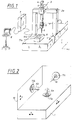
- the coordinate measuring machine of the portal type outlined in FIG. 1 consists of the machine table (1), horizontally on it in the y direction movable portal (2), which carries the so-called cross slide (3) guided on the portal arch (2a) in the x direction, and the quill (4) guided vertically in the z direction in the cross slide (3), on which the probe head (5 ) hangs with the stylus (6).
- the control of the coordinate measuring machine is denoted by (7) and the computer by (8).
- a stack of several separately calibrated and certified standards - these are setting rings with very little shape deviation - is aligned in three different positions in the measuring range (10) of the CMM so that the common axis of these rings is along one of the three measuring axes (X, Y, Z) is aligned.
- three such rings (14, 15, 16) with different diameters (R1, R2, R3) are on a common plate with the aid of suitable clamping means (13a, b) shown here in a very simplified manner attached as deformation-free as possible.
- This structure can be fixed in the three positions shown in the measuring range (10) with the aid of positioning means, not shown.
- the rings are then scanned with a correspondingly aligned button (6a, 6b, 6c) on the probe (5) at different scanning speeds (Vsc) and the measured values obtained are stored.
- Vsc scanning speeds
- the actual shape of the calibrated standards is superimposed on the residual errors of the CMM described above.
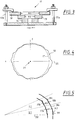
- This fact is illustrated by the diagram in FIG. 4.
- the shape deviation (17) measured with a reference device for example a special shape measuring device, is compared with the shape deviation (18) measured with the CMM at a diameter and a specific speed in a polar coordinate diagram.
- a reference device for example a special shape measuring device
- Correction values are then generated by comparing the shape deviation (18) measured with the CMM and the shape deviation (17) measured with the reference device and stored in files.
- the reference point (21) is formed by the common center point of the two compensation circles, which can be superimposed on the shape deviations (17, 18) according to the Gaussian error compensation method.
- the scanning speed, diameter (R1, R2, R3) of the rings, the position of the rings in one of the three levels (X / Y, X / Z, Y / Z) and the filter are encrypted with the Measured values have been filtered.
- the parameterization of the correction data can thus already be seen from the file names of the correction data files.
- these correction values do not have to be determined for each individual measuring point (M1, M2 .... Mn).
- the files are doubled, and the sense of rotation can then be encrypted in the file name, for example by the order of the axes when designating the plane (XY) for positive sense of rotation, (YX) for negative sense of rotation or by adding P (+) or P (-) at the end of the file name.
- the software of the KMG is set up in such a way that it informs the user of the existence of a corresponding file with correction values as soon as the selected measurement task indicates that circular, cylindrical or spherical geometric elements are to be measured, with the diameter and scanning speed in the range in question .
- the user can then decide whether to apply the correction method. If he decides to do so, the measured values that the CMM delivers are offset against the correction values (K1, K2 7), and the result is similar to that which would have been obtained when measuring on a special form measuring device.
Landscapes
- Physics & Mathematics (AREA)
- General Physics & Mathematics (AREA)
- Length Measuring Devices With Unspecified Measuring Means (AREA)
- A Measuring Device Byusing Mechanical Method (AREA)
Priority Applications (2)
| Application Number | Priority Date | Filing Date | Title |
|---|---|---|---|
| DE29624373U DE29624373U1 (de) | 1995-10-20 | 1996-10-12 | Koordinationsmeßgerät zur Koordinatenmessung an Werkstücken |
| EP02004930A EP1227300A2 (fr) | 1995-10-20 | 1996-10-12 | Machine de mesure de coordonnées pour la mesure coordonnées d'objets |
Applications Claiming Priority (2)
| Application Number | Priority Date | Filing Date | Title |
|---|---|---|---|
| DE19539148A DE19539148A1 (de) | 1995-10-20 | 1995-10-20 | Verfahren zur Koordinatenmessung von Werkstücken |
| DE19539148 | 1995-10-20 |
Related Child Applications (1)
| Application Number | Title | Priority Date | Filing Date |
|---|---|---|---|
| EP02004930A Division EP1227300A2 (fr) | 1995-10-20 | 1996-10-12 | Machine de mesure de coordonnées pour la mesure coordonnées d'objets |
Publications (3)
| Publication Number | Publication Date |
|---|---|
| EP0769677A2 true EP0769677A2 (fr) | 1997-04-23 |
| EP0769677A3 EP0769677A3 (fr) | 1998-04-22 |
| EP0769677B1 EP0769677B1 (fr) | 2002-06-12 |
Family
ID=7775388
Family Applications (2)
| Application Number | Title | Priority Date | Filing Date |
|---|---|---|---|
| EP96116380A Expired - Lifetime EP0769677B1 (fr) | 1995-10-20 | 1996-10-12 | Procédé pour la mesure de coordonnées d'objets |
| EP02004930A Withdrawn EP1227300A2 (fr) | 1995-10-20 | 1996-10-12 | Machine de mesure de coordonnées pour la mesure coordonnées d'objets |
Family Applications After (1)
| Application Number | Title | Priority Date | Filing Date |
|---|---|---|---|
| EP02004930A Withdrawn EP1227300A2 (fr) | 1995-10-20 | 1996-10-12 | Machine de mesure de coordonnées pour la mesure coordonnées d'objets |
Country Status (3)
| Country | Link |
|---|---|
| US (1) | US5895442A (fr) |
| EP (2) | EP0769677B1 (fr) |
| DE (3) | DE19539148A1 (fr) |
Cited By (6)
| Publication number | Priority date | Publication date | Assignee | Title |
|---|---|---|---|---|
| WO1999059038A1 (fr) * | 1998-05-13 | 1999-11-18 | Carl Zeiss | Appareil de mesure de coordonnees et procede pour en assurer la commande |
| US7079969B2 (en) | 2002-03-06 | 2006-07-18 | Renishaw Plc | Dynamic artefact comparison |
| DE19809589B4 (de) * | 1998-03-06 | 2009-04-02 | Carl Zeiss Industrielle Messtechnik Gmbh | Verfahren zur Kalibrierung eines Tasters eines Koordinatenmeßgerätes |
| EP2559965A1 (fr) * | 2003-09-22 | 2013-02-20 | Renishaw plc | Procédé de compensation d'erreurs dans une machine de mesure de coordonnées |
| CN113400094A (zh) * | 2021-06-07 | 2021-09-17 | 乔锋智能装备股份有限公司 | 一种用cnc加工中心机床加工件的综合检测件 |
| CN113804142A (zh) * | 2021-09-18 | 2021-12-17 | 深圳市汇泽激光科技有限公司 | 测距定位方法、测距定位装置以及测距定位设备 |
Families Citing this family (17)
| Publication number | Priority date | Publication date | Assignee | Title |
|---|---|---|---|---|
| DE19861469B4 (de) * | 1998-03-06 | 2012-12-27 | Carl Zeiss Industrielle Messtechnik Gmbh | Verfahren zur Kalibrierung eines Tasters eines Koordinatenmessgerätes |
| WO2001091438A1 (fr) * | 2000-05-19 | 2001-11-29 | Synapse Wireless, Inc. | Procede et appareil pour la creation de representations graphiques dynamiques et de notifications en temps reel sur l'etat d'un systeme gere a distance |
| GB0106245D0 (en) * | 2001-03-14 | 2001-05-02 | Renishaw Plc | Calibration of an analogue probe |
| DE10250814B4 (de) * | 2002-10-23 | 2013-04-11 | Carl Zeiss Industrielle Messtechnik Gmbh | Verfahren zum Vermessen von Werkstücken |
| JP5189806B2 (ja) * | 2006-09-07 | 2013-04-24 | 株式会社ミツトヨ | 表面形状測定装置 |
| EP1983297B1 (fr) * | 2007-04-18 | 2010-04-07 | Hexagon Metrology AB | Sonde de lecture à vitesse de balayage constante |
| FR2921476B1 (fr) * | 2007-09-24 | 2009-12-18 | Peugeot Citroen Automobiles Sa | Etalon pour machine a mesurer tridimensionnelle et procede d'utilisation d'un etalon |
| GB201003363D0 (en) | 2010-03-01 | 2010-04-14 | Renishaw Plc | Measurement method and apparatus |
| GB201113715D0 (en) | 2011-08-09 | 2011-09-21 | Renishaw Plc | Method and apparatus for inspecting workpieces |
| GB201308467D0 (en) | 2013-05-10 | 2013-06-19 | Renishaw Plc | Method and Apparatus for Inspecting Workpieces |
| CN106796095B (zh) | 2014-09-02 | 2021-05-28 | 瑞尼斯豪公司 | 操作坐标测量设备的方法、坐标测量设备和计算机程序 |
| DE102016206986B4 (de) * | 2016-04-25 | 2020-10-29 | Carl Zeiss Industrielle Messtechnik Gmbh | Verfahren und Vorrichtung zur Bestimmung einer Rundheit-Formmessabweichung sowie Lehrring |
| JP6932585B2 (ja) * | 2017-09-08 | 2021-09-08 | 株式会社ミツトヨ | 形状測定装置の制御方法 |
| JP7002892B2 (ja) * | 2017-09-08 | 2022-01-20 | 株式会社ミツトヨ | 形状測定装置の制御方法 |
| DE102019215917B4 (de) * | 2019-10-16 | 2023-05-04 | Carl Zeiss Industrielle Messtechnik Gmbh | Prüfvorrichtung, System und Verfahren zur Prüfung |
| EP3933339B1 (fr) | 2020-06-30 | 2024-03-20 | Mitutoyo Corporation | Procédé et produit programme informatique pour le filtrage d'un ensemble de données de mesure utilisable pour spécifier et/ou vérifier une caractéristique interne d'une pièce à usiner |
| DE102021105293A1 (de) | 2021-03-04 | 2022-09-08 | Carl Zeiss Industrielle Messtechnik Gmbh | Koordinatenmessgerät und Verfahren zum Kalibrieren eines Koordinatenmessgeräts |
Family Cites Families (7)
| Publication number | Priority date | Publication date | Assignee | Title |
|---|---|---|---|---|
| GB2045437B (en) * | 1979-03-30 | 1984-02-08 | Renishaw Electrical Ltd | Coordinate measuring machine |
| US4819195A (en) * | 1987-01-20 | 1989-04-04 | The Warner & Swasey Company | Method for calibrating a coordinate measuring machine and the like and system therefor |
| US4796195A (en) * | 1987-05-13 | 1989-01-03 | Cincinnati Milacron Inc. | Method for machining with improved accuracy |
| GB8713715D0 (en) * | 1987-06-11 | 1987-07-15 | Renishaw Plc | Workpiece inspection method |
| DE4245012B4 (de) * | 1992-04-14 | 2004-09-23 | Carl Zeiss | Verfahren zur Messung von Formelementen auf einem Koordinatenmeßgerät |
| DE4326551C2 (de) * | 1993-08-07 | 1997-04-17 | Heidenhain Gmbh Dr Johannes | Kalibrier-Verfahren zum Ermitteln und Kompensieren unterschiedlicher Antastkraft-Verhältnisse bei Mehrkoordinaten-Tastsystemen |
| DE4436507A1 (de) * | 1994-10-13 | 1996-04-18 | Zeiss Carl Fa | Verfahren zur Koordinatenmessung an Werkstücken |
-
1995
- 1995-10-20 DE DE19539148A patent/DE19539148A1/de not_active Ceased
-
1996
- 1996-10-12 DE DE59609327T patent/DE59609327D1/de not_active Expired - Lifetime
- 1996-10-12 EP EP96116380A patent/EP0769677B1/fr not_active Expired - Lifetime
- 1996-10-12 DE DE29624373U patent/DE29624373U1/de not_active Expired - Lifetime
- 1996-10-12 EP EP02004930A patent/EP1227300A2/fr not_active Withdrawn
- 1996-10-18 US US08/731,739 patent/US5895442A/en not_active Expired - Lifetime
Cited By (8)
| Publication number | Priority date | Publication date | Assignee | Title |
|---|---|---|---|---|
| DE19809589B4 (de) * | 1998-03-06 | 2009-04-02 | Carl Zeiss Industrielle Messtechnik Gmbh | Verfahren zur Kalibrierung eines Tasters eines Koordinatenmeßgerätes |
| WO1999059038A1 (fr) * | 1998-05-13 | 1999-11-18 | Carl Zeiss | Appareil de mesure de coordonnees et procede pour en assurer la commande |
| US6587810B1 (en) | 1998-05-13 | 2003-07-01 | Carl-Zeiss-Stiftung | Coordinate measurement device and method for controlling same |
| US7079969B2 (en) | 2002-03-06 | 2006-07-18 | Renishaw Plc | Dynamic artefact comparison |
| EP2559965A1 (fr) * | 2003-09-22 | 2013-02-20 | Renishaw plc | Procédé de compensation d'erreurs dans une machine de mesure de coordonnées |
| US8939008B2 (en) | 2003-09-22 | 2015-01-27 | Renishaw Plc | Calibration artefact for calibrating an articulating probe head |
| CN113400094A (zh) * | 2021-06-07 | 2021-09-17 | 乔锋智能装备股份有限公司 | 一种用cnc加工中心机床加工件的综合检测件 |
| CN113804142A (zh) * | 2021-09-18 | 2021-12-17 | 深圳市汇泽激光科技有限公司 | 测距定位方法、测距定位装置以及测距定位设备 |
Also Published As
| Publication number | Publication date |
|---|---|
| EP1227300A2 (fr) | 2002-07-31 |
| DE19539148A1 (de) | 1997-04-24 |
| DE59609327D1 (de) | 2002-07-18 |
| DE29624373U1 (de) | 2002-08-29 |
| EP0769677A3 (fr) | 1998-04-22 |
| US5895442A (en) | 1999-04-20 |
| EP0769677B1 (fr) | 2002-06-12 |
Similar Documents
| Publication | Publication Date | Title |
|---|---|---|
| EP0769677B1 (fr) | Procédé pour la mesure de coordonnées d'objets | |
| EP2834595B1 (fr) | Méthode et appareil pour la réduction des erreurs associées à un dispositif de rotation lors de la détermination des coordonnées d'une pièce ou lors de l'usinage d'une pièce | |
| EP3049758B1 (fr) | Réduction d'erreurs d'un dispositif de rotation qui est utilisée lors de la détermination de coordonnées d'une pièce ou lors de l'usinage d'une pièce | |
| EP1158269B1 (fr) | Procédé pour corriger des appareils de mesure de coordonnées | |
| DE69625001T2 (de) | Kalibrierung eines Gelenktastkopfs für eine Koordinaten-Positionsmaschine | |
| DE102013216093B4 (de) | Reduzieren von Fehlern einer Drehvorrichtung, insbesondere für die Bestimmung von Koordinaten eines Werkstücks oder die Bearbeitung eines Werkstücks | |
| EP0317967B1 (fr) | Dispositif permettant la déflection-rotation du palpeur de machines de mesure de coordonnées | |
| DE69619857T2 (de) | Oberflächenformvermessung | |
| EP0328750B1 (fr) | Dispositif de copiage | |
| DE69314830T2 (de) | Koordinatenmessgerät und Messverfahren | |
| DE60132073T3 (de) | Vorrichtung und verfahren zum messen der dimensions- und formabweichung von kurbelzapfen am ort des schleifens | |
| DE4436507A1 (de) | Verfahren zur Koordinatenmessung an Werkstücken | |
| DE60008512T2 (de) | System und verfahren zum nachprüfen der position eines werkzeuges einer werkzeugmaschine | |
| WO2007006448A1 (fr) | Procede de palpage d'une piece a l'aide d'un appareil de mesure de coordonnees et appareils de mesure de coordonnees associes | |
| DE68906669T2 (de) | Messsystem fuer eine werkzeugeinstellung in einer werkzeugmaschine. | |
| EP0613573B1 (fr) | Procede permettant de verifier la precision d'une machine a commande numerique | |
| DE60032635T2 (de) | Verfahren und vorrichtung zum testen von werkzeugmaschinen | |
| DE102011053117A1 (de) | Verfahren zum Kalibrieren eines Taststiftes eines Koordinatenmessgerätes sowie zur Korrektur von Messergebnissen | |
| EP0603534A1 (fr) | Dispositif et procédé pour le découpage par électro-érosion | |
| DE102020208567B4 (de) | Kalibrieren eines Referenzkörpers für die Führungsfehlerermittlung einer Maschinenachse | |
| EP3839416B1 (fr) | Dispositif de réduction d'erreurs d'un dispositif tournant lors de la détermination des valeurs mesurées des coordonnées d'une pièce | |
| DE19861469B4 (de) | Verfahren zur Kalibrierung eines Tasters eines Koordinatenmessgerätes | |
| DE19739674B4 (de) | Verfahren zur Radiuskorrektur bei Koordinatenmeßgeräten sowie Vorrichtung zur Durchführung des Verfahrens | |
| DE102005024139B4 (de) | Verfahren zur Bestimmung der Unwuchtbezugsachse und Verfahren zur Bestimmung der Unwucht sowie entsprechende Vorrichtungen | |
| DE102024108263A1 (de) | Messvorrichtung |
Legal Events
| Date | Code | Title | Description |
|---|---|---|---|
| PUAI | Public reference made under article 153(3) epc to a published international application that has entered the european phase |
Free format text: ORIGINAL CODE: 0009012 |
|
| AK | Designated contracting states |
Kind code of ref document: A2 Designated state(s): DE FR GB IT |
|
| PUAL | Search report despatched |
Free format text: ORIGINAL CODE: 0009013 |
|
| AK | Designated contracting states |
Kind code of ref document: A3 Designated state(s): DE FR GB IT |
|
| 17P | Request for examination filed |
Effective date: 19980918 |
|
| 17Q | First examination report despatched |
Effective date: 20001222 |
|
| GRAG | Despatch of communication of intention to grant |
Free format text: ORIGINAL CODE: EPIDOS AGRA |
|
| GRAG | Despatch of communication of intention to grant |
Free format text: ORIGINAL CODE: EPIDOS AGRA |
|
| GRAH | Despatch of communication of intention to grant a patent |
Free format text: ORIGINAL CODE: EPIDOS IGRA |
|
| RAP1 | Party data changed (applicant data changed or rights of an application transferred) |
Owner name: CARL-ZEISS-STIFTUNG TRADING AS CARL ZEISS Owner name: CARL ZEISS |
|
| GRAH | Despatch of communication of intention to grant a patent |
Free format text: ORIGINAL CODE: EPIDOS IGRA |
|
| GRAA | (expected) grant |
Free format text: ORIGINAL CODE: 0009210 |
|
| AK | Designated contracting states |
Kind code of ref document: B1 Designated state(s): DE FR GB IT |
|
| REG | Reference to a national code |
Ref country code: GB Ref legal event code: FG4D Free format text: NOT ENGLISH |
|
| REF | Corresponds to: |
Ref document number: 59609327 Country of ref document: DE Date of ref document: 20020718 |
|
| GBT | Gb: translation of ep patent filed (gb section 77(6)(a)/1977) |
Effective date: 20020815 |
|
| ET | Fr: translation filed | ||
| PLBI | Opposition filed |
Free format text: ORIGINAL CODE: 0009260 |
|
| PLBQ | Unpublished change to opponent data |
Free format text: ORIGINAL CODE: EPIDOS OPPO |
|
| PLBF | Reply of patent proprietor to notice(s) of opposition |
Free format text: ORIGINAL CODE: EPIDOS OBSO |
|
| 26 | Opposition filed |
Opponent name: BROWN & SHARPE GMBH Effective date: 20030228 |
|
| PLBP | Opposition withdrawn |
Free format text: ORIGINAL CODE: 0009264 |
|
| PLBF | Reply of patent proprietor to notice(s) of opposition |
Free format text: ORIGINAL CODE: EPIDOS OBSO |
|
| PLBL | Opposition procedure terminated |
Free format text: ORIGINAL CODE: EPIDOS OPPC |
|
| PLBM | Termination of opposition procedure: date of legal effect published |
Free format text: ORIGINAL CODE: 0009276 |
|
| STAA | Information on the status of an ep patent application or granted ep patent |
Free format text: STATUS: OPPOSITION PROCEDURE CLOSED |
|
| 27C | Opposition proceedings terminated |
Effective date: 20030623 |
|
| REG | Reference to a national code |
Ref country code: GB Ref legal event code: 732E |
|
| PGFP | Annual fee paid to national office [announced via postgrant information from national office to epo] |
Ref country code: FR Payment date: 20121031 Year of fee payment: 17 |
|
| REG | Reference to a national code |
Ref country code: FR Ref legal event code: ST Effective date: 20140630 |
|
| PG25 | Lapsed in a contracting state [announced via postgrant information from national office to epo] |
Ref country code: FR Free format text: LAPSE BECAUSE OF NON-PAYMENT OF DUE FEES Effective date: 20131031 |
|
| PGFP | Annual fee paid to national office [announced via postgrant information from national office to epo] |
Ref country code: GB Payment date: 20141021 Year of fee payment: 19 |
|
| PGFP | Annual fee paid to national office [announced via postgrant information from national office to epo] |
Ref country code: IT Payment date: 20141030 Year of fee payment: 19 |
|
| PGFP | Annual fee paid to national office [announced via postgrant information from national office to epo] |
Ref country code: DE Payment date: 20151022 Year of fee payment: 20 |
|
| GBPC | Gb: european patent ceased through non-payment of renewal fee |
Effective date: 20151012 |
|
| PG25 | Lapsed in a contracting state [announced via postgrant information from national office to epo] |
Ref country code: GB Free format text: LAPSE BECAUSE OF NON-PAYMENT OF DUE FEES Effective date: 20151012 Ref country code: IT Free format text: LAPSE BECAUSE OF NON-PAYMENT OF DUE FEES Effective date: 20151012 |
|
| REG | Reference to a national code |
Ref country code: DE Ref legal event code: R071 Ref document number: 59609327 Country of ref document: DE |