EP3840118A1 - Antenne à faisceaux multiples - Google Patents
Antenne à faisceaux multiples Download PDFInfo
- Publication number
- EP3840118A1 EP3840118A1 EP19275152.7A EP19275152A EP3840118A1 EP 3840118 A1 EP3840118 A1 EP 3840118A1 EP 19275152 A EP19275152 A EP 19275152A EP 3840118 A1 EP3840118 A1 EP 3840118A1
- Authority
- EP
- European Patent Office
- Prior art keywords
- dra
- array
- coverage area
- antenna
- multibeam antenna
- Prior art date
- Legal status (The legal status is an assumption and is not a legal conclusion. Google has not performed a legal analysis and makes no representation as to the accuracy of the status listed.)
- Pending
Links
Images





Classifications
-
- H—ELECTRICITY
- H01—ELECTRIC ELEMENTS
- H01Q—ANTENNAS, i.e. RADIO AERIALS
- H01Q1/00—Details of, or arrangements associated with, antennas
- H01Q1/27—Adaptation for use in or on movable bodies
- H01Q1/28—Adaptation for use in or on aircraft, missiles, satellites, or balloons
- H01Q1/288—Satellite antennas
-
- H—ELECTRICITY
- H01—ELECTRIC ELEMENTS
- H01Q—ANTENNAS, i.e. RADIO AERIALS
- H01Q15/00—Devices for reflection, refraction, diffraction or polarisation of waves radiated from an antenna, e.g. quasi-optical devices
- H01Q15/14—Reflecting surfaces; Equivalent structures
- H01Q15/16—Reflecting surfaces; Equivalent structures curved in two dimensions [2D], e.g. paraboloidal
-
- H—ELECTRICITY
- H01—ELECTRIC ELEMENTS
- H01Q—ANTENNAS, i.e. RADIO AERIALS
- H01Q19/00—Combinations of primary active antenna elements and units with secondary devices, e.g. with quasi-optical devices, for giving the antenna a desired directional characteristic
- H01Q19/10—Combinations of primary active antenna elements and units with secondary devices, e.g. with quasi-optical devices, for giving the antenna a desired directional characteristic using reflecting surfaces
- H01Q19/12—Combinations of primary active antenna elements and units with secondary devices, e.g. with quasi-optical devices, for giving the antenna a desired directional characteristic using reflecting surfaces wherein the surfaces are concave
- H01Q19/17—Combinations of primary active antenna elements and units with secondary devices, e.g. with quasi-optical devices, for giving the antenna a desired directional characteristic using reflecting surfaces wherein the surfaces are concave the primary radiating source comprising two or more radiating elements
-
- H—ELECTRICITY
- H01—ELECTRIC ELEMENTS
- H01Q—ANTENNAS, i.e. RADIO AERIALS
- H01Q21/00—Antenna arrays or systems
- H01Q21/0006—Particular feeding systems
-
- H—ELECTRICITY
- H01—ELECTRIC ELEMENTS
- H01Q—ANTENNAS, i.e. RADIO AERIALS
- H01Q21/00—Antenna arrays or systems
- H01Q21/06—Arrays of individually energised antenna units similarly polarised and spaced apart
-
- H—ELECTRICITY
- H01—ELECTRIC ELEMENTS
- H01Q—ANTENNAS, i.e. RADIO AERIALS
- H01Q21/00—Antenna arrays or systems
- H01Q21/06—Arrays of individually energised antenna units similarly polarised and spaced apart
- H01Q21/061—Two dimensional planar arrays
- H01Q21/064—Two dimensional planar arrays using horn or slot aerials
-
- H—ELECTRICITY
- H01—ELECTRIC ELEMENTS
- H01Q—ANTENNAS, i.e. RADIO AERIALS
- H01Q3/00—Arrangements for changing or varying the orientation or the shape of the directional pattern of the waves radiated from an antenna or antenna system
- H01Q3/12—Arrangements for changing or varying the orientation or the shape of the directional pattern of the waves radiated from an antenna or antenna system using mechanical relative movement between primary active elements and secondary devices of antennas or antenna systems
- H01Q3/16—Arrangements for changing or varying the orientation or the shape of the directional pattern of the waves radiated from an antenna or antenna system using mechanical relative movement between primary active elements and secondary devices of antennas or antenna systems for varying relative position of primary active element and a reflecting device
- H01Q3/20—Arrangements for changing or varying the orientation or the shape of the directional pattern of the waves radiated from an antenna or antenna system using mechanical relative movement between primary active elements and secondary devices of antennas or antenna systems for varying relative position of primary active element and a reflecting device wherein the primary active element is fixed and the reflecting device is movable
-
- H—ELECTRICITY
- H01—ELECTRIC ELEMENTS
- H01Q—ANTENNAS, i.e. RADIO AERIALS
- H01Q1/00—Details of, or arrangements associated with, antennas
- H01Q1/27—Adaptation for use in or on movable bodies
- H01Q1/28—Adaptation for use in or on aircraft, missiles, satellites, or balloons
Definitions
- the present invention relates to a multibeam antenna.
- the present invention relates to a multibeam antenna comprising a direct radiating array.
- a direct radiating array (DRA) antenna employs an array of transmit and receive elements.
- Analogue beam forming networks control the antenna elements to achieve beam steering, enabling highly flexible multibeam transmission and reception, with high gain beams.
- Space telecommunications systems continuously increase their capacity to cover the needs of multibeam antenna schemes, with narrower beam width (e.g. 0.13°) and wider scanning angles, sometimes to provide coverage to the whole Earth.
- the directivity and half power beamwidth available when using a DRA are limited by the aperture size of the array which can be accommodated in the available space of the spacecraft. For very narrow and highly directive beams, large and heavy arrays are required.
- antennas implemented with DRA technology must overcome two main problems - the accommodation of the large feed array, and grating lobe mitigation, arising due to the periodic nature of the elements of the DRA.
- Embodiments of the present invention aim to address these problems by using a parabolic reflector fed with a DRA.
- Polyomino tiling can be used, arranged in a non-periodic configuration to reduce grating lobes, while reducing the number of inputs for the digital beam forming processor.
- a multibeam antenna comprising a direct radiating array, DRA, and a reflector arranged to reflect signals radiated from the DRA in a transmission mode and to reflect signals to the DRA in a reception mode.
- the antenna is a very high throughput satellite (VHTS) antenna providing global coverage with narrow, high gain beams.
- VHTS very high throughput satellite
- the DRA may comprise a plurality of elements grouped into a plurality of polyomino-shaped subarrays.
- Each sub-array may be irregular in shape, and may have an arbitrary orientation, wherein the plurality of sub-arrays are arranged to form a rectangular shape.
- the multibeam antenna may comprise an analogue beam forming network for directing a beam coverage area within a directional coverage area, and a digital beam forming network for optimising the direction of the narrow beams within the beam coverage area.
- the multibeam antenna may further comprise mechanical steering means for repositioning the reflector.
- the multibeam antenna may comprise a feed array between the DRA and the reflector comprising a plurality of feed horns, each of which maybe activated simultaneously.
- FIG. 1 illustrates an antenna according to an embodiment of the present invention.
- the antenna comprises a DRA 2 of transmit and receive elements, and a parabolic reflector 1.
- the parabolic reflector 1 is of the form known in the art.
- the elements of the DRA 2 are of a structure to enable transmission and/or reception of signals, such as radio frequency signals, of a type (such as a power level and content) required by a particular application.
- the layout and control of the DRA elements is described in more detail below.
- the DRA 2 is positioned within the focal point of the reflector 1, with 4m of defocus. This configuration leads to a magnification factor of 4.
- the DRA 2 has 1,024 elements which are controlled in accordance with transmission and reception circuitry (not shown) to transmit and/or receive signals in dual polarization (horizontal and vertical).
- the DRA 2 interfaces with an array 3 of 1,024 corresponding conical feed horns, positioned between each element and the reflector 1, at a distance, d, of 9m.
- the feed horns have diameter 50.3mm, arranged as a rectangular lattice of 32 x 32 horns.
- the feed horns are organized to provide an interface to 64 'L'-shaped subarrays or 'tiles' of the DRA 2, in which each subarray comprises 16 transmit/receive elements.
- All of the feed horns within the feed array are activated at the same time in order to produce a certain beam of the beam layout.
- Figure 2 illustrates the tessellation of the 'L'-shaped subarrays of the feed array having a random orientation, according to an embodiment of the present invention, for an array of 1.6m x 1.6m.
- Such an array is referred to herein as a polyomino array.
- Each DRA element within a subarray is part of a group of elements which can be controlled collectively as well as individually, in a manner to be described in more detail below.
- Figure 4 illustrates an antenna coverage scheme achieved using an antenna implemented according to the configurations of Figures 1 and 2 .
- Amplitude and phase coefficients are applied to the elements of the DRA via beam forming networks, and to the subarrays, to optimize the beam in a certain direction.
- element-level control is performed by combining the DRA elements of each subarray using analogue beam forming to direct the beams that populate a 4° diameter coverage, represented by a circular area in Figure 4 .
- the 4° circle is referred to herein as a "directional coverage area" representing an area within which a set of beams may be directed.
- the directed beams themselves cover a 1° diameter circle, referred to herein as a "beam coverage area” and comprises a set of narrow beams of half-power beamwidth 0.13° and directivity 60dBi.
- Analogue beam forming is achieved using an analogue beam forming network (which may be included within the DRA housing or on a satellite payload hosting the DRA) to control the DRA elements using techniques known to those skilled in the art.
- subarray-level control is performed by computing amplitude and phase weights for each of the 64 sub-arrays using digital beam forming techniques to optimize the performance in directivity and carrier/interference (C/I) ratio for those beams within the 1° diameter circle shown in Figure 4 .
- Digital beam forming is achieved using a digital beam forming network (which may be included within the DRA housing or on a satellite payload hosting the DRA) to control the subarrays of the DRA using techniques known to those skilled in the art. Grouping the DRA elements into subarrays reduces the number of inputs to a processor of the digital beam forming network, since each input can be associated with a whole entire subarray, rather than an individual element.
- 1,024 inputs to the processor of the digital beam forming network could result in a very complex configuration.
- the elements are divided into 64 subarrays, as in the present embodiment, only 64 entries to the processor of the digital beam forming network are required.
- analogue and digital beam forming techniques renders the antenna a hybrid antenna, and leads to two degrees of freedom.
- Element-level weighting is such that each narrow beam is pointed to the centre of the 1° circle
- the subarray-level control is such that the narrow beams are re-pointed to a direction within the 1° circle which optimizes performance.
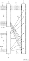
- FIG. 3 illustrates the configuration of beam forming networks according to the present embodiment.
- An analogue beam forming network 10 and a digital beam forming network 11 are shown which control the DRA 3.
- 1,024 control inputs 12-1,...,12-1024 are provided from a processor (not shown) of the analogue beam forming network 10, representing information to enable the analogue beam forming network 10 to apply phase and gain coefficients to the DRA 3 via 1,024 control outputs 13-1,...,13-1,024.
- 64 control inputs 14-1,...,14-64 are provided from a processor (not shown) of the digital beam forming network 11, representing information to enable the digital beam forming network 11 to apply phase and gain coefficients to subarrays of elements of the DRA 3 via 64 control outputs 15-1,...,15-64.
- the control outputs 15-1,...,15-64 are provided to a subarray addressing module (not shown) which co-ordinates distribution of control signals to all of the elements within the subarray.
- the reflector is mechanically steered to provide a further 4° diameter coverage area, and the element-level and subarray-level control is repeated. Mechanical steering is continued until a desired coverage area is filled, which may be the whole Earth in some embodiments.
- the principle of the build-up of coverage in this manner is shown in Figure 4 , with Figure 5(a) showing an example of how a 1° diameter beam coverage area can be populated with 121 0.13° width beams.
- Figure 5(b) shows how a 4° diameter directional coverage area could be populated with 1910 diameter circles
- Figure 5(c) shows how the Earth could be covered with different 4° diameter directional coverage areas. Elevation and azimuthal angles are shown on each of the x-axis and the y-axis respectively.
- the beams produced may be reconfigured such that their radiation pattern is optimised in terms of carrier to interference ratio (C/I) across the coverage area, and higher directivity is provided by the reflector magnification factor.
- C/I carrier to interference ratio
- an antenna according to embodiments of the present invention can be considered as a very high throughput satellite (VHTS) antenna.
- VHTS very high throughput satellite
- shape and dimensions of the reflector, the DRA, the spacing therebetween, and the arrangement of the subarrays, the width of the directional coverage area, the beam coverage area, and the width of the narrow beams can be varied in accordance with system requirements, and fully global coverage, with more than 36,000 non-simultaneous narrow, high gain beams, can be achieved.
- an antenna according to an embodiment of the invention may have a reduced number of apertures in comparison with a comparative array-fed antenna, which may require three or four reflectors to achieve the same coverage.
- An array-fed antenna is associated with degradation of the beams at the edge of the coverage area due to the distance of the feeds from the focus of the parabola.
- the separation of adjacent beams is limited due to the size of the feed horns in the array, such that there can be a problem of overlapping feeds when beams are required to be closer.
- Multiple reflectors would be used conventionally for contiguous beams, but this can be avoided in embodiments of the present invention through subarray steering by the digital beam forming network, such that only a single reflector is required.
- An antenna as described with reference to Figures 1 to 5 can be tested using tools such as GRASP from TICRA. Test results are described below, for the example of a transmission frequency of 19.7GHz, although a similar configuration could also be used for reception testing. The test results are described in connection with the beam coverage area and the directional coverage area described in Figure 4 .
- Figure 6(a) shows a beam coverage layout with no pointing in either the azimuthal or elevation directions such that the pointing direction 51 of the beam is along the boresight of a directional coverage area 50 centred on (0°, 0°), i.e. elevation angle ⁇ is zero and azimuthal angle ⁇ relative to the boresight direction.
- Figure 6(b) shows a beam coverage layout with a pointing direction ( ⁇ , ⁇ ) of (1.4°, 0°).
- the shifting of the beam coverage area in the elevation direction is represented by the rightward shift of the beam coverage area 52, while the directional coverage area 50 is unchanged.
- Figure 6(c) shows a beam coverage layout with a pointing direction ( ⁇ , ⁇ ) of (0°, 1.4°).
- the shifting of the beam coverage area in the azimuthal direction is represented by the downward shift of the beam coverage area 53, while the directional coverage area 50 is unchanged.
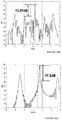
- a side-lobe level (SLL) within the field-of-view, with respect to the maximum directivity of 19.16 dB is achieved.
- Figures 7(c) and 7(d) show the same cut as illustrated in Figures 7(a) and 7(b) but with a larger element-level shift to (1.4°,0°), and with sub-array level shifting of (1.4°,0°) and (1.8°,0°) respectively.
- the element-level shifting moves the position of the beam coverage area within the directional coverage area
- the sub-array level shifting results in the optimisation of the narrow beams within the 1° circle.
- the side lobe level with respect to the maximum directivity decreases by approximately 6dB in the cases where the subarray elements and the array are pointing to different directions within the 1° coverage, in other words a 6dB reduction is seen in the test results between the radiation pattern of Figures 6(a) and 6(b) , and a 6dB reduction between the radiation pattern of Figures 6(c) and 6(d).
- Table 1 summarises the results, where ⁇ s , ⁇ s represent subarray-level elevation and azimuthal offset, and ⁇ a , ⁇ a represent element-level offsets.
- Table 1 Pointing direction test result comparison Pointing direction ⁇ ( ⁇ a , ⁇ a ) ( ⁇ s , ⁇ s ) ⁇ Maximum Directivity (dBi) SLL within the field of view (dB) ⁇ (0.0°,0.0°), (0.0°,0.0°) ⁇ 59.12 19.16 ⁇ (0.0°,0.0°), (0.4°,0.0°) ⁇ 55.78 13.27 ⁇ (1.4°,0.0°), (1.4°,0.0°) ⁇ 58.54 17.3 ⁇ (1.4°,0.0°), (1.8°,0.0°) ⁇ 55 11.61
- the grating lobes can be reduced significantly by the use of irregular elements in the DRA.
- the DRA is shown employing polyomino tiling, using 'L'-shaped elements.
- the DRA subarrays may be arranged as irregular shapes other than an 'L'-shape, such as a 'T'-shape, in which a rectangular or square array of the required size can be formed from a tessellation of arbitrary or randomly-orientated subarrays.
- Using a large parabolic reflector fed with a DRA implemented with an array of polyomino-shaped subarrays arranged with a random orientation enables a high number of highly directive beams to cover the whole Earth.
- High-capacity services are made possible with minimum signal degradation at the edge of the coverage area, with grating lobes kept out of the area of interest.
Landscapes
- Physics & Mathematics (AREA)
- Electromagnetism (AREA)
- Engineering & Computer Science (AREA)
- Astronomy & Astrophysics (AREA)
- General Physics & Mathematics (AREA)
- Remote Sensing (AREA)
- Aviation & Aerospace Engineering (AREA)
- Variable-Direction Aerials And Aerial Arrays (AREA)
- Aerials With Secondary Devices (AREA)
- Support Of Aerials (AREA)
Priority Applications (5)
| Application Number | Priority Date | Filing Date | Title |
|---|---|---|---|
| EP19275152.7A EP3840118A1 (fr) | 2019-12-19 | 2019-12-19 | Antenne à faisceaux multiples |
| CA3160748A CA3160748C (fr) | 2019-12-19 | 2020-11-30 | Antenne multifaisceau |
| AU2020406407A AU2020406407B2 (en) | 2019-12-19 | 2020-11-30 | Multibeam antenna |
| US17/782,681 US12132255B2 (en) | 2019-12-19 | 2020-11-30 | Multibeam antenna |
| PCT/EP2020/083952 WO2021121936A1 (fr) | 2019-12-19 | 2020-11-30 | Antenne multifaisceau |
Applications Claiming Priority (1)
| Application Number | Priority Date | Filing Date | Title |
|---|---|---|---|
| EP19275152.7A EP3840118A1 (fr) | 2019-12-19 | 2019-12-19 | Antenne à faisceaux multiples |
Publications (1)
| Publication Number | Publication Date |
|---|---|
| EP3840118A1 true EP3840118A1 (fr) | 2021-06-23 |
Family
ID=69411166
Family Applications (1)
| Application Number | Title | Priority Date | Filing Date |
|---|---|---|---|
| EP19275152.7A Pending EP3840118A1 (fr) | 2019-12-19 | 2019-12-19 | Antenne à faisceaux multiples |
Country Status (5)
| Country | Link |
|---|---|
| US (1) | US12132255B2 (fr) |
| EP (1) | EP3840118A1 (fr) |
| AU (1) | AU2020406407B2 (fr) |
| CA (1) | CA3160748C (fr) |
| WO (1) | WO2021121936A1 (fr) |
Cited By (1)
| Publication number | Priority date | Publication date | Assignee | Title |
|---|---|---|---|---|
| US20240006766A1 (en) * | 2021-02-24 | 2024-01-04 | Bluehalo, Llc | System and method for a digitally beamformed phased array f |
Families Citing this family (1)
| Publication number | Priority date | Publication date | Assignee | Title |
|---|---|---|---|---|
| US12609726B2 (en) * | 2022-07-13 | 2026-04-21 | Qualcomm Incorporated | Antenna side combining or antenna side selection in an L-shaped antenna module |
Citations (3)
| Publication number | Priority date | Publication date | Assignee | Title |
|---|---|---|---|---|
| US6268835B1 (en) * | 2000-01-07 | 2001-07-31 | Trw Inc. | Deployable phased array of reflectors and method of operation |
| US8077109B1 (en) * | 2007-08-09 | 2011-12-13 | University Of Massachusetts | Method and apparatus for wideband planar arrays implemented with a polyomino subarray architecture |
| US20190115975A1 (en) * | 2017-10-12 | 2019-04-18 | Rkf Engineering Solutions Llc | Hybrid analog/digital beam forming rain fade mitigation |
Family Cites Families (7)
| Publication number | Priority date | Publication date | Assignee | Title |
|---|---|---|---|---|
| US4989011A (en) * | 1987-10-23 | 1991-01-29 | Hughes Aircraft Company | Dual mode phased array antenna system |
| US6018316A (en) * | 1997-01-24 | 2000-01-25 | Ail Systems, Inc. | Multiple beam antenna system and method |
| CN113726420B (zh) * | 2015-12-31 | 2023-09-22 | 维尔塞特公司 | 使用光学馈电链路的宽带卫星通信系统 |
| RU2741489C1 (ru) * | 2017-04-10 | 2021-01-26 | Виасат, Инк. | Регулирование зоны покрытия для адаптации спутниковой связи |
| FR3073347B1 (fr) * | 2017-11-08 | 2021-03-19 | Airbus Defence & Space Sas | Charge utile de satellite comportant un reflecteur a double surface reflechissante |
| IT202000002563A1 (it) * | 2020-02-10 | 2021-08-10 | Telespazio Spa | Antenna multi-fascio a riflettore per applicazioni satellitari |
| US11411318B2 (en) * | 2020-12-08 | 2022-08-09 | Eagle Technology, Llc | Satellite antenna having pantographic trusses and associated methods |
-
2019
- 2019-12-19 EP EP19275152.7A patent/EP3840118A1/fr active Pending
-
2020
- 2020-11-30 WO PCT/EP2020/083952 patent/WO2021121936A1/fr not_active Ceased
- 2020-11-30 US US17/782,681 patent/US12132255B2/en active Active
- 2020-11-30 AU AU2020406407A patent/AU2020406407B2/en active Active
- 2020-11-30 CA CA3160748A patent/CA3160748C/fr active Active
Patent Citations (3)
| Publication number | Priority date | Publication date | Assignee | Title |
|---|---|---|---|---|
| US6268835B1 (en) * | 2000-01-07 | 2001-07-31 | Trw Inc. | Deployable phased array of reflectors and method of operation |
| US8077109B1 (en) * | 2007-08-09 | 2011-12-13 | University Of Massachusetts | Method and apparatus for wideband planar arrays implemented with a polyomino subarray architecture |
| US20190115975A1 (en) * | 2017-10-12 | 2019-04-18 | Rkf Engineering Solutions Llc | Hybrid analog/digital beam forming rain fade mitigation |
Non-Patent Citations (1)
| Title |
|---|
| XIONG ZI-YUAN ET AL: "Beamforming properties and design of the phased arrays in terms of irregular subarrays", IET MICROWAVES, ANTENNAS & PROPAGATION, THE INSTITUTION OF ENGINEERING AND TECHNOLOGY, UNITED KINGDOM, vol. 9, no. 4, 19 March 2015 (2015-03-19), pages 369 - 379, XP006051582, ISSN: 1751-8725, DOI: 10.1049/IET-MAP.2014.0308 * |
Cited By (17)
| Publication number | Priority date | Publication date | Assignee | Title |
|---|---|---|---|---|
| US20240006766A1 (en) * | 2021-02-24 | 2024-01-04 | Bluehalo, Llc | System and method for a digitally beamformed phased array f |
| US12021317B2 (en) | 2021-02-24 | 2024-06-25 | Bluehalo, Llc | System and method for a digitally beamformed phased array feed |
| US12034228B2 (en) | 2021-02-24 | 2024-07-09 | Bluehalo, Llc | System and method for a digitally beamformed phased array feed |
| US20240275048A1 (en) * | 2021-02-24 | 2024-08-15 | Bluehalo, Llc | System and method for a digitally beamformed phased array feed |
| US12080958B2 (en) * | 2021-02-24 | 2024-09-03 | Bluehalo, Llc | System and method for a digitally beamformed phased array feed |
| US12212079B2 (en) | 2021-02-24 | 2025-01-28 | Bluehalo, Llc | System and method for a digitally beamformed phased array feed |
| US12244078B2 (en) * | 2021-02-24 | 2025-03-04 | Bluehalo, Llc | System and method for a digitally beamformed phased array feed |
| US12272884B2 (en) | 2021-02-24 | 2025-04-08 | Bluehalo, Llc | System and method for a digitally beamformed phased array feed |
| US12278433B2 (en) | 2021-02-24 | 2025-04-15 | Bluehalo, Llc | System and method for a digitally beamformed phased array feed |
| US12316027B2 (en) | 2021-02-24 | 2025-05-27 | Bluehalo, Llc | System and method for a digitally beamformed phased array feed |
| US12519233B2 (en) | 2021-02-24 | 2026-01-06 | Bluehalo Llc | System and method for a digitally beamformed phased array feed |
| US12542355B2 (en) | 2021-02-24 | 2026-02-03 | Bluehalo, Llc | System and method for a digitally beamformed phased array feed |
| US12548904B2 (en) | 2021-02-24 | 2026-02-10 | Bluehalo, Llc | System and method for a digitally beamformed phased array feed |
| US12555908B2 (en) | 2021-02-24 | 2026-02-17 | Bluehalo, Llc | System and method for a digitally beamformed phased array feed |
| US12609449B2 (en) | 2021-02-24 | 2026-04-21 | Bluehalo, Llc | System and method for a digitally beamformed phased array feed |
| US12627051B2 (en) | 2021-02-24 | 2026-05-12 | Bluehalo, Llc | System and method for a digitally beamformed phased array feed |
| US12627050B2 (en) | 2021-02-24 | 2026-05-12 | Bluehalo, Llc | System and method for a digitally beamformed phased array feed |
Also Published As
| Publication number | Publication date |
|---|---|
| CA3160748A1 (fr) | 2021-06-24 |
| US12132255B2 (en) | 2024-10-29 |
| WO2021121936A1 (fr) | 2021-06-24 |
| CA3160748C (fr) | 2023-10-17 |
| AU2020406407B2 (en) | 2022-08-11 |
| AU2020406407A1 (en) | 2022-07-07 |
| US20230036249A1 (en) | 2023-02-02 |
Similar Documents
| Publication | Publication Date | Title |
|---|---|---|
| US11967775B2 (en) | Lens antenna system | |
| US11264729B2 (en) | Wide scan phased array fed reflector systems | |
| EP3242358B1 (fr) | Antenne multifaisceau à gain élevé pour communications sans fil 5g | |
| US10505609B2 (en) | Small cell beam-forming antennas | |
| CN109075454B (zh) | 用在无线通信系统中的带透镜的天线 | |
| US20110032173A1 (en) | Architectures and Methods for Novel Antenna Radiation Optimization via Feed Repositioning | |
| KR102005101B1 (ko) | 능동형 위상 배열 피드를 사용하는 폴디드 리플렉트어레이 안테나 | |
| US6268835B1 (en) | Deployable phased array of reflectors and method of operation | |
| Toso et al. | Multibeam antennas based on phased arrays: An overview on recent ESA developments | |
| US11418975B2 (en) | Base station antennas with sector splitting in the elevation plan based on frequency band | |
| CN112133999B (zh) | 基站天线 | |
| CN114843742A (zh) | 具有方位面中的全向覆盖的波束赋形天线 | |
| IL288430B1 (en) | Multi-beam on receive electronically-steerable antenna | |
| CA3160748C (fr) | Antenne multifaisceau | |
| US20190131705A1 (en) | User insensitive phased antenna array devices, systems, and methods | |
| US12206173B1 (en) | Dual mode omni / directional sectored array | |
| Kehn et al. | Characterization of dense focal plane array feeds for parabolic reflectors in achieving closely overlapping or widely separated multiple beams | |
| Elsakka et al. | A design concept of power efficient, high gain antenna system for mm-waves base stations | |
| US10777903B2 (en) | Multi-beam antenna (variants) | |
| Greda et al. | Beamforming capabilities of array-fed reflector antennas | |
| Tienda et al. | Hybrid Active Antennas for Telecom Applications | |
| RU2782177C2 (ru) | Линзовая антенная система | |
| WO2025249160A1 (fr) | Dispositif radar | |
| JPH1155031A (ja) | アレー給電反射鏡アンテナ | |
| CN117937095A (zh) | 具有混合耦合器的双波束天线 |
Legal Events
| Date | Code | Title | Description |
|---|---|---|---|
| PUAI | Public reference made under article 153(3) epc to a published international application that has entered the european phase |
Free format text: ORIGINAL CODE: 0009012 |
|
| STAA | Information on the status of an ep patent application or granted ep patent |
Free format text: STATUS: THE APPLICATION HAS BEEN PUBLISHED |
|
| AK | Designated contracting states |
Kind code of ref document: A1 Designated state(s): AL AT BE BG CH CY CZ DE DK EE ES FI FR GB GR HR HU IE IS IT LI LT LU LV MC MK MT NL NO PL PT RO RS SE SI SK SM TR |
|
| STAA | Information on the status of an ep patent application or granted ep patent |
Free format text: STATUS: REQUEST FOR EXAMINATION WAS MADE |
|
| 17P | Request for examination filed |
Effective date: 20210729 |
|
| RBV | Designated contracting states (corrected) |
Designated state(s): AL AT BE BG CH CY CZ DE DK EE ES FI FR GB GR HR HU IE IS IT LI LT LU LV MC MK MT NL NO PL PT RO RS SE SI SK SM TR |
|
| STAA | Information on the status of an ep patent application or granted ep patent |
Free format text: STATUS: EXAMINATION IS IN PROGRESS |
|
| 17Q | First examination report despatched |
Effective date: 20230124 |