EP3840551A1 - Wagenmodul - Google Patents
Wagenmodul Download PDFInfo
- Publication number
- EP3840551A1 EP3840551A1 EP19218583.3A EP19218583A EP3840551A1 EP 3840551 A1 EP3840551 A1 EP 3840551A1 EP 19218583 A EP19218583 A EP 19218583A EP 3840551 A1 EP3840551 A1 EP 3840551A1
- Authority
- EP
- European Patent Office
- Prior art keywords
- electrode
- housing
- car module
- carrier
- electronic control
- Prior art date
- Legal status (The legal status is an assumption and is not a legal conclusion. Google has not performed a legal analysis and makes no representation as to the accuracy of the status listed.)
- Withdrawn
Links
Images



Classifications
-
- H—ELECTRICITY
- H05—ELECTRIC TECHNIQUES NOT OTHERWISE PROVIDED FOR
- H05K—PRINTED CIRCUITS; CASINGS OR CONSTRUCTIONAL DETAILS OF ELECTRIC APPARATUS; MANUFACTURE OF ASSEMBLAGES OF ELECTRICAL COMPONENTS
- H05K5/00—Casings, cabinets or drawers for electric apparatus
- H05K5/02—Details
- H05K5/0208—Interlock mechanisms; Means for avoiding unauthorised use or function, e.g. tamperproof
-
- B—PERFORMING OPERATIONS; TRANSPORTING
- B60—VEHICLES IN GENERAL
- B60R—VEHICLES, VEHICLE FITTINGS, OR VEHICLE PARTS, NOT OTHERWISE PROVIDED FOR
- B60R16/00—Electric or fluid circuits specially adapted for vehicles and not otherwise provided for; Arrangement of elements of electric or fluid circuits specially adapted for vehicles and not otherwise provided for
- B60R16/02—Electric or fluid circuits specially adapted for vehicles and not otherwise provided for; Arrangement of elements of electric or fluid circuits specially adapted for vehicles and not otherwise provided for electric constitutive elements
-
- H—ELECTRICITY
- H05—ELECTRIC TECHNIQUES NOT OTHERWISE PROVIDED FOR
- H05K—PRINTED CIRCUITS; CASINGS OR CONSTRUCTIONAL DETAILS OF ELECTRIC APPARATUS; MANUFACTURE OF ASSEMBLAGES OF ELECTRICAL COMPONENTS
- H05K5/00—Casings, cabinets or drawers for electric apparatus
- H05K5/02—Details
- H05K5/0217—Mechanical details of casings
-
- H—ELECTRICITY
- H05—ELECTRIC TECHNIQUES NOT OTHERWISE PROVIDED FOR
- H05K—PRINTED CIRCUITS; CASINGS OR CONSTRUCTIONAL DETAILS OF ELECTRIC APPARATUS; MANUFACTURE OF ASSEMBLAGES OF ELECTRICAL COMPONENTS
- H05K7/00—Constructional details common to different types of electric apparatus
- H05K7/14—Mounting supporting structure in casing or on frame or rack
- H05K7/1422—Printed circuit boards receptacles, e.g. stacked structures, electronic circuit modules or box like frames
- H05K7/1427—Housings
Definitions
- the invention relates to a car module. Moreover, the invention also relates to a method for using a car module. The invention also relates to a vehicle headlight comprising a car module according to the invention.
- the invention relates to a method for using a car module according to the invention.
- Car modules that comprise electronic control units are known to control a plurality of car functionalities like controlling switching of light modules of a vehicle headlight, changing the light pattern of such light modules, or controlling functions of the engine or electrical parts of a vehicle like actuators for opening windows etc.
- these functions are not controlled by a single car module but a number of car modules which are configured to control a specific number of functions.
- car modules usually comprise a housing that encloses the electronic parts of the car module thus protecting the electronic parts from water, dust, mechanical impacts etc.
- car modules comprise housings that comprise two parts, wherein one part is fixed to another for example by way of a screwing connection. Removal of the screwing connection allows access to the electronic parts of such a car module. Such access can be desirable - for instance when replacing parts of the car module or when checking for errors or accessing data stored on the electronic parts or connecting additional electronic parts to the car module.
- a car module is also prone to manipulation. Such manipulation can be in line with requirements of the car manufacturer - for instance by changing software settings, electronic components or by adding additional components - in the event that these manipulations are performed by the car manufacturer themselves or are executed according to specific requirements of the car manufacturer and performed by legally authorized persons skilled in the art. Such manipulations are known from prior art and can be in the interest of a car manufacturer, for instance in order to access additional functionalities of a vehicle that can be activated upon additional payment.
- manipulations can also take place without the consent of the car manufacturer. Such manipulations can include illegal amendments to the performance of the power train, change of electrical settings of the vehicle, access key material stored on the car module, access PII (personally identifiable information), etc.
- vehicle driver assistance systems are quickly developing and partially already taking over driving commands. Manipulations of such car modules can bear a great safety risk for the driver of a manipulated car as well as for other traffic participants. Car modules related to such driving assistance functions and/or autonomous driving functions thus have to meet highest reliability and security requirements.
- a car module that comprises according to the invention a tamper detecting electronic control unit, wherein the electronic control unit is configured to control at least one electrically controllable function of a vehicle, for instance a light function such as low beamor high beamof a vehicle headlight, said electronic control unit comprising
- the electric relevant material can be any kind of material that allows generating a car module individual finger print that will change as a result of manipulation in a manner that an electrical parameter measured between the first and the second electrode will change as a result of the manipulation.
- Measurement of the real value can take place not only at every start-up of the electronic control unit (also referred to as ECU) but also during its operation. As such, manipulation during operation will also be detected.
- ECU electronice control unit
- opening of the housing can be reliably detected.
- Such opening is interpreted as a tampering attempt, i.e. a manipulation, and the car module can be set into a safe/ secure state, for instance allowing still operation of a car function, but in a limited range with increased safety features.
- a vehicle headlight can be put into a safe basic condition, simply emitting a low beam distribution without using higher intensity high beam functions or segment light functions which could cause glare if used incorrectly.
- the present invention allows non-destructive detection of tampering and putting the tampered car module into a safe state of operation.
- the two parts of the housing can also be permanently fixed to another by adhesive or for instance by welding. Therefore, the term "two parts" does not mean that these parts have to be configured to be separated from each other.
- the tamper detection unit can be configured to emit a verification signal in the event that the real value is within a predefineable range with regard to the reference value, wherein the electronic control unit is configured to receive the verification signal of the tamper detection unit upon start of the electronic control unit, wherein in absence of the verification signal (which also includes the presence of a failure signal) the electronic control unit is configured to initiate a failure routine.
- a failure routine could comprise deactivating the function of the ECU, sending a manipulation message to the driver screen, issuing a security warning, putting the ECU back into a safe state with limited functionality, etc.
- the at least parts of the first and second electrode are shaped in a fork-like configuration. This allows low cost manufacturing while providing sufficient manipulation sensitivity of the finger print.
- At least parts of the first and second electrode are shaped in a star-like configuration. This allows an increased manipulation sensitivity of the finger print.
- the electrodes can comprise different parts, the above-mentioned electrode configurations can also be combined based on different parts that can be connected to each other.
- the second electrode can also be arranged on the at least one carrier. This allows easier production of the electrode configuration since both electrodes can be prearranged and manufactured during production or assembling of the carrier.
- a carrier could be realized as a PCB.
- the second electrode can also be arranged on the housing, in particular by way of a component of the housing or the physical structure of the housing itself.
- manipulation of the housing, in particular attempts of bending or physically breaking parts of the housing will damage the electrode and hence have a strong impact on the finger print of the car module.
- the second electrode has to be connected in this case with the system, in particular the ECU, by way of an electric connection.
- the first and the second electrode each comprise a number of locally distributed electrode sub-groups, wherein the locally distributed electrode sub-groups of each electrode are associated and electrically connected either with the first electrode or the second electrode, wherein some electrode sub-groups are distributed on an upper side of the carrier and other electrode groups are distributed on an opposing lower side of the carrier.
- parts of the car module individual finger print can be arranged on the upper and other parts can be arranged on the lower side of the carrier.
- manipulation from each side of the carrier is detectable.
- the housing can furthermore comprise at least one protrusion extending towards a section of the carrier comprising at least a part of the first electrode, wherein electric relevant material is distributed between the protrusion and at least a part of the first electrode, physically contacting at least the protrusion. Therefore, the protrusion can basically rest on the finger print and secure a safe fit of the housing with regard to the finger print.
- Another advantage of this embodiment is that the distance between the electrodes can be reduced and the values of the relevant parameters will be higher, thus yielding an increased sensitivity.
- the electric relevant material can comprise dielectric material.
- the distribution of the dielectric material will influence the capacity measured between the first and the second electrode. As such, it will also affect the capacitive impedance between the electrodes.
- the electric relevant material can comprise adhesive.
- An adhesive is a glue for mechanically fixing an object or material.
- the adhesive can be electrically non-conductive or electrically conductive. Adding adhesive material to the electric relevant material or realizing the electric relevant material as an adhesive enables to realize a "sticky" finger print, that will partially break and deteriorate in case of manipulation.
- the electric relevant material can be at least partially electrically conductive.
- the ohmic resistance (or admittance) measured between the two electrodes can serve as an electrical relevant parameter.
- the first and second electrodes can be covered with an isolating layer.
- the first and second electrodes are directly in contact with the electrical relevant material with no separation layer in between.
- the ohmic resistance between the electrodes is sufficient low to serve as a relevant parameter P.
- the invention also relates to a vehicle headlight comprising a car module according to the invention.
- the invention relates to a method for using a car module according to the invention, wherein during the manufacture and configuration process of the car module a setup procedure is executed for determining the initial finger print and saving the corresponding reference value in the car module and in a memory that is separated from the car module. Consequently, each car module can be tracked back based on measuring its individual finger print - even back to its specific manufacturing date, place and time by way of measuring the finger print. Such a measurement is proof of manipulation since an initial finger print cannot be changed without being detected by the ECU.
- Car module individual parameters e.g. a serial number, can be related to said initial finger print. Data regarding the initial finger print could also be stored on a non-erasable memory.
- the measured real value is stored and replaces the preceding initial reference value.
- the reference value can float in line with the level of the aging effect. For instance, a change of the electric value by 10% or higher can be interpreted as a result of manipulation. However, a change of 1% could be caused by aging effects or temperature drifts. As such, a new measured value that amounts to 99% of the initial reference value can be set as a new reference value.
- a predefineable limit of a maximum allowable difference of the real value with regard to the reference value can be set, for instance 2%.
- Fig. 1a shows a schematic cross-sectional view of a car module 10 according to the invention.
- the car module 10 comprises a tamper detecting electronic control unit 1, wherein the electronic control unit 1 is configured to control at least one electrically controllable function of a vehicle, for instance a light function such as low beamor high beamof a vehicle headlight.
- the electronic control unit 1 comprises at least one carrier 2, in particular a printed circuit board, comprising an electric circuit 2a for performing the controlling by the electronic control unit 1. Moreover, the electronic control unit also comprises a housing 3 enclosing the carrier 2.
- the housing 3 comprises at least two parts 3a, 3b. A first part 3a of the housing 3 is holding the carrier 2 and a second part 3b of the housing 3 is attached to the first part 3a in order to close the housing 3 and as such enclose the carrier 2 within the housing 3.
- the electronic control unit 1 comprises a system 4 for detecting opening of the housing 3.
- this system 4 comprises a first electrode 5a arranged on the carrier 2, a second electrode 5b arranged on the carrier 2 or on the housing 3, said second electrode 5b being spaced apart from the first electrodes 5a and electric relevant material 6 that is initially distributed at least partially randomly between the first 5a and second electrode 5b.
- the distribution of said material 6 affects at least one electric parameter P measurable between the first and second electrode 5a, 5b, said initial distribution of the electric relevant material 6 being in the following referred to as car module 10 individual initial finger print FP.
- Fig. 1b shows one detail FP 1 of the finger print FP.
- the finger print FP as such is determined based on the sum of all the local finger prints, for instance FP 1 , that are connected to the same electrodes.
- distribution of a number of local finger prints and connecting into one global finger print FP allows for a higher randomization of the finger print and higher security standards since the manipulation detection is also more likely to detect partial opening of the housing 3.
- the electric relevant material 6 is mechanically connected at least to the second part 3b of the housing 3 in a manner that removal of the second part 3b of the housing 3 affects the distribution of the electric relevant material 6 between the first 5a and the second electrode 5b, thus turning the car module 10 individual initial local finger prints FP 1 to FP 4 (see Fig. 1a ), and in sum the overall finger print FP, into a manipulated finger print FP' (see Fig. 3b and 3c ).
- the system 4 further comprises a tamper detection unit 7 (for details see Fig. 6 ), that is connected to the electric circuit 2a, wherein the tamper detection unit 7 is configured to measure and store a car module 10 unique value of the electric parameter P, in particular electrical resistance, impedance, inductivity and/or capacity, measured between the first 5a and the second electrode 5b and associated with the car module 10 individual initial finger print FP.
- the measurement of the parameter P can be for instance within a range of a few kHz up to a number of MHz which will lead for instance to capacities in the range of 0.1 to 100 pF, in particular 5 to 20 pF.
- the car module 10 unique value serves as a reference value V ref , said reference value V ref representing the initial distribution of the electric relevant material 6.
- the tamper detection unit 7 is furthermore configured to measure at least at every start-up of the electronic control unit 1 the actual value of the electric parameter measured between the first 5a and the second electrode 5b, namely a real value V real .
- the tamper detection unit 7 is configured to evaluate differences between the real value V real and the reference value V ref in order to detect tampering of the housing 3 and as such tampering of the electronic control unit 1.
- the electric relevant material 6 disclosed in Fig. 1b is for instance electrically conductive adhesive 6a (for instance by mixing electrically conductive particles with non-conductive adhesive).
- this adhesive 6a is covered with an electrically non-conductive adhesive 6b that allows mechanical fixation to the upper part of the housing 3b.
- This electrical non-conductive adhesive can be made of dielectric material. As will be discussed later on, choice of the electric relevant material will affect the finger print FP and the value of the parameters related to the finger print FP.
- Fig. 2a to Fig. 2d show the arrangement of Fig. 1b with different compositions of electric relevant material 6 and different arrangement of electrodes 5a and 5b.
- Fig. 2a shows a configuration, wherein only electrically conductive adhesive 6a is applied as electrical relevant material. Both electrodes 5a and 5b are arranged on the carrier 2 and covered with an insulating layer 9.
- Fig. 2b shows a configuration that is basically similar to Fig. 1b with one exception: The electrodes 5a and 5b are not covered by an insulating layer 9 and thus directly contact the electrically conductive adhesive 6a.
- Fig. 2c shows a configuration wherein the housing 3 itself serves as second electrode 5b.
- the housing 3 has to comprise electrically conductive material and has to be in electrical contact with the system 4, in particular with the tamper detection unit 7. It is favourable when the housing is in this case not electrical connected with ground potential but has floating potential instead in order to avoid electrical influence of components which are not related to the car module itself.
- An electrically non-conductive adhesive 6b is applied between the two electrodes 5a and 5b.
- 2d shows a variant wherein the second electrode 5b is applied on the housing 3.
- the housing 3 itself can be electrically non-conductive.
- the second electrode 5b has to be connected to the tamper detection unit 7 and for this purpose comprises a connection part 5b' that extends towards the tamper detection unit 7.
- Fig. 3a to Fig. 3c show an exemplary event of manipulation of a finger print FP.
- the finger print FP of Fig. 3a is also referred to as initial finger print, i.e. the finger print that has been originally applied by the manufacturer of the car module 10.
- This finger print FP is associated with a specific value of an electric parameter P as discussed before resulting in a reference value V ref .
- Fig. 3b shows the effect of opening the housing 3, i.e. removal of the upper part 3b from the lower part 3a.
- the electrically conductive adhesive 6a that has weaker mechanical strength than the electrically non-conductive adhesive 6b, is torn into two parts, thus affecting the electrical parameter measured between the electrodes 5a and 5b.
- Fig. 4a and Fig. 4b show different electrode configurations.
- Fig. 4a shows a star-shaped configuration whereas Fig. 4b shows a fork-shaped configuration.
- Fig. 5a and Fig. 5b show exemplary at least partially randomized distributions of electric relevant material 6 on the electrodes, thus resulting in a number of local finger prints FP 1 to FP x .
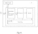
- Fig. 6 shows an exemplary layout of functional blocks of a tamper detection unit 7 for detection of opening of a housing 3.
- a tamper detection unit 7 will be connected with the electrodes 5a and 5b and measure at least one electrical parameter P, compare the values V ref and V real and determine based on this comparison if a manipulation has taken place. In the event that manipulation is detected a manipulation control routine can be triggered.
- the tamper detection unit 7 can be configured to emit a verification signal in the event that the real value V real is within a predefineable range with regard to the reference value V ref , wherein the electronic control unit 1 is configured to receive the verification signal of the tamper detection unit 7 upon start of the electronic control unit 1, wherein in absence of the verification signal the electronic control unit 1 is configured to initiate a failure routine.
- a failure routine can comprise deactivating the function of the ECU, sending a warning message to the driver screen, sending a security warning, putting the ECU back into a safe state with limited functionality, etc.
- Fig. 7 shows an exemplary view of a number of local finger prints FP 1 to FP x arranged on a car module 10.
- the housing 3 is not shown.
- these finger prints are connected with the housing 3.
- These finger prints are covering the electrodes 5a and 5b, which comprise a number of locally distributed electrode sub-groups 5a', 5a", 5b', 5b" etc., which are schematically indicated in Fig. 7 by a rectangular shaped dotted line.
- the locally distributed electrode sub-groups of each electrode are associated and electrically connected either with the first electrode 5a or the second electrode 5b.
- all the electrodes are arranged on the upper side 2' of the carrier 2, the electrodes and finger prints can also be distributed on an opposing lower side 2" of the carrier 2.
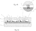
- Fig. 8a shows a schematic cross-sectional view of a car module 10, wherein the housing comprises protrusions 8 extending towards a section of the carrier 2 comprising at least a part of the first electrode 5a (see Fig. 8b ), wherein electric relevant material 6 is distributed between the protrusion 8 and at least a part of the first electrode 5a, physically contacting at least the protrusion 8.
- the invention also relates to a vehicle headlight (not shown in the figures) comprising a car module 10 according to the invention.
- the present invention also relates to a method for using a car module 10 according to the invention, wherein during the manufacture and configuration process of the car module 10 a setup procedure is executed for determining the initial finger print FP and saving the corresponding reference value in the car module 10 and in a memory that is separated from the car module 10. In the event that no tampering was detected upon start of the electronic control unit 1 the measured real value can be stored and replaces the preceding initial reference value.
Landscapes
- Engineering & Computer Science (AREA)
- Microelectronics & Electronic Packaging (AREA)
- Computer Security & Cryptography (AREA)
- Mechanical Engineering (AREA)
- Lock And Its Accessories (AREA)
- Lighting Device Outwards From Vehicle And Optical Signal (AREA)
- Vehicle Waterproofing, Decoration, And Sanitation Devices (AREA)
Priority Applications (7)
| Application Number | Priority Date | Filing Date | Title |
|---|---|---|---|
| EP19218583.3A EP3840551A1 (de) | 2019-12-20 | 2019-12-20 | Wagenmodul |
| EP20803843.0A EP4079115B1 (de) | 2019-12-20 | 2020-11-12 | Wagenmodul |
| PCT/EP2020/081858 WO2021121794A1 (en) | 2019-12-20 | 2020-11-12 | Car module |
| KR1020227014659A KR102620672B1 (ko) | 2019-12-20 | 2020-11-12 | 카 모듈 |
| CN202080088078.7A CN114868463B (zh) | 2019-12-20 | 2020-11-12 | 汽车模块 |
| US17/782,229 US12127354B2 (en) | 2019-12-20 | 2020-11-12 | Car module comprising tamper detection electronic control unit |
| JP2022537659A JP7335447B2 (ja) | 2019-12-20 | 2020-11-12 | 自動車モジュール |
Applications Claiming Priority (1)
| Application Number | Priority Date | Filing Date | Title |
|---|---|---|---|
| EP19218583.3A EP3840551A1 (de) | 2019-12-20 | 2019-12-20 | Wagenmodul |
Publications (1)
| Publication Number | Publication Date |
|---|---|
| EP3840551A1 true EP3840551A1 (de) | 2021-06-23 |
Family
ID=69411116
Family Applications (2)
| Application Number | Title | Priority Date | Filing Date |
|---|---|---|---|
| EP19218583.3A Withdrawn EP3840551A1 (de) | 2019-12-20 | 2019-12-20 | Wagenmodul |
| EP20803843.0A Active EP4079115B1 (de) | 2019-12-20 | 2020-11-12 | Wagenmodul |
Family Applications After (1)
| Application Number | Title | Priority Date | Filing Date |
|---|---|---|---|
| EP20803843.0A Active EP4079115B1 (de) | 2019-12-20 | 2020-11-12 | Wagenmodul |
Country Status (6)
| Country | Link |
|---|---|
| US (1) | US12127354B2 (de) |
| EP (2) | EP3840551A1 (de) |
| JP (1) | JP7335447B2 (de) |
| KR (1) | KR102620672B1 (de) |
| CN (1) | CN114868463B (de) |
| WO (1) | WO2021121794A1 (de) |
Families Citing this family (1)
| Publication number | Priority date | Publication date | Assignee | Title |
|---|---|---|---|---|
| DE102020214945A1 (de) * | 2020-11-27 | 2022-06-02 | Robert Bosch Gesellschaft mit beschränkter Haftung | Verfahren zum Überprüfen einer Nachricht in einem Kommunikationssystem |
Citations (4)
| Publication number | Priority date | Publication date | Assignee | Title |
|---|---|---|---|---|
| DE19512266A1 (de) * | 1994-09-23 | 1996-03-28 | Rainer Jacob | Vorrichtung zum Schutz einer elektronischen Schaltung vor Manipulation |
| EP2408286A1 (de) * | 2010-07-13 | 2012-01-18 | Thales | Vorrichtung zum Detektieren der Öffnung eines Abschlussdeckels in einer Anlage, die eine oder mehrere elektronische Leiterplatten enthält |
| WO2014170333A2 (de) * | 2013-04-19 | 2014-10-23 | Siemens Ag Österreich | Elektronisches gerät |
| US20170262661A1 (en) * | 2016-03-14 | 2017-09-14 | Mitac Computing Technology Corporation | Anti-tamper system and an anti-tamper circuit of the same |
Family Cites Families (25)
| Publication number | Priority date | Publication date | Assignee | Title |
|---|---|---|---|---|
| TW381057B (en) * | 1997-08-07 | 2000-02-01 | Hitachi Ltd | Semiconductor device |
| US6441733B1 (en) * | 2000-06-16 | 2002-08-27 | David Darrell Unterschultz | Method for making security systems more tamper resistant and a security system |
| JP4221326B2 (ja) * | 2004-04-05 | 2009-02-12 | エヌイーシーコンピュータテクノ株式会社 | データ機密保持装置及び方法 |
| US7979721B2 (en) * | 2004-11-15 | 2011-07-12 | Microsoft Corporation | Enhanced packaging for PC security |
| US7772974B2 (en) * | 2005-02-28 | 2010-08-10 | Cypak Ab | Tamper evident seal system and method |
| WO2007072251A2 (en) * | 2005-12-22 | 2007-06-28 | Koninklijke Philips Electronics N.V. | Security element and methods for manufacturing and authenticating the same |
| US7843339B2 (en) * | 2007-08-27 | 2010-11-30 | Verifone, Inc. | Secure point of sale device employing capacitive sensors |
| US8278948B2 (en) * | 2009-08-10 | 2012-10-02 | Apple Inc. | Mechanisms for detecting tampering of an electronic device |
| IT1398204B1 (it) * | 2010-02-16 | 2013-02-14 | St Microelectronics Srl | Sistema e metodo per eseguire il test elettrico di vie passanti nel silicio (tsv - through silicon vias). |
| JP5741821B2 (ja) * | 2011-03-24 | 2015-07-01 | コニカミノルタ株式会社 | データ加工送信装置およびデータ加工送信プログラム、方法 |
| WO2014027905A1 (en) * | 2012-08-15 | 2014-02-20 | Direct Payment Solutions Limited | Improvements in, or relating to, tamper evident systems |
| US10008084B2 (en) * | 2013-11-01 | 2018-06-26 | James P Tolle | Wearable, non-visible identification device for friendly force identification and intruder detection |
| US9460612B2 (en) * | 2014-05-01 | 2016-10-04 | Techip International Limited | Tamper-alert and tamper-resistant band |
| JP2016025616A (ja) * | 2014-07-24 | 2016-02-08 | レノボ・シンガポール・プライベート・リミテッド | ディスク・ドライブが記憶するデータを保護する方法および携帯式コンピュータ |
| JP6381381B2 (ja) * | 2014-09-12 | 2018-08-29 | キヤノン株式会社 | 電子機器 |
| EP3250467A4 (de) * | 2015-01-30 | 2018-07-25 | Nokia Solutions and Networks Oy | Verfahren und vorrichtung zur manipulationsdetektion |
| DE102015005556A1 (de) * | 2015-04-29 | 2016-11-03 | Giesecke & Devrient Gmbh | Siegel und Verfahren zum Prüfen eines Guts auf Manipulation |
| JP2016212683A (ja) * | 2015-05-11 | 2016-12-15 | 株式会社オートネットワーク技術研究所 | 回路基板の収容構造及び制御装置 |
| AT518344B1 (de) * | 2016-03-03 | 2019-02-15 | Zkw Group Gmbh | Bauteilgehäuse eines Fahrzeugscheinwerfers |
| DE102016203921A1 (de) * | 2016-03-10 | 2017-09-14 | Voith Patent Gmbh | Auslöseüberwachungseinrichtung für ein Verformungsrohr in einer Kupplung; Verformungsrohr für eine Kupplung und Zugkupplung |
| US9904811B2 (en) * | 2016-04-27 | 2018-02-27 | International Business Machines Corporation | Tamper-proof electronic packages with two-phase dielectric fluid |
| EP3249634B1 (de) * | 2016-05-26 | 2024-05-15 | Nxp B.V. | Manipulationsdetektionsvorrichtung |
| JP6888443B2 (ja) * | 2017-07-07 | 2021-06-16 | 富士通株式会社 | 電子装置、情報処理装置及び電子装置の制御方法 |
| EP3682471B1 (de) * | 2017-09-15 | 2023-11-08 | Cryptography Research, Inc. | Packaging-techniken für rückseitige mesh-konnektivität |
| US11244775B2 (en) * | 2018-12-11 | 2022-02-08 | Universities Space Research Association | Physically unclonable all-printed carbon nanotube network |
-
2019
- 2019-12-20 EP EP19218583.3A patent/EP3840551A1/de not_active Withdrawn
-
2020
- 2020-11-12 EP EP20803843.0A patent/EP4079115B1/de active Active
- 2020-11-12 US US17/782,229 patent/US12127354B2/en active Active
- 2020-11-12 JP JP2022537659A patent/JP7335447B2/ja active Active
- 2020-11-12 CN CN202080088078.7A patent/CN114868463B/zh active Active
- 2020-11-12 WO PCT/EP2020/081858 patent/WO2021121794A1/en not_active Ceased
- 2020-11-12 KR KR1020227014659A patent/KR102620672B1/ko active Active
Patent Citations (4)
| Publication number | Priority date | Publication date | Assignee | Title |
|---|---|---|---|---|
| DE19512266A1 (de) * | 1994-09-23 | 1996-03-28 | Rainer Jacob | Vorrichtung zum Schutz einer elektronischen Schaltung vor Manipulation |
| EP2408286A1 (de) * | 2010-07-13 | 2012-01-18 | Thales | Vorrichtung zum Detektieren der Öffnung eines Abschlussdeckels in einer Anlage, die eine oder mehrere elektronische Leiterplatten enthält |
| WO2014170333A2 (de) * | 2013-04-19 | 2014-10-23 | Siemens Ag Österreich | Elektronisches gerät |
| US20170262661A1 (en) * | 2016-03-14 | 2017-09-14 | Mitac Computing Technology Corporation | Anti-tamper system and an anti-tamper circuit of the same |
Also Published As
| Publication number | Publication date |
|---|---|
| CN114868463B (zh) | 2024-03-15 |
| CN114868463A (zh) | 2022-08-05 |
| WO2021121794A1 (en) | 2021-06-24 |
| JP7335447B2 (ja) | 2023-08-29 |
| JP2023507457A (ja) | 2023-02-22 |
| US20230010743A1 (en) | 2023-01-12 |
| US12127354B2 (en) | 2024-10-22 |
| KR102620672B1 (ko) | 2024-01-04 |
| KR20220073808A (ko) | 2022-06-03 |
| EP4079115A1 (de) | 2022-10-26 |
| EP4079115B1 (de) | 2025-10-15 |
Similar Documents
| Publication | Publication Date | Title |
|---|---|---|
| CA2349145A1 (en) | Point of sale (pos) terminal security system | |
| US9224280B2 (en) | Security wrap | |
| DE102008064723B4 (de) | System zum Schutz für Schaltungsplatinen vor unbefugtem Eingriff | |
| US11061846B2 (en) | Secure crypto module including electrical shorting security layers | |
| CN110794725B (zh) | 安全车辆控制单元 | |
| US12127354B2 (en) | Car module comprising tamper detection electronic control unit | |
| WO2013088885A1 (ja) | 情報処理装置 | |
| CN208059920U (zh) | 用于利用探测场检测物理测量值的传感器以及车辆 | |
| US9647449B2 (en) | Integrated circuit arrangement, method and system for use in a safety-critical application | |
| JP6462923B1 (ja) | 情報保護装置及び電子機器 | |
| US8179682B2 (en) | Multilayer circuit board and use of a multilayer circuit board | |
| KR102152634B1 (ko) | 이온마이그레이션 검출 장치 및 방법 | |
| CN113479074B (zh) | 电池包结构、检测系统及车辆 | |
| JP3904500B2 (ja) | 盗難防止装置 | |
| US7557724B2 (en) | Device for detecting a fault current in an electronic apparatus | |
| US20230366921A1 (en) | Electronic unit and method for testing at least one state of an electronic unit | |
| US12504457B2 (en) | Circuit device for a vehicle, and method for operating a circuit device | |
| US20250133282A1 (en) | Tamper disablement system | |
| KR100501277B1 (ko) | 차량용 엔진 제어 유니트의 고장코드 소거방법 | |
| CN117242338A (zh) | 用于检测电子设备中的冷凝湿度和/或杂质的系统和方法 | |
| BRPI1101001A2 (pt) | método de proteção mecánica e eletrÈnica de equipamentos de segurança, baseado em placas e fitas | |
| KR100514189B1 (ko) | 전자회로 시스템의 전원부 접지 상태 판단 방법 | |
| JP2000254824A (ja) | 基板実装部品及びその誤実装検知方法 | |
| BRMU9103184Y1 (pt) | disposição construtiva de proteção eletrônica e mecânica de circuitos eletrônicos sensíveis |
Legal Events
| Date | Code | Title | Description |
|---|---|---|---|
| PUAI | Public reference made under article 153(3) epc to a published international application that has entered the european phase |
Free format text: ORIGINAL CODE: 0009012 |
|
| STAA | Information on the status of an ep patent application or granted ep patent |
Free format text: STATUS: THE APPLICATION HAS BEEN PUBLISHED |
|
| AK | Designated contracting states |
Kind code of ref document: A1 Designated state(s): AL AT BE BG CH CY CZ DE DK EE ES FI FR GB GR HR HU IE IS IT LI LT LU LV MC MK MT NL NO PL PT RO RS SE SI SK SM TR |
|
| STAA | Information on the status of an ep patent application or granted ep patent |
Free format text: STATUS: THE APPLICATION IS DEEMED TO BE WITHDRAWN |
|
| 18D | Application deemed to be withdrawn |
Effective date: 20211224 |